| Skip Navigation Links | |
| Exit Print View | |

|
Sun Datacenter InfiniBand Switch 36 HTML Document Collection for Firmware Version 2.1 |
| Skip Navigation Links | |
| Exit Print View | |

|
Sun Datacenter InfiniBand Switch 36 HTML Document Collection for Firmware Version 2.1 |
USB Management Connector and Pins
InfiniBand QSFP Connector and Pins
Understanding InfiniBand Cabling
Preparing to Install the Switch
Suggested Tools for Installation
Antistatic Precautions for Installation
Verify Shipping Carton Contents
Assemble the Optical Fiber InfiniBand Cables
Install the Switch in the Rack
Verifying the InfiniBand Fabric
Network Management Troubleshooting Guidelines
Understanding Routing Through the Switch
Understanding Administrative Commands
Administering the I4 Switch Chip
Controlling the I4 Switch Chip
Administering the Subnet Manager
Controlling the Subnet Manager
Configuring Secure Fabric Management
Administering the InfiniBand Fabric
Monitoring the InfiniBand Fabric
Controlling the InfiniBand Fabric
Understanding Oracle ILOM on the Switch
Understanding Oracle ILOM Targets
Administering Oracle ILOM (CLI)
Accessing Oracle ILOM From the CLI
Switching Between the Oracle ILOM Shell and the Linux Shell
Monitoring Oracle ILOM Targets (CLI)
Controlling Oracle ILOM Targets (CLI)
Upgrading the Switch Firmware Through Oracle ILOM (CLI)
Administering Oracle ILOM (Web)
Access Oracle ILOM From the Web Interface
Monitoring Oracle ILOM Targets (Web)
Controlling Oracle ILOM Targets (Web)
Upgrade the Switch Firmware (Web)
Accessing the Rear Panel Diagram
Accessing Status Pane Information
Monitoring Parameters and Status
InfiniBand Connector Parameters and Status
Switch Connector Parameters and Status
I4 Switch Chip Port Parameters and Status
Administering Oracle ILOM (SNMP)
Monitoring Oracle ILOM Targets (SNMP)
Controlling Oracle ILOM Targets (SNMP)
Display the Sensor States (IPMI)
Display the Sensor Information (IPMI)
Display the System Event Log (IPMI)
Display FRU ID Information (IPMI)
Display Switch Status LED States (IPMI)
Disable the Locator LED (IPMI)
Understanding Oracle ILOM Commands
Identify Faults in the Oracle ILOM Event Log
Determining the Alarm State of a Component or System
Understanding Service Procedures
Antistatic Precautions for Service
Determine If a Power Supply Is Faulty
Inspecting the InfiniBand Cables
Determine If the Battery Is Faulty
Remove the Switch From the Rack
Understanding Hardware Commands
Linux Shells for Hardware Commands
Understanding InfiniBand Commands
Linux Shells for InfiniBand Commands
Understanding the SUN-DCS-IB-MIB MIB OIDs
Understanding the SUN-FABRIC-MIB MIB OIDs
Understanding the SUN-HW-TRAP-MIB MIB OIDs
Understanding the SUN-ILOM-CONTROL-MIB MIB OIDs
Understanding the SUN-PLATFORM-MIB MIB OIDs
In the rear panel diagram, there are 32 InfiniBand receptacles displayed, labeled 0A to 15A and 0B to 15B. Moving the mouse cursor over a connector name opens a small window that states the respective I4 switch chip port for that connector. This figure provides an example of moving the mouse cursor over the 0A for connection 0A.

When a connector is physically present in an InfiniBand receptacle, the receptacle changes from a black rectangle to a gray rectangle with three indicators.
This table describes the three indicators of the InfiniBand connection rectangle.
|
Moving the mouse cursor over an indicator that is orange or red opens a small window that states the reason for the respective state:
A left indicator is orange because the link has been autodisabled, either because of high error rate or suboptimal link speed and width.
A center indicator is orange because the link is at a speed slower than QDR, such as SDR or DDR.
A right indicator is red because there are errors (symbol, recovery, and so on) on the link.
This figure provides an example of moving the mouse cursor over the orange left indicator for connection 0A.

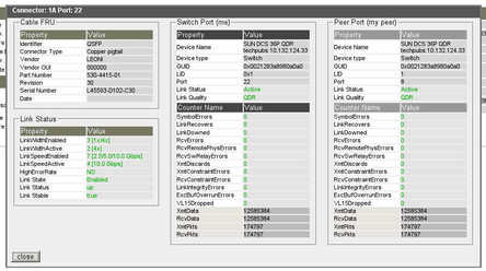
Clicking on the connection opens the InfiniBand connector status window for that connector. This figure provides an example of an InfiniBand connector status window.

At the top of the window are the connector name and the respective I4 switch chip port. There are four sets of information in the window, the cable FRU ID information, the link status, information about the I4 switch chip port (Switch Port), and similar information about the port's InfiniBand peer (Peer Port).
The cable FRU ID information includes:
Identifier
Connector type
Vendor
Vendor OUI
Part number
Revision
Serial number
Date of manufacture
The link information includes:
Link width, both enabled and active
Link speed, both enabled and active
High error rate present
Link state, status, and stability
The port information includes:
Device name and type
GUID, LID, and respective port
Link status and quality
Symbol errors
Recovery errors
Errors of various categories
Throughput statistics
Clicking Close dismisses the InfiniBand connector status window.