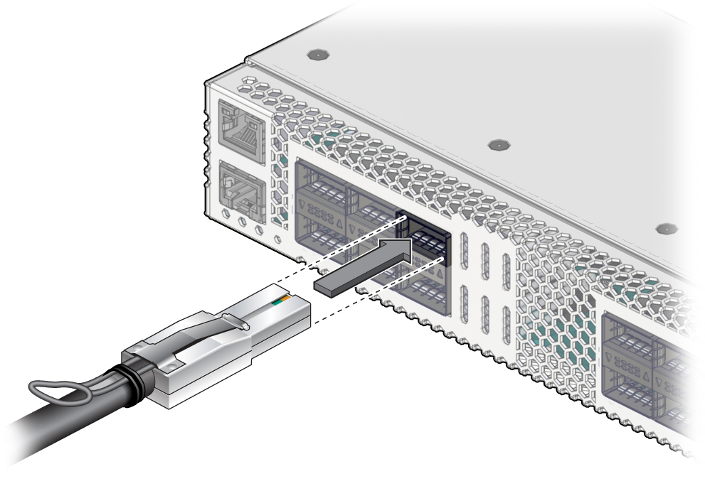
Install a Data Cable
- Remove
a data cable.
See Remove a Data Cable.
- Bring the replacement cable to the switch.
- Feed the cable through the CMA.
- Attach a cable to the switch.
- Visually inspect the
cable connector.
The shell should not be bent and should be parallel to the inner boards. If the connector is bent or damaged, use a different cable.
- Ensure that the retraction strap/lever is in the attached position.
- Determine if you are installing
a dual-part assembly or a single-part assembly.
Some optical transceiver modules are dual-part assemblies, where the module and the cable are two separate pieces, while other optical transceiver modules are single-part assemblies, where the module and the cable are a single combined unit.
- Visually inspect the
cable connector.
- Install the dual-part optical transceiver
module.
- Remove the protective end cap from the module.
- Pull the locking handle into the full horizontal position until you feel the handle click into position.
- Verify that you have the transceiver
module in the correct alignment before inserting it into the slot.
The following figure shows the correct alignment for the transceiver module.
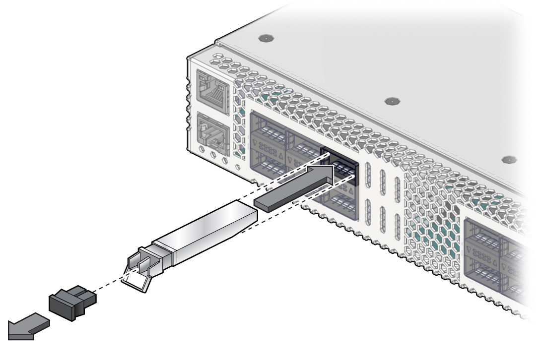
- Holding the optical transceiver module by the edges, align the optical transceiver module with the slot in the switch and slide it into the opening.
- Applying even pressure at both corners of the optical transceiver module, push the module until it is firmly seated in the slot.
- Push the handle closed to lock
the optical transceiver module in place.
Note - If you pull the locking handle down when the QSFP+ optical transceiver module is installed, you should remove the optical transceiver module entirely and reinstall it. The handle operates an internal lock. Pulling the handle down can disconnect the module, even though it might appear to be connected.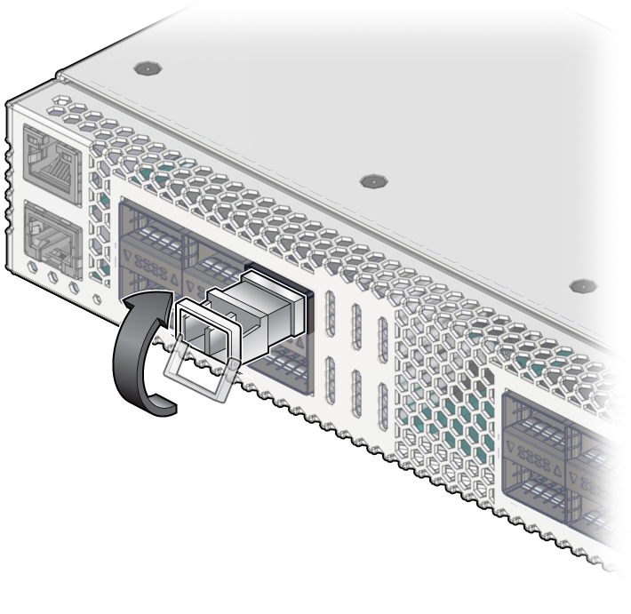
- If you are plugging in a single-part
cable assembly (transceiver and cable combined), orient the cable
connector horizontally.
Ensure that the L groove is up for the top row of receptacles, or that the L groove is down for the bottom row of receptacles.

- Plug the cable into the connector.
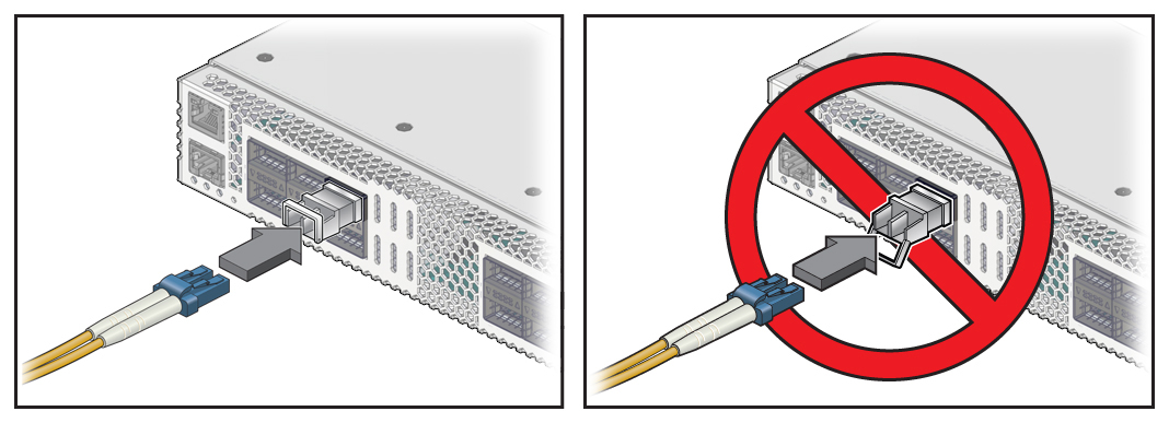
Note - The optical transceiver handle must be closed before attaching the cable to the transceiver. The handle locks the transceiver in place in the switch port.- If you are
plugging in a fiber dual-part cable assembly (transceiver and cable separate),
verify that the handle is in the locked position and connect the
cable to the optical transceiver. If the handle is in the unlocked
position, you must push it up into the locked position before attaching
the cable.
- If you are plugging in a single-part assembly, slowly slide the connector into the receptacle.
- If you are
plugging in a fiber dual-part cable assembly (transceiver and cable separate),
verify that the handle is in the locked position and connect the
cable to the optical transceiver. If the handle is in the unlocked
position, you must push it up into the locked position before attaching
the cable.
- Continue to push the connector in until you feel a detent.
- If the switch has a CMA, place
the cable into an open slot.
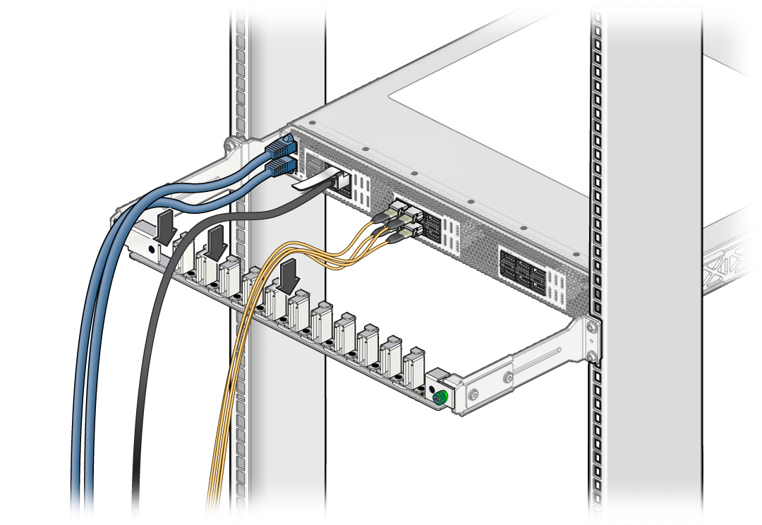
- Route the data cables so that
they do not interfere with other cables, with servicing the switch,
or with other systems.
Use hook and loop fastener straps to bundle and secure the cables.

Caution - Do not use cable zip ties to bundle or secure the cable, because the ties damage the wires inside the cable.
- Check that the Link LEDs for
cabled links are lit green.
If the Link LED is off, the link is down. If the Link LED flashes, there are errors. See Front Panel LEDs.
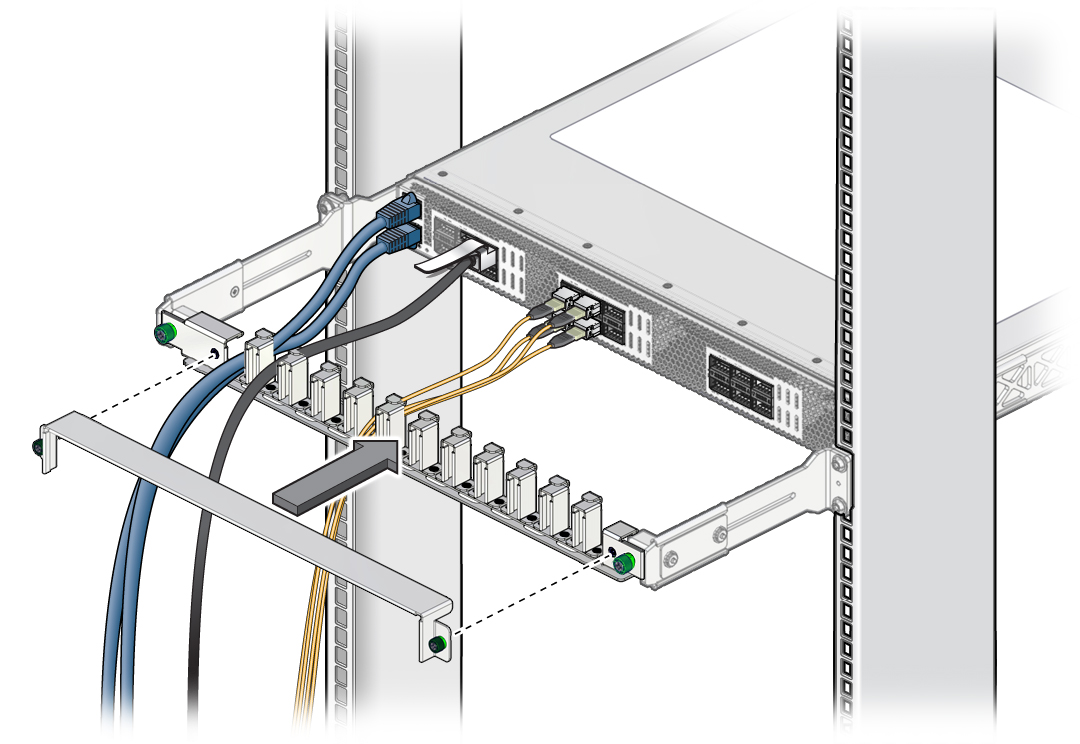
- If the switch has a CMA, replace
the CMA cover and tighten the screws.
Related Information
Switch Installation, understanding data cabling
Switch Installation, data cable guidelines
