Verify the Main Switch Kit Contents
- Identify the prerequisite and subsequent installation tasks that you must perform in conjunction with this procedure.
-
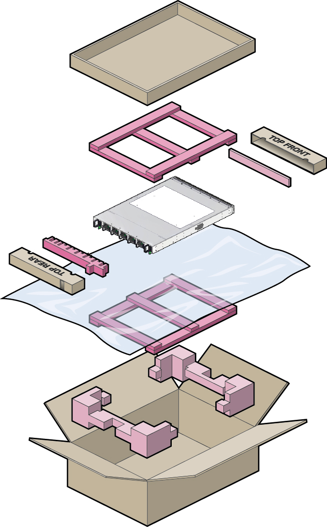
Carefully unpack the switch and the rack mount kit.
Do not discard the packing materials in the event that the switch must be returned to the factory.

-
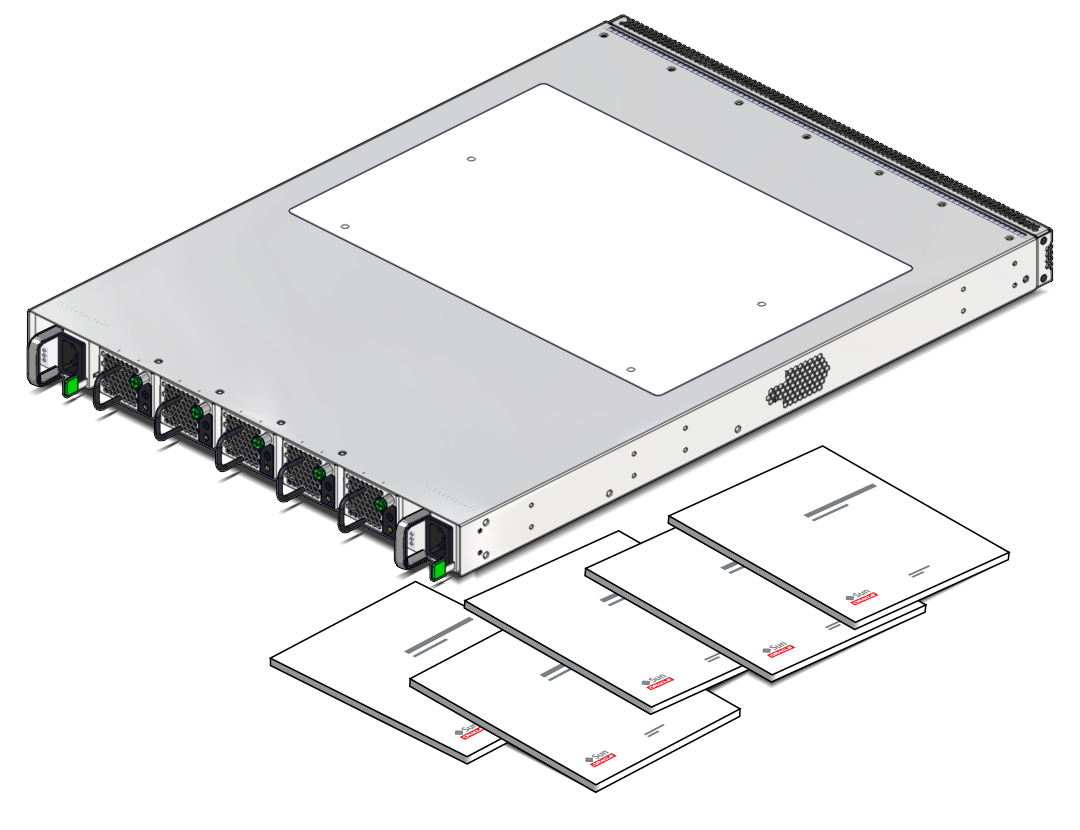
Verify that the switch kit contains one switch with power supplies and fan
modules installed.

-
Verify that the correct fan and power options are installed.
-
Check that the fan modules provide the correct direction of airflow (forward or reverse). See Environmental Specifications.
-
Check that the power supplies are the correct AC or DC type. See Electrical Specifications.
-
-
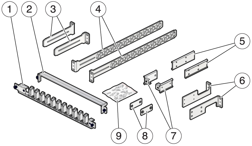
Verify that your rack rail kit is complete.
 No.Description1Cable management assembly (CMA)2CMA cover3Short rail brackets (2)4Long rail brackets (2)5Front mount brackets (2)6Rear mount brackets (2)7CMA slides (2)8Slide attachment plates (2)9Assorted screws and cage nuts:
-
M3 x 6 mm screws (16)
-
M6 x 12 mm screws (10)
-
No. 10-32 x 1/2 in screws (10)
-
No. 10-32 x 3/4 in screws (4)
-
M4 x 10 mm screws (4)
-
M6 x 16 mm (4)
-
M6 cage nuts (6)
-
-
Route the data, power, and management cables.
See Route Cables.