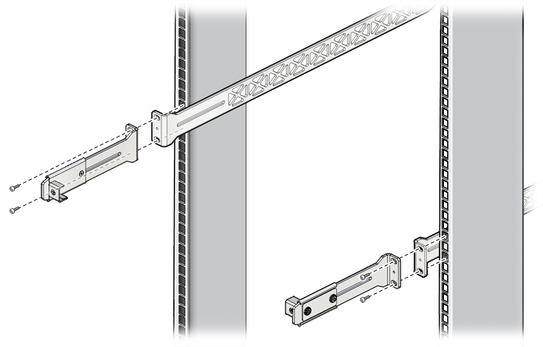
Install the Switch in the Rack
Note - The cable management assembly cannot used at the front of a cabinet if you are required to close the cabinet doors after installing the switch.
- Identify the prerequisite and subsequent installation tasks that you must perform in conjunction with this procedure.
-
Assemble the CMA brackets.
Note - Skip this step if you are installing the switch at the front of a cabinet where the doors must be kept closed.-
Place a cable management slide onto a short rail bracket.
Orient the parts so that the flanges on the slide and the bracket face in opposite directions.
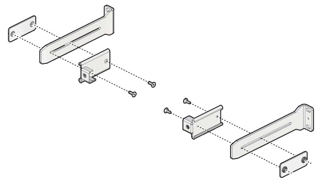
- Use a No. 2 Phillips screwdriver and two M4 x 10 mm flathead screws to attach a slide attachment plate to the CMA slide and the short rail bracket.
- Assemble the second bracket in the same way.
-
Place a cable management slide onto a short rail bracket.
-
Determine where you will attach the rack mount rails in a rack or
cabinet.
The type of fans in the switch determine whether you choose the front or the rear of the rack or cabinet as the attachment point. This choice is particularly critical if you are installing the switch in a closed cabinet.
See Power Supplies and Fans for descriptions of forward and reverse fans.
- Attach the rack mount rails to the rack.
-
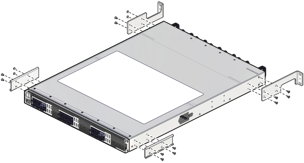
Use M3 x 6 mm screws to attach slides and brackets to the sides of the switch.
-
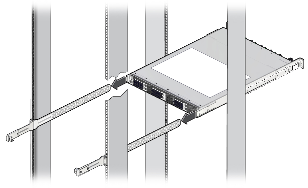
Slide the switch onto the long rail brackets.
-
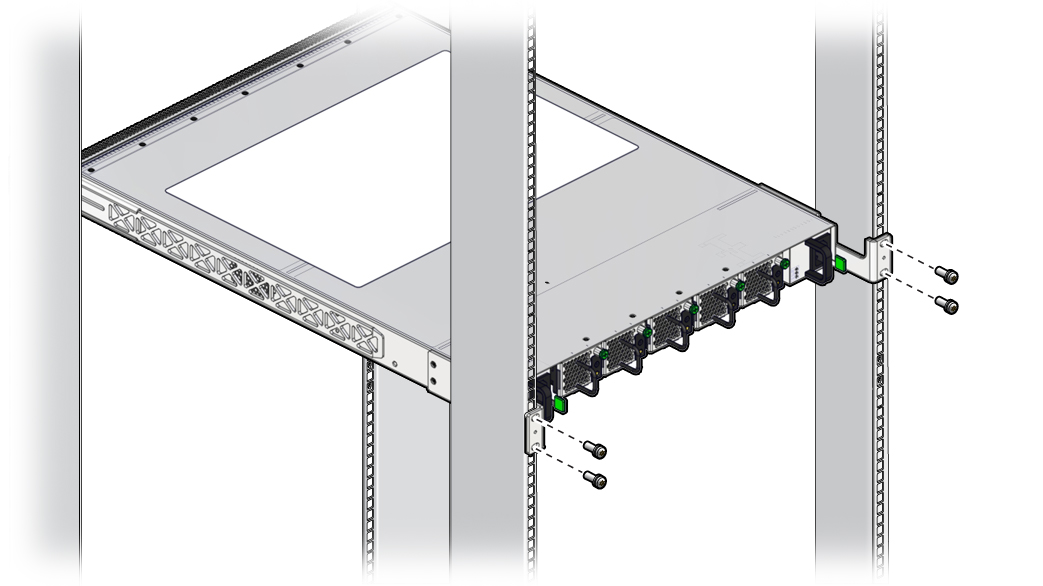
Fasten the mount brackets to the rack.
Use M6x12 mm or No. 10-32/1/2” screws as appropriate for the rack.
If the rack does not have threaded holes, install M6 cage nuts in the rack rails.
-
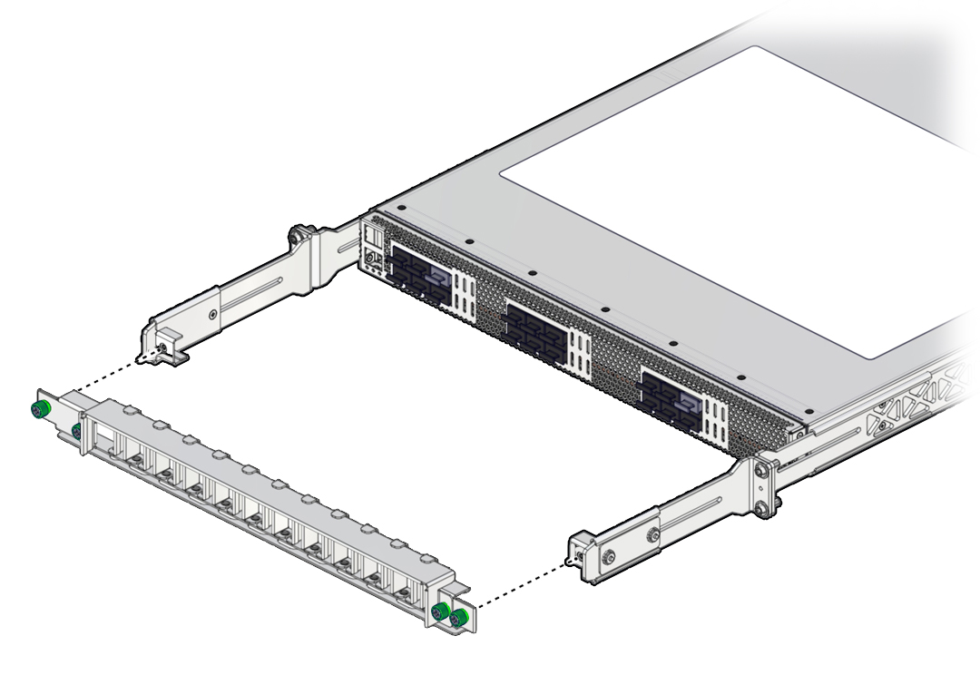
If you are using the CMA, attach the CMA bracket and CMA cover to the short
rail brackets using the outer green thumbscrews.
-
Attach the power cords.
See Attach Power Cords.
