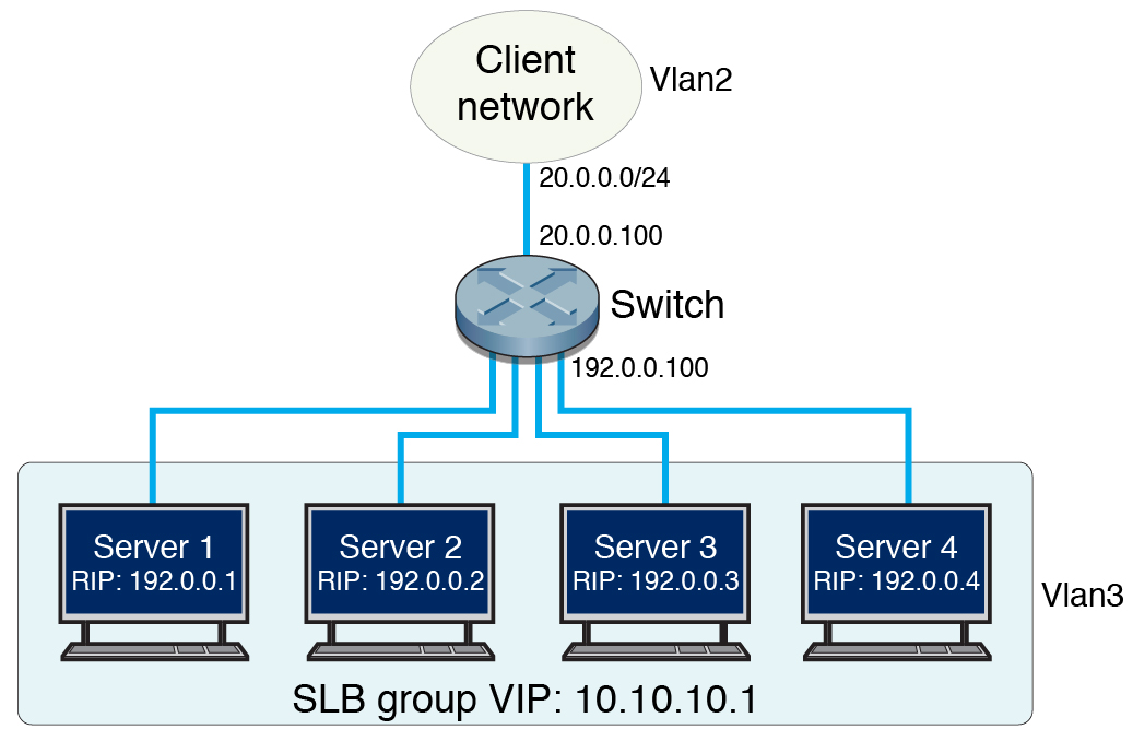
Separate VLAN
SLB Configuration
The following figure illustrates an SLB configuration with
servers and clients on separate VLANs. Servers are directly connected
to the switch.

|
|
VIP |
10.10.10.1 |
Active servers' RIP |
192.0.0.1, 192.0.0.2, 192.0.0.3 |
Standby server's RIP |
192.0.0.4 |
Client subnet, VLAN 2 |
20.0.0.0/24 |
Client subnet interface address |
20.0.0.100 |
Server subnet, VLAN 3 |
192.0.0.0/24 |
Server subnet interface address |
192.0.0.100 |
Switch ports used by servers |
extreme-ethernet 0/15-18 |
Switch ports used by client network |
extreme-ethernet 0/3-6 |
Network interface for both servers |
ixgbe0 |
|

