Basic SLB
Configuration
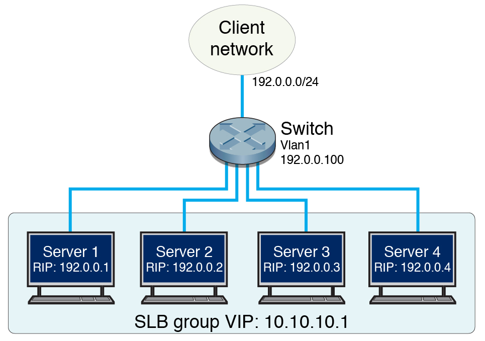
This figure illustrates the basic SLB configuration. This
configuration consists of a switch connected to a client network
and multiple servers. Clients and servers are within one single
subnet (assume that the configuration uses the switch's default VLAN, VLAN 1).
Servers are directly connected to the switch.

|
|
VIP |
10.10.10.1 |
Active servers' RIP |
192.0.0.1, 192.0.0.2, 192.0.0.3 |
Standby server's RIP |
192.0.0.4 |
Client and server subnets, VLAN 1 |
192.0.0.0/24 |
Subnet interface address |
192.0.0.100 |
Switch ports used by servers |
extreme-ethernet 0/15-18 |
Switch ports used by client network |
extreme-ethernet 0/3-6 |
Network interface for both servers |
ixgbe0 |
|
