6 Standalone PDB EPAP

This chapter describes the Standalone PDB EPAP. The information in this chapter is specific to Standalone PDB EPAP. The content in other chapters may also apply to Standalone PDB EPAP unless the content includes Real Time Database (RTDB), Service Module Cards, EAGLE connections, or Mate servers.

6.1 General Description

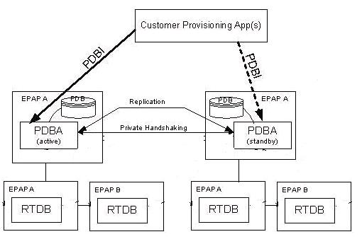
This feature allows the EPAP users to build a new EPAP server that can be configured as a 'Standalone PDB' site. This is a single EPAP A server. No EPAP B is configured with it. Only PDB database will reside on the standalone PDB site. The RTDB database is not present on the standalone PDB server and therefore, it is not connected to the Eagle. The data to the Eagle is downloaded through the multiple non-provisionable EPAP servers connected to the standalone PDB site. The active standalone PDB site is connected to the standby PDBA for the PDB replication.

Note:

The information in this chapter is specific to Standalone PDB EPAP.

Figure 6-1 EPAP Standalone PDB Architecture
img/t_epap_standlone_pdb_architecture.jpg
With this new functionality, the EPAP has the following architectures:
  1. Standalone PDB - PDB only sites
  2. Mixed EPAP - PDB and RTDB
  3. Non-Provisionable EPAP - RTDB only sites

6.1.1 Standalone PDB Provisioning Performance

This section describes the Standalone PDB configurations for the database size of 60M, 240M, and 420M with respective provisioning performances. The first and second columns of the provisioning performance tables relate to database size. The third through fifth columns relate to the example operations. The final column lists the expected Commands per Second values for the specific combinations of configuration and operations. The provisioning performance values in this section are stated in Commands per Second (CPS), and apply to only the provisioning performance of the Standalone PDB with the stated configurations. Refer to EPAP Provisioning Performance for details about provisioning performance.

Provisioning Performance for DB Size 60M

  • Example Configuration 1

    Table 6-1 shows the provisioning performance values associated with the following configuration:
    • # of RTDB Clients = 4
    • PDBI Statistics = ON
    • Self Healing Feature = OFF
    • Database Size: IMEI = 2M, Others = Full
    • PDBI Sockets = 0
    • Connection Type = Manual Import
    • Provisioning Method= 1 File (1M Command per File)

    Table 6-1 Provisioning Performance for Standalone PDB - Configuration 1

    DB SIZE: DN IMSI OPERATIONS: Operation Data Type Associated Properties CPS

    60M

    60M

    dlt

    2M DNs

    Existing DNs with SP and NE attributes

    700

    58M

    60M

    add

    2M DNs

    Add DNs with SP and NE attributes

    900

    60M

    60M

    dlt

    2M IMSIs

    Existing IMSIs with no DNs

    1000

    60M

    58M

    add

    2M IMSIs

    Add IMSIs with no DNs

    1250

  • Example Configuration 2

    Table 6-2 shows the provisioning performance values associated with the following configuration:
    • # of RTDB Clients = 4
    • PDBI Statistics = ON
    • Self Healing Feature = OFF
    • Database Size: IMEI = 2M, Others = Full
    • PDBI Sockets = 1
    • Connection Type = Normal 4 commands by TXN
    • Provisioning Method= Asynchronous

    Table 6-2 Provisioning Performance for Standalone PDB - Configuration 2

    DB SIZE: DN IMSI OPERATIONS: Operation Data Type Associated Properties CPS

    60M

    60M

    upd_sub

    2M DNs

    Existing DNs with SP and NE attributes

    250

    60M

    60M

    dlt_sub

    2M DNs

    Existing DNs with SP and NE attributes

    450

    58M

    60M

    ent_sub

    2M DNs

    Add DNs with SP and NE attributes

    450

    60M

    60M

    upd_sub

    2M IMSIs

    Existing IMSIs with no DNs

    450

    60M

    60M

    dlt_sub

    2M IMSIs

    Existing IMSIs with no DNs

    450

    60M

    58M

    ent_sub

    2M IMSIs

    Add IMSIs with no DNs

    450

  • Example Configuration 3
    Table 6-3 shows the provisioning performance values associated with the following configuration:
    • # of RTDB Clients = 4
    • PDBI Statistics = ON
    • Self Healing Feature = OFF
    • Database Size: IMEI = 2M, Others = Full
    • PDBI Sockets = 1
    • Connection Type = Single
    • Provisioning Method= Asynchronous

    Table 6-3 Provisioning Performance for Standalone PDB - Configuration 3

    DB SIZE: DN IMSI OPERATIONS: Operation Data Type Associated Properties CPS

    60M

    60M

    upd_sub

    2M DNs

    Existing DNs with SP and NE attributes

    300

    60M

    60M

    dlt_sub

    2M DNs

    Existing DNs with SP and NE attributes

    300

    58M

    60M

    ent_sub

    2M DNs

    Add DNs with SP and NE attributes

    400

    60M

    60M

    upd_sub

    2M IMSIs

    Existing IMSIs with no DNs

    300

    60M

    60M

    dlt_sub

    2M IMSIs

    Existing IMSIs with no DNs

    300

    60M

    58M

    ent_sub

    2M IMSIs

    Add IMSIs with no DNs

    400

Provisioning Performance for 240M

  • Example Configuration 4
    Table 6-4 shows the provisioning performance values associated with the following configuration:
    • # of RTDB Clients = 4
    • PDBI Statistics = ON
    • Self Healing Feature = OFF
    • Database Size: DN = 240M, IMSI = 240M, IMEI = 48M, NE=50K, ASD = 1M, DN Block=200K, IMEI Block=100K
    • DB Architecture = Compact
    • PDBI Sockets = 1
    • Connection Type = Single/Normal/File Import
    • Provisioning Method= Synchronous
    • EAGLE Connected = Yes

    Table 6-4 Provisioning Performance for Standalone PDB - Configuration 4

    DB SIZE: DN IMSI Connection Type OPERATIONS: Operation Data Type Associated Properties CPS

    240M

    240M

    Single

    ent_sub

    200K DNs

    Add DNs with SP and NE attributes

    200

    240M

    240M

    Normal

    ent_sub

    200K DNs

    Add DNs with SP and NE attributes

    450

    240M

    240M

    File Import

    ent_sub

    200K DNs

    Add DNs with SP and NE attributes

    475

    240M

    240M

    Single

    ent_sub

    200K IMSIs

    Add IMSIs with no DNs

    275

    240M

    240M

    Normal

    ent_sub

    200K IMSIs

    Add IMSIs with no DNs

    600

    240M

    240M

    File Import

    ent_sub

    200K IMSIs

    Add IMSIs with no DNs

    725

Provisioning Performance for 420M

  • Example Configuration 5
    Table 6-5 shows the provisioning performance values associated with the following configuration:
    • # of RTDB Clients = 4
    • PDBI Statistics = ON
    • Self Healing Feature = OFF
    • Database Size: DN = 420M, IMSI = 300M, IMEI = 800K, NE=50K, DN Block=800K, IMEI Block=200K
    • DB Architecture = Extreme
    • PDBI Sockets = 1
    • Connection Type = Single/Normal/File Import
    • Provisioning Method= Synchronous
    • EAGLE Connected = Yes

    Table 6-5 Provisioning Performance for Standalone PDB - Configuration 5

    DB SIZE: DN IMSI Connection Type OPERATIONS: Operation Data Type Associated Properties CPS

    420M

    300M

    Single

    ent_sub

    200K DNs

    Add DNs with SP and NE attributes

    225

    420M

    300M

    Normal

    ent_sub

    200K DNs

    Add DNs with SP and NE attributes

    450

    420M

    300M

    File Import

    ent_sub

    200K DNs

    Add DNs with SP and NE attributes

    475

    420M

    300M

    Single

    ent_sub

    200K IMSIs

    Add IMSIs with no DNs

    275

    420M

    300M

    Normal

    ent_sub

    200K IMSIs

    Add IMSIs with no DNs

    600

    420M

    300M

    File Import

    ent_sub

    200K IMSIs

    Add IMSIs with no DNs

    725

  • Example Configuration 6
    Table 6-6 shows the provisioning performance values associated with the following configuration:
    • # of RTDB Clients = 4
    • PDBI Statistics = ON
    • Self Healing Feature = OFF
    • Database Size: DN = 420M, IMSI = 300M, IMEI = 800K, NE=50K, DN Block=800K, IMEI Block=200K
    • DB Architecture = Extreme
    • PDBI Sockets = 1
    • Connection Type = Single/Normal/File Import
    • Provisioning Method= Synchronous
    • EAGLE Connected = Yes

    Table 6-6 Provisioning Performance for Standalone PDB - Configuration 6

    DB SIZE: DN IMSI Connection Type OPERATIONS: Operation Data Type Associated Properties CPS

    420M

    300M

    Single

    ent for 1 IMEI with 8 IMSIs and remaining 2 IMSIs using upd_eir command

    200K IMEIs (each associated with 10 IMSIs)

    Add DNs with SP and NE attributes

    175

    420M

    300M

    Normal

    ent for 1 IMEI with 8 IMSIs and remaining 2 IMSIs using upd_eir command

    200K IMEIs (each associated with 10 IMSIs)

    Add DNs with SP and NE attributes

    325

    420M

    300M

    File Import

    ent for 1 IMEI with 8 IMSIs and remaining 2 IMSIs using upd_eir command

    200K IMEIs (each associated with 10 IMSIs)

    Add DNs with SP and NE attributes

    275

Provisioning Performance Limitations

The provisioning performance values are stated as an indication of possible CPS based on the key factors influencing the provisioning performance. For asynchronous provisioning systems, provisioning tool behavior plays a significant role in the actual performance.

The stated provisioning performance values for Standalone PDB are not valid for Mixed EPAP configurations, where RTDB and PDB are on the same EPAP servers.

Failure to achieve possible provisioning performance values does not constitute a breach of obligations by Oracle. Oracle assumes no liability with respect to the achievable CPS; no contractual obligations with Oracle are created by these provisioning performance values.

6.2 EPAP Configuration

This feature removes the epapconfig menus and sub-menus corresponding to the RTDB, Eagle, and EPAP B (mate).

Initial epapconfig User Login

The first time the epapconfig user logs in to the system, the initial configuration is performed. A caution is displayed and the user enters 'Y' to start the configuration. The EuiDB database is built. Unlike the standard EPAP configuration, the user is not asked to configure the EPAP as provisionable or non-provisionable, as the standalone PDB site is a provisionable site.

The user will be asked to enter System Number as the standalone PDB has their dedicated System Number.

The user will be prompted to set the Network Configuration Type to either single or segmented.

In 'Single' network configuration type, all IP interfaces are supported on one Ethernet port (IP address).

In 'Segmented' network configuration type, three different interfaces are used as follows:
  • eth01 - Provisioning interface (PDBI, SOG, PDB replication, PDBA clients, Data download to RTDB)
  • eth02 - EPAP GUI Access
  • eth03 - Operations and Maintenance (O&M) interface for SSH/SFTP
  • eth04 - Backup Provisioning Interface
Caution: This is the first login of the text user interface.

Press return to continue...
Are you sure you wish to ontinue? [N]: Y
Building the intitial database on side A.
Stopping local slave
EuiDB already exists on local.
Starting local slave
Set EPAP System Number:
Enter the Network Configuration Type (1 for Single, 2 for Segmented):

Note:

The user can choose the segmented network configuration and might not configure the GUI and Operations and Maintenance network. In that case, the EPAP initial configuration may be assumed as complete and the EPAP will behave as if in single network configuration.

Main Menu

The epapconfig main menu remains unchanged for the Standalone PDB site.

Figure 6-2 EPAP Configuration Menu

/-----EPAP Configuration Menu----------\
/----------------------------------------\
|  1 | Display Configuration             |
|----|-----------------------------------|
|  2 | Configure Network Interfaces Menu |
|----|-----------------------------------|
|  3 | Set Time Zone                     |
|----|-----------------------------------|
|  4 | Exchange Secure Shell Keys        |
|----|-----------------------------------|
|  5 | Change Password                   |
|----|-----------------------------------|
|  6 | Platform Menu                     |
|----|-----------------------------------|
|  7 | Configure NTP Server              |
|----|-----------------------------------|
|  8 | PDB Configuration Menu            |
|----|-----------------------------------|
|  9 | Security                          |
|----|-----------------------------------|
| 10 | SNMP Configuration                |
|----|-----------------------------------|
| 11 | Configure Alarm Feed              |
|----|-----------------------------------|
| 12 | Configure Query Server            |
|----|-----------------------------------|
| 13 | Configure Query Server Alarm Feed |
|----|-----------------------------------|
| 14 | Configure SNMP Agent Community    |
|----|-----------------------------------|
| 15 | DB Architecture Menu              |
|----|-----------------------------------|
|  e | Exit                              |
\----------------------------------------/

Enter Choice:

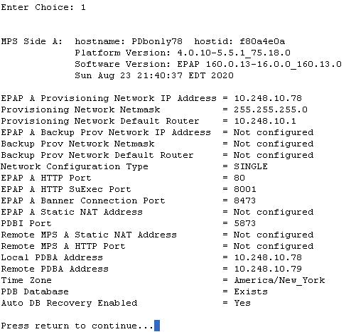
Display Configuration Menu

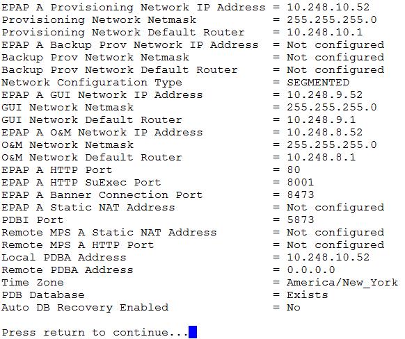
The display configuration menu option 1, displays the EPAP configuration. On standalone PDB site, only the configuration related to EPAP A and PDB are displayed, as shown in Figure 6-3.

Please note that the parameter values displayed in the below figure are just examples. The values depend on the site configuration.

Figure 6-3 Single Network Configuration Display

img/t_epap_standlone_pdb_single_network_config1.jpg

Figure 6-4 Segmented Network Configuration Display

img/t_epap_standlone_pdb_segmented_network_config1.jpg

Configure Network Interfaces Menu

The network interfaces configuration menu Option 2, does not provide the option to configure the DSM and sync interfaces because of the non-requirement of eagle and EPAP B (mate) connectivity, respectively. The menus for PDBA proxy are also be removed. The displayed menu options are dependent on the configured Network Configuration Type.

Figure 6-5 Single Network Interface Menu

img/t_epap_standlone_pdb_single_network_interface_menu.jpg

For the segmented configuration, the menu allows the user to configure all the interfaces separately. The IP version on the interfaces shall be independent of each other. This means that the user is able to configure any interface in the IPv4 only, IPv6 only or dual stack configuration.

Figure 6-6 Segmented Network Interface Menu

img/t_epap_standlone_pdb_segmented_network_interface_menu.jpg

For each menu selection, except Static NAT Addresses, the user must select whether the input is an IPv4 or IPv6 address. The Provisioning, GUI, Backup Provisioning and Operations and Maintenance Network configuration is configured the same way for a mixed EPAP.

Configure Provisioning Network Menu

The 'Configure provisioning network' menu configures the EPAP provisioning network for the standalone PDB site. Unlike the standard EPAP site, the user is not prompted for EPAP B (mate) parameters. On the standalone PDB site, the provisioning IP configured through this menu is used for the following operations: PDBI sockets, File imports for provisioning, Replication to the standby PDB and PDBA clients (RTDB).

Figure 6-7 Configure Provisioning Network

img/c_standalone_pdb_configure_provisioning_network.jpg

Configure GUI Network Menu

The Configure GUI Network menu prompts the user for the standalone PDB GUI Network IP addresses. The user is allowed to access the EPAP GUI through the configured IP only. This menu is available only on the standalone PDB sites.

Figure 6-8 Configure GUI Network

img/c_standalone_pdb_configure_gui_network.jpg

Configure Operations and Maintenance Network Menu

The Configure Operations and Maintenance Network menu prompts the user for the standalone PDB O&M Network IP addresses. The user is allowed to access the EPAP CLI through the configured IP only. This menu is available only on the standalone PDB sites. The IP configured through this menu is used for the SSH operations.

Figure 6-9 Configure Operations and Maintenance Network Menu

img/c_standalone_pdb_configure_operations_maintenance_network.jpg

Configure Backup Provisioning Network Menu

The Configure Backup Provisioning Network menu prompts the user for the standalone PDB Backup Provisioning Network IP addresses. This information allows the EPAP to communicate with the backup provisioning network. It is used when the main provisioning network (configured on eth01) goes down. The behavior is same in both single and segmented network configuration.
EPAP A backup provisioning network IP Address [0.0.0.0]:
EPAP backup provisioning network netmask [0.0.0.0]:
EPAP backup provisioning network default route [0.0.0.0]:

Note:

In case the Provisioning Network goes down and the Backup Provisioning Network is configured, all connected Non-Provisioning Networks must be reconfigured to provide the Backup Provisioning IP for the PDB from which the Non-Provisioning Network will take updates.

Configure Forwarded Ports Menu

The Configure Forwarded Ports menu provides the functionality to configure the standalone PDB ports for the Web UI on EPAP A.

Figure 6-10 Forwarded Ports Configuration Menu

img/t_epap_standlone_pdb_configure_forwarded_ports_menu.jpg

Configure Static NAT Addresses Menu

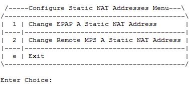
The Configure Static NAT Addresses menu provides the functionality to configure the static NAT addresses of the standalone PDB site. Each of the configured IP Address is used outside of the firewall for remote access to the MPS.

Figure 6-11 Static NAT Addresses Menu

img/t_epap_standlone_pdb_static_nat.jpg

Exchange Secure Shell Keys

The key exchange is facilitated with the remote PDBA server only.

Figure 6-12 Exchange Secure Shell Keys Menu

img/t_epap_standlone_pdb_exchange_secure_shell.jpg

Platform Menu

The platform menu shall not provide the option for RTDB Backup.

Figure 6-13 EPAP Platform Menu

img/t_epap_standlone_pdb_epap_platform.jpg

PDB Configuration Menu

The PDB Configuration menu does not provide the option to set RTDB Homing Policy, Change MPS Provisionable state and change PDBA Proxy State. The PDBA Proxy feature is not supported on the standalone PDB site as it is a single site with no EPAP B (mate).

Figure 6-14 Configure PDB Menu

/-----Configure PDB Menu-----------\
/------------------------------------\
|  1 | Configure PDB Network         |
|----|-------------------------------|
|  2 | Configure PDB Capacity        |
|----|-------------------------------|
|  3 | Create PDB                    |
|----|-------------------------------|
|  4 | Change Auto DB Recovery State |
|----|-------------------------------|
|  e | Exit                          |
\------------------------------------/

Configure PDB Network Menu

The Configure PDB Network menu prompts the user for the remote PDB IP address. Unlike the mixed EPAP, the standalone PDB site ask only for PDBA A IP address and not the PDBA B IP Address.
This MPS is configured to be provisionable.  The EPAP local PDBA
address is currently set to 10.250.51.130.
EPAP software and PDBA are running.  Stop them? [N]: Y
The EPAP local PDBA IP Address is 10.250.51.130.
EPAP remote PDBA IP Address [0.0.0.0]: 10.250.51.131
The server does not know of 10.250.51.131.
Will just exchange host keys for the name given!
Password of epapdev:
The server does not know of 10.250.51.131.
Will just exchange host keys for the name given!
ssh is working correctly.

6.3 EPAP GUI

This feature removes the EPAP GUI menus and sub-menus corresponding to the RTDB, Eagle and EPAP B (mate). On the standalone PDB site, the GUI menus are as follows.

Figure 6-15 EPAP A GUI Main Menu

img/t_epap_standlone_pdb_epap_gui_menu.jpg

Maintenance sub-menu

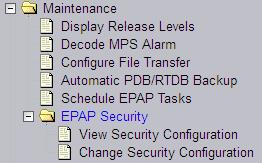
The maintenance sub-menu no longer provides the option to activate the Force standby mode and the RTDB Audit. The option to take automatic backup configures the PDB backup on the Standalone PDB site and the RTDB backup is scheduled for all connected non-provisionable pairs.

Figure 6-16 EPAP A Maintenance sub-menu
img/t_epap_standlone_pdb_maintenance_sub.jpg

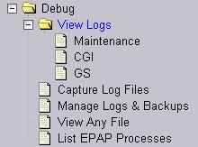
Debug sub-menu

The debug sub-menu provides the option to view only Maintenance, CGI and GS logs.

Figure 6-17 EPAP A Debug sub-menu

img/t_epap_standlone_pdb_debug.jpg

Platform sub-menu

The Platform sub-menu provides the following options:

Figure 6-18 EPAP A Platform sub-menu

img/t_epap_standlone_pdb_platform_sub.jpg

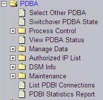
PDBA sub-menu

The PDBA sub-men remains unchanged.

Figure 6-19 EPAP A PDBA Main Menu

img/t_epap_standlone_pdb_pdba_main.jpg

User Administration sub-menu

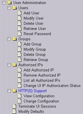
The User Administration sub-menu remains unchanged.

Figure 6-20 EPAP A User Administration Menu
img/t_epap_standlone_pdb_user_admin_menu.jpg

6.4 EPAP GUI Banner Section

The banner frame containing EPAP A server information extends the entire width of the browser window.

The EPAP A areas contain information and displays to inform the user about the status and operation of the servers.

The Oracle Communications logo icon is located at the top left of the banner applet.

Figure 6-21 EPAP A GUI Banner Section


img/c_epap_gui_banner_components_bare.jpg

In the dual stack configuration, the EPAP GUI is accessible through both configured IPv4 and IPv6 IPs. The IP must be enclosed in the square brackets. Examples are displayed in the following figures:

Figure 6-22 Banner For Mixed EPAP With Watchers and No Remote PDBA

img/c_epap_gui_banner_mixed_with_watchers_no_remote_pdba.jpg

Figure 6-23 Banner for Mixed EPAP With Remote PDBA and No Watchers

img/c_epap_gui_banner_mixed_remote_pdba_no_watchers.jpg

Figure 6-24 Banner For Mixed EPAP With IPv6 Configuration With Watchers and Remote PDBA

img/c_epap_gui_banner_mixed_epap_ipv6_with_watchers_and_remote_pdba.jpg

Figure 6-25 Banner for PDBonly EPAP With Watchers and Remote PDBA

img/c_epap_gui_banner_pdbonly_with_watchers_and_remote_pdba.jpg

6.5 Standalone PDB EPAP Configuration Procedure

Perform the configuration procedure by following these steps in the text-based user interface. After you have connected to an MPS as described in Initial Setup and Connecting to MPSs, perform this procedure to configure the EPAPs in your network.

Note:

Initial configuration cannot be performed through the GUI because the IP addresses required for browser connectivity are not defined until the initial configuration using the text-based UI is completed.

Note:

RTDB-related executables will not be allowed to run from the CLI. Different error messages may be displayed if the user tries to execute any RTDB related executable.

Using the set up and connection described previously, connect to an MPS to perform configuration. In a typical installation, connect directly to the MPS at EAGLE A to configure it, then use ssh to connect to the MPS at EAGLE B and configure it.

After connecting to the MPS on EAGLE A, you are prompted to log in.

  1. Log in as epapconfig.
    A caution notice is displayed. Evaluate the conditions listed.
    
    mpsa-f0c7c3 console login: epapconfig
    Password: 
    Caution: This is the first login of the text user interface. 
    Press return to continue…
    
  2. Press Return to continue.

    After pressing Return to continue, you can abort or proceed with the initial configuration.

    Note:

    Pressing Return accepts the default value n.
    
    Are you sure you wish to continue? [N]: y
    Building the initial database on side A.
      Stopping local slave
      EuiDB already exists.
      Starting local slave
    Set EPAP System Number:
    
  3. Enter a valid System Number and press Return .

    Enter the Network configuration Type (1 for Single, 2 for Segmented).

  4. Enter the Network Configuration Type and press Return .
    Upon successful configuration file setup, the EPAP Configuration Menu appears (for the first time) with associated header information.

    The server designation of MPS A at this site is displayed along with hostname, hostid, Platform Version, Software Version, and the date.

    
    MPS Side A:  hostname: SantosA  hostid: fa0a8233
                 Platform Version: 4.0.10-5.5.1_75.18.0
                 Software Version: EPAP 160.0.13-16.0.0_160.13.0
                 Fri Aug 15 10:24:54 EDT 2014
    
    /-------EPAP Configuration Menu--------\
    /----------------------------------------\
    |  1 | Display Configuration             |
    |----|-----------------------------------|
    |  2 | Configure Network Interfaces Menu |
    |----|-----------------------------------|
    |  3 | Set Time Zone                     |
    |----|-----------------------------------|
    |  4 | Exchange Secure Shell Keys        |
    |----|-----------------------------------|
    |  5 | Change Password                   |
    |----|-----------------------------------|
    |  6 | Platform Menu                     |
    |----|-----------------------------------|
    |  7 | Configure NTP Server              |
    |----|-----------------------------------|
    |  8 | PDB Configuration Menu            |
    |----|-----------------------------------|
    |  9 | Security                          |
    |----|-----------------------------------|
    | 10 | SNMP Configuration                |
    |----|-----------------------------------|
    | 11 | Configure Alarm Feed              |
    |----|-----------------------------------|
    | 12 | Configure Query Server            |
    |----|-----------------------------------|
    | 13 | Configure Query Server Alarm Feed |
    |----|-----------------------------------|
    | 14 | Configure SNMP Agent Community    |
    |----|-----------------------------------|
    |  e | Exit                              |
    \----------------------------------------/
    
    Enter Choice: 
    
  5. Choose option 1, Display Configuration.
    This option provides a means of verifying EPAP A Provisioning Network IP address, the Time Zone, and other provisioning values for the MPS on EAGLE A.

    Figure 6-26 Single Network Configuration Menu

    img/t_epap_standlone_pdb_single_network_config.jpg

    Figure 6-27 Segmented Network Configuration Menu

    img/t_epap_standlone_pdb_segmented_network_config.jpg
  6. Press Return to return to the EPAP Configuration Menu.
  7. Choose option 2, Configure Network Interfaces Menu.
    
    Enter Choice 2:
    
    
    MPS Side A:  hostname: PDbonly78  hostid: f80a4e0a
                 Platform Version: 4.0.10-5.5.1_75.18.0
                 Software Version: EPAP 160.0.13-16.0.0_160.13.0
                 Sun Aug 23 10:24:54 EDT 2014
    
     /-----Configure Network Interfaces Menu----\
    /--------------------------------------------\
    |  1 | Configure Provisioning Network        |
    |----|---------------------------------------|
    |  2 | Configure Backup Provisioning Network |
    |----|---------------------------------------|
    |  3 | Configure Forwarded Ports             |
    |----|---------------------------------------|
    |  4 | Configure Static NAT Addresses        |
    |----|---------------------------------------|
    |  e | Exit                                  |
    \--------------------------------------------/
    Enter Choice: 


     /-----Configure Network Interfaces Menu-----------\
    /---------------------------------------------------\
    |  1 | Configure Provisioning Network               |
    |----|----------------------------------------------|
    |  2 | Configure GUI Network                        |
    |----|----------------------------------------------|
    |  3 | Configure Operations and Maintenance Network |
    |----|----------------------------------------------|
    |  4 | Configure Backup Provisioning Network        |
    |----|----------------------------------------------|
    |  5 | Configure Forwarded Ports                    |
    |----|----------------------------------------------|
    |  6 | Configure Static NAT Addresses               |
    |----|----------------------------------------------|
    |  e | Exit                                         |
    \---------------------------------------------------/
    Enter choice: 
    
  8. Choose option 1, Configure Provisioning Network.

    The Configure Provisioning Network Menu allows you to accept the default IP address values presented by the configuration software for EPAP A provisioning network and network netmask, or enter a specific IP value previously received from the customer for the MPS.

    Note:

    127.0.0.1 is not a valid IP address for this operation. 0.0.0.0 is a valid IP address and can be used to reset the VIP/backup provisioning IP address.

    Refer to the information recorded in Table 5-1 through Table 5-4 for the correct addresses.

    Note:

    No default value is provided for the EPAP provisioning network default router. This value must be received from the customer.
    The display for the submenu for configuring communications networks appears.
    
    EPAP A provisioning network IP Address [10.248.10.49]:
    EPAP provisioning network netmast [255.255.255.0]:
    EPAP provisioning network default router [10.248.10.1]:
    
  9. Press the Return to return to the Configure Network Interfaces Menu. Choose 2, Configure GUI Network.

    The Configure GUI Network menu prompts the user for the standalone PDB GUI Network IP addresses. The user is allowed to access the EPAP GUI through the configured IP only. This menu is available only on standalone PDB sites.

    
    EPAP A GUI network IP Address [192.168.3.10]:
    EPAP GUI network netmast [255.255.255.0]:
    EPAP GUI network route [192.168.3.1]:
     
    
  10. Press Return to return to the Configure Network Interfaces Menu. Choose 3, Configure Operations and Maintenance Network.

    The Configure Operations and Maintenance Network menu prompts the user for the standalone PDB O&M Network IP addresses. The user is allowed to access the EPAP CLI through the configured IP only. This menu is available only on the standalone PDB sites. The IP configured through this menu is used for the SSH operations.

    EPAP A Operations and Maintenance network IP Address [192.168.4.10]:
    EPAP Operations and Maintenance network netmask [255.255.255.0]:
    EPAP Operations and Maintenance network route [192.168.4.1]:
  11. Press Return to return to the Configure Network Interfaces Menu. Choose 2 or 4 (depending on the Menu displayed by the Network Type Configuration), Configure Backup Provisioning Network.

    This menu selection prompts you for all information necessary to set up a second interface for the customer's Provisioning Network.

    Note:

    127.0.0.1 is not a valid IP address for this operation.

    . The address information should be received from the customer for the MPS. Refer to the information recorded in Table 5-1 through Table 5-4 for the correct addresses.

    The IP address for this interface must be on a different class C subnet than the primary Provisioning Network address. You must set up a second default router address to coincide with the Backup Provisioning Network. There are no default values for any of these fields. The customer must supply all the information. The Backup Provisioning Network cannot be configured using the platcfg utility.

    EPAP A backup provisioning network IP Address [0.0.0.0]:
    EPAP backup provisioning network netmask [0.0.0.0]:
    EPAP backup provisioning network default route [0.0.0.0]:
  12. Press Return to return to the Configure Network Interfaces Menu.

    Note:

    Unless the MPS is separated from the GUI workstations and provisioning systems by a port forwarding firewall, skip 13 through 16 and proceed to 20, Configure Forwarded Ports.
  13. Choose option 3 or 5 (depending on the Menu displayed by the Network Type Configuration), Configure Forwarded Ports.
    
     /-----Configure Forwarded Ports Menu------\
    /-------------------------------------------\
    |  1 | Change EPAP A HTTP Port              |
    |----|--------------------------------------|
    |  2 | Change EPAP A HTTP SuExec Port       |
    |----|--------------------------------------|
    |  3 | Change EPAP A Banner Connection Port |
    |----|--------------------------------------|
    |  4 | Change PDBI Port                     |
    |----|--------------------------------------|
    |  5 | Change Remote MPS A HTTP Port        |
    |----|--------------------------------------|
    |  e | Exit                                 |
    \-------------------------------------------/
    Enter choice: 
    
  14. Enter the correct option number for the port information to be entered.
    Refer to the information recorded in Table 5-1 for the correct information.
  15. Enter the appropriate port information.
    Press return to return to the Configure Forwarded Ports Menu.
    EPAP A HTTP Port [80]: 
  16. Enter an option number or enter e to return to the Configure Network Interfaces Menu.

    Note:

    Unless the MPS is separated from the GUI workstations and provisioning systems by a firewall performing static NAT, skip 17 through 20 for configuring static NAT and continue with 24.
  17. Choose option 6, Configure Static NAT Addresses.
    
     /-----Configure Static NAT Addresses Menu---\
    /---------------------------------------------\
    |  1 | Change EPAP A Static NAT Address       |
    |----|----------------------------------------|
    |  2 | Change Remote MPS A Static NAT Address |
    |----|----------------------------------------|
    |  e | Exit                                   |
    \---------------------------------------------/
    
    Enter Choice: 
  18. Enter the appropriate option to configure the Static NAT Address.
    Each numbered item of the Configure Static NAT Addresses Menu allows you to specify an IP Address used outside of the firewall for remote access to the MPS.
  19. Enter a valid NAT IP address from Table 5-1.

    Note:

    127.0.0.1 is not a valid IP address for this operation. 0.0.0.0 is a valid IP address and can be used to reset the VIP/backup provisioning IP address.
    EPAP A Static NAT Address: 
  20. Choose option e on theConfigure Static NAT Addresses Menu to return to the Configure Network Interfaces Menu.
  21. Choose option e, Exit from the Configure Network Interfaces Menu to return to the EPAP Configuration Menu.

    Note:

    Obtain the value for the time zone from the customer’s Information Services department. The default value for the time zone is “US/Eastern”. If the time zone was correct for this installation, as shown in the output of the Display Configuration (5), skip menu option 3. Proceed to 30.
  22. Choose option 3, Set Time Zone.
    
    /-------EPAP Configuration Menu--------\
    /----------------------------------------\
    |  1 | Display Configuration             |
    |----|-----------------------------------|
    |  2 | Configure Network Interfaces Menu |
    |----|-----------------------------------|
    |  3 | Set Time Zone                     |
    |----|-----------------------------------|
    |  4 | Exchange Secure Shell Keys        |
    |----|-----------------------------------|
    |  5 | Change Password                   |
    |----|-----------------------------------|
    |  6 | Platform Menu                     |
    |----|-----------------------------------|
    |  7 | Configure NTP Server              |
    |----|-----------------------------------|
    |  8 | PDB Configuration Menu            |
    |----|-----------------------------------|
    |  9 | Security                          |
    |----|-----------------------------------|
    | 10 | SNMP Configuration                |
    |----|-----------------------------------|
    | 11 | Configure Alarm Feed              |
    |----|-----------------------------------|
    | 12 | Configure Query Server            |
    |----|-----------------------------------|
    | 13 | Configure Query Server Alarm Feed |
    |----|-----------------------------------|
    | 14 | Configure SNMP Agent Community    |
    |----|-----------------------------------|
    |  e | Exit                              |
    \----------------------------------------/
    
    Enter Choice: 3
    
    A Caution statement appears:
    
    Caution: This action requires a reboot of the affected MPS servers to
             activate the change.  Operation of the EPAP software before
             the MPS servers are rebooted may have unpredictable                     consequences.
    Press return to continue...
    
  23. After noting the caution, press Return to continue.
    You are prompted to confirm the time zone setting for the MPS A at this site.
    
    Are you sure you wish to change the timezone for MPS A? [N]: y
    
  24. Enter y to confirm the change.

    Pressing Return accepts the default of 'N' (or no) and the action is aborted. In this case, you are returned to the EPAP Configuration Menu.

    When the affirmative response y is given to change the time zone, the following prompt appears.
    
    Enter a time zone: 
    

    The time zone can be the zone where the EPAP is located, Greenwich Mean Time, or another zone that is selected by the customer to meet the needs of the system. If the time zone is known, it can be entered at the prompt. If the exact time zone value is not known, press Return, and a list of the valid names appears.

    A list of valid time zones is provided in Appendix B, List of Time Zones.

    If an incorrect time zone is entered or if only Return is pressed, a list of all available time zone values appears. Select a value from this table. The time zone change does not take effect until the MPS is rebooted.

    After setting the time zone successfully, you are returned to the EPAP Configuration Menu.

    Note:

    Option 1, ExchangeSecure Shell Keys, is performed automatically by the configuration software at the start of configuration (the configuration software would not have proceeded to this point if the exchange had not been successful). If you do not want to exchange secure shell keys, skip this step and proceed to 28.
  25. Choose option 1 , Exchange Secure shell Keys.
    
     /-------Exchange Secure Shell Keys Menu-----\
    /---------------------------------------------\
    |  1 | Exchange Keys with Remote              |
    |----|----------------------------------------|
    |  e | Exit                                   |
    \---------------------------------------------/
    Enter Choice: 
    

    A prompt appears:

    
    Are you sure you wish to exchange keys? [N]: y
    
  26. Enter y.

    You are prompted for a Remote IP Address:

    
    Temote IP Address:
    
  27. Enter a valid IP address and Press Return.
    
    Passord for EPAPdev@<above IP>:
    

    You are prompted for the password of the remote. Contact My Oracle Support for the password.

    After entering the appropriate password, a verification of the exchange appears and you are returned to the EPAP Configuration menu.

    Note:

    If you want do not want to change the text-based UI password for the MPSs at this site, skip option 5 and proceed to 36.
  28. Enter option 5, Change Password, to change the text-based user interface password for the epapconfig login name for the MPS A at this site.
    
    /-------EPAP Configuration Menu--------\
    /----------------------------------------\
    |  1 | Display Configuration             |
    |----|-----------------------------------|
    |  2 | Configure Network Interfaces Menu |
    |----|-----------------------------------|
    |  3 | Set Time Zone                     |
    |----|-----------------------------------|
    |  4 | Exchange Secure Shell Keys        |
    |----|-----------------------------------|
    |  5 | Change Password                   |
    |----|-----------------------------------|
    |  6 | Platform Menu                     |
    |----|-----------------------------------|
    |  7 | Configure NTP Server              |
    |----|-----------------------------------|
    |  8 | PDB Configuration Menu            |
    |----|-----------------------------------|
    |  9 | Security                          |
    |----|-----------------------------------|
    | 10 | SNMP Configuration                |
    |----|-----------------------------------|
    | 11 | Configure Alarm Feed              |
    |----|-----------------------------------|
    | 12 | Configure Query Server            |
    |----|-----------------------------------|
    | 13 | Configure Query Server Alarm Feed |
    |----|-----------------------------------|
    | 14 | Configure SNMP Agent Community    |
    |----|-----------------------------------|
    |  e | Exit                              |
    \----------------------------------------/
    
    Enter Choice: 5
    
    You are prompted to confirm the action of changing the password for MPS A Server at this site.
    
    Verifying connectivity with mate...
    Are you sure you wish to change the text UI password on MPS A? [N]: y
    Enter new password for text UI user: 
    Re-enter new password:
    
    Press return to continue ... 
    
    • Press Return to accept the default ('N' or 'no') and abort the action to change the password.
    • Enter y invokes a prompt for the new password and re-entry of the password to confirm the entry.
  29. Enter the new password, confirm, and press Return to return to the EPAP Configuration Menu.

    Note:

    If you do not want to add anNTP server at this time, skip all steps related to option7 and proceed to 42.
  30. Enter option 7, Configure NTP Server, to add an NTP Server.
    
    /-------EPAP Configuration Menu--------\
    /----------------------------------------\
    |  1 | Display Configuration             |
    |----|-----------------------------------|
    |  2 | Configure Network Interfaces Menu |
    |----|-----------------------------------|
    |  3 | Set Time Zone                     |
    |----|-----------------------------------|
    |  4 | Exchange Secure Shell Keys        |
    |----|-----------------------------------|
    |  5 | Change Password                   |
    |----|-----------------------------------|
    |  6 | Platform Menu                     |
    |----|-----------------------------------|
    |  7 | Configure NTP Server              |
    |----|-----------------------------------|
    |  8 | PDB Configuration Menu            |
    |----|-----------------------------------|
    |  9 | Security                          |
    |----|-----------------------------------|
    | 10 | SNMP Configuration                |
    |----|-----------------------------------|
    | 11 | Configure Alarm Feed              |
    |----|-----------------------------------|
    | 12 | Configure Query Server            |
    |----|-----------------------------------|
    | 13 | Configure Query Server Alarm Feed |
    |----|-----------------------------------|
    | 14 | Configure SNMP Agent Community    |
    |----|-----------------------------------|
    |  e | Exit                              |
    \----------------------------------------/
    
    Enter Choice: 7
    
  31. Enter option 2, Add External NTP Server.
    
     /-----EPAP Configure NTP Server Menu-\
    /--------------------------------------\
    |  1 | Display External NTP Server     |
    |----|---------------------------------|
    |  2 | Add External NTP Server         |
    |----|---------------------------------|
    |  3 | Remove External NTP Server      |
    |----|---------------------------------|
    |  e | Exit                            |
    \--------------------------------------/
    Enter Choice: 2
    

    You are prompted to confirm the action of adding a new NTP Server.

    • Press Return to accept the default ('N' or 'no') and abort the action to add an external NTP server.
    • Enter y to add an external NTP server.

    A prompt appears allowing you to add the IP address of the NTP server.

    
    Are you sure you wish to add new NTP Server? [N]: y
    Enter the EPAP NTP Server IP Address: 192.168.61.69
    
    Verifying NTP Server. It might take up to 1 minute. 
    
    External NTP Server [192.168.61.69] 
    has been added. 
    
    Press return to continue...
    

    Note:

    127.0.0.1 is not a valid IP address for this operation. 0.0.0.0 is a valid IP address and can be used to reset the VIP/backup provisioning IP address.
    The display shows the server verification occurring. A confirmation of a successful addition of the NTP server also appears.
  32. Press Return to return to the EPAP Configure NTP Server Menu.
  33. Enter option 1, Display External NTP Server, to confirm successful addition of the NTP server.
    
     /-----EPAP Configure NTP Server Menu-\
    /--------------------------------------\
    |  1 | Display External NTP Server     |
    |----|---------------------------------|
    |  2 | Add External NTP Server         |
    |----|---------------------------------|
    |  3 | Remove External NTP Server      |
    |----|---------------------------------|
    |  e | Exit                            |
    \--------------------------------------/
    Enter Choice: 1
    
    The IP address of the NTP S appears.
    
    ntpserver1 192.168.61.157 
    
    Press return to continue...
    
  34. If the External NTP Server IP address is correct, press Return to return to the EPAP Configure NTP Server Menu.
  35. Enter option e to Exit the EPAP Configure NTP Server Menu and return to the EPAP Configuration Menu.
    
     /-----EPAP Configure NTP Server Menu-\
    /--------------------------------------\
    |  1 | Display External NTP Server     |
    |----|---------------------------------|
    |  2 | Add External NTP Server         |
    |----|---------------------------------|
    |  3 | Remove External NTP Server      |
    |----|---------------------------------|
    |  e | Exit                            |
    \--------------------------------------/
    Enter Choice: e
    
  36. Enter option 8, PDB Configuration Menu, to configure the PDB network
    
    /-------EPAP Configuration Menu--------\
    /----------------------------------------\
    |  1 | Display Configuration             |
    |----|-----------------------------------|
    |  2 | Configure Network Interfaces Menu |
    |----|-----------------------------------|
    |  3 | Set Time Zone                     |
    |----|-----------------------------------|
    |  4 | Exchange Secure Shell Keys        |
    |----|-----------------------------------|
    |  5 | Change Password                   |
    |----|-----------------------------------|
    |  6 | Platform Menu                     |
    |----|-----------------------------------|
    |  7 | Configure NTP Server              |
    |----|-----------------------------------|
    |  8 | PDB Configuration Menu            |
    |----|-----------------------------------|
    |  9 | Security                          |
    |----|-----------------------------------|
    | 10 | SNMP Configuration                |
    |----|-----------------------------------|
    | 11 | Configure Alarm Feed              |
    |----|-----------------------------------|
    | 12 | Configure Query Server            |
    |----|-----------------------------------|
    | 13 | Configure Query Server Alarm Feed |
    |----|-----------------------------------|
    | 14 | Configure SNMP Agent Community    |
    |----|-----------------------------------|
    |  e | Exit                              |
    \----------------------------------------/
    
    Enter Choice: 8
    
    
     /-----PDB Configuration Menu--------\
    /-------------------------------------\
    |  1 | Configure PDB Network          |
    |----|--------------------------------|
    |  2 | Create PDB                     |
    |----|--------------------------------|
    |  3 | Change Auto DB Recovery State  |
    |----|--------------------------------|
    |  e | Exit                           |
    \-------------------------------------/
    Enter Choice: 
    
  37. Enter option 1, Configure PDB Network.

    Note:

    The Configure PDB Network menu prompts the user for the remote PDB IP Address. Unlike the mixed EPAP, the Standalone PDB site only asks for the PDBA A IP Address, not both A and B.

    Note:

    127.0.0.1 is not a valid IP address for this operation. 0.0.0.0 is a valid IP address and can be used to reset the VIP/backup provisioning IP address.
  38. Enter option 2, Create PDB.
    
     /-----PDB Configuration Menu--------\
    /-------------------------------------\
    |  1 | Configure PDB Network          |
    |----|--------------------------------|
    |  2 | Create PDB                     |
    |----|--------------------------------|
    |  3 | Change Auto DB Recovery State  |
    |----|--------------------------------|
    |  e | Exit                           |
    \-------------------------------------/
    Enter Choice: 2

    This action creates the PDB on the present EPAP, and automatically replicates it on the former EPAP.

    After you receive an output indicating successful creation of the PDB, you are returned to the PDB Configuration Menu.

  39. Enter option 3, Change Auto DB Recovery, to enable the Automated Database Recovery feature.
    
     /-----PDB Configuration Menu--------\
    /-------------------------------------\
    |  1 | Configure PDB Network          |
    |----|--------------------------------|
    |  2 | Create PDB                     |
    |----|--------------------------------|
    |  3 | Change Auto DB Recovery State  |
    |----|--------------------------------|
    |  e | Exit                           |
    \-------------------------------------/
    Enter Choice: 
    
    The following output appears.
    
    Auto DB Recovery is currently DISABLED.
    Do you want to ENABLE Auto DB Recovery? [N]: y
    
  40. Enter option e to exit the PDB Configuration Menu and return to the EPAP Configuration Menu.
  41. Enter option 6, Platform Menu.
    
    /-------EPAP Configuration Menu--------\
    /----------------------------------------\
    |  1 | Display Configuration             |
    |----|-----------------------------------|
    |  2 | Configure Network Interfaces Menu |
    |----|-----------------------------------|
    |  3 | Set Time Zone                     |
    |----|-----------------------------------|
    |  4 | Exchange Secure Shell Keys        |
    |----|-----------------------------------|
    |  5 | Change Password                   |
    |----|-----------------------------------|
    |  6 | Platform Menu                     |
    |----|-----------------------------------|
    |  7 | Configure NTP Server              |
    |----|-----------------------------------|
    |  8 | PDB Configuration Menu            |
    |----|-----------------------------------|
    |  9 | Security                          |
    |----|-----------------------------------|
    | 10 | SNMP Configuration                |
    |----|-----------------------------------|
    | 11 | Configure Alarm Feed              |
    |----|-----------------------------------|
    | 12 | Configure Query Server            |
    |----|-----------------------------------|
    | 13 | Configure Query Server Alarm Feed |
    |----|-----------------------------------|
    | 14 | Configure SNMP Agent Community    |
    |----|-----------------------------------|
    |  e | Exit                              |
    \----------------------------------------/
    
    Enter Choice: 6
    
     
    /-----EPAP Platform Menu-\
    /-------------------------\
    |  1 | Initiate Upgrade   |
    |----|--------------------|
    |  2 | Reboot MPS         |
    |----|--------------------|
    |  3 | MySQL Backup       |
    |----|--------------------|
    |  4 | PDB BACKUP         |
    |----|--------------------|
    |  e | Exit               |
    \-------------------------/
    Enter Choice: 2 

    Enter option 2, Reboot MPS.

    The server is rebooted without further prompt.

6.6 Standalone PDB Capacity Configuration

With the 480GB disk on E5-APP-B-02, the maximum DB size of 1080M data entries can be supported in a Standalone PDB configuration. The 1080M data consists of 480M of DN and 600M of IMSI+IMEI.

The DB maximum capacity is configurable in the epapconfig menu only in the Standalone PDB running "eXtreme" DB architecture. See DB Architecture Menu.

The PDB Configuration Menu contains a Configure PDB Capacity sub-menu:


/-----PDB Capacity Menu--------------\
/-------------------------------------\
|  1 | Display current max Capacity   |
|----|--------------------------------|
|  2 | Set DN, IMSI/IMEI max Capacity |
|----|--------------------------------|
|  3 | Set DNBLK max capacity         |
|----|--------------------------------|
|  4 | Set EIRBLK max capacity        |
|----|--------------------------------|
|  e | Exit                           |
\-------------------------------------/

Option 2, Set DN, IMSI/IMEI max Capacity, allows users to input the following parameters in order to configure the PDB maximum Capacity:

  1. To select if the EAGLE SM card type and EPAP Data Split feature status:
    For Standalone PDB:
    /-----SM card type--------------------\
    |----|--------------------------------|
    |  1 | SLIC with Data Split OFF       |
    |----|--------------------------------|
    |  2 | SLIC with Data Split ON        |
    |----|--------------------------------|
    |  e | Exit                           |
    \-------------------------------------/
    

    Option 1 - Supported max Data size: Mixed - 480M DN/IMSI/IMEI

    Option 2 - Supported max Data size: 420M DN + 480M IMSI/IMEI, total 900M (Set this capacity if all fields are provisioned in DN);

    Option 2 - Supported max Data size: 480M DN + 600M IMSI/IMEI, total 1080M

  2. Choose the supported data capacities after selecting the options in the previous step:

    If SLIC with Data Split OFF is selected (only available on Standalone PDB):

    
    /-----Data Capacity ------------------\
    /-------------------------------------\
    |  1 | 480M DN/IMSI/IMEI              |
    |----|--------------------------------|
    |  e | Exit                           |
    |----|--------------------------------|
    

    If SLIC with Data Split ON is selected (only available on Standalone PDB):

    
    /-----Data Capacity ------------------\
    /-------------------------------------\
    |  1 | 420M DN + 480M IMSI/IMEI       |
    |----|--------------------------------|
    |  2 | 480M DN + 600M IMSI/IMEI       |
    |----|--------------------------------|
    |  e | Exit                           |
    |----|--------------------------------|
    
  3. Choose the supported DNBLK and EIRBLK capacities:
    • DNBLK: 400K, 800K, or 1600K
    • EIRBLK: 100K, 200K, or 800K
    /----- DNBLK Capacity ----------------\
    /-------------------------------------\
    |  1 | 400K DNBLK                     |
    |----|--------------------------------|
    |  2 | 800K DNBLK                     |
    |----|--------------------------------|
    |  3 | 1600K DNBLK                    |
    |----|--------------------------------|
    |  e | Exit                           |
    |----|--------------------------------|
    
    /----- EIRBLK Capacity ---------------\
    /-------------------------------------\
    |  1 | 100K EIRBLK                    |
    |----|--------------------------------|
    |  2 | 200K EIRBLK                    |
    |----|--------------------------------|
    |  3 | 800K EIRBLK                    |
    |----|--------------------------------|
    |  e | Exit                           |
    |----|--------------------------------|
    
The menu will verify the EAGLE SM card type and EPAP Data Split feature status.

The menu will also verify if the disk and DB partition is big enough to support the requested capacity.