5 EPAP Software Configuration
This chapter describes how to configure the EPAP software.
5.1 Setting Up an EPAP Workstation
The customer workstation serving as a client PC, shown in Figure 3-1 must meet the criteria described below.
5.1.1 Screen Resolution
For optimum usability, the workstation must have a minimum resolution of 800x600 pixels and a minimum color depth of 16 thousand colors per pixel.
5.1.2 Compatible Browsers
Chromium-based Microsoft Edge is supported and certified for use with the EPAP Graphical User Interface (GUI). Other browsers may be partially compatible with the EPAP GUI. When using these browsers, this message may be displayed when logging in to the EPAP GUI:
CAUTION: The User Interface may not function correctly with the browser you are using.When an intranet site is used, the user must change the internet settings in order to be compatible. Complete the following steps:
- Select Tools in the IE browser menu.
- Select Compatibility View Settings.
- Uncheck the Display intranet sites in Compatibility View option.
5.2 EPAP Configuration and Initialization
Before beginning to use EPAP for provisioning, the EPAP software must be configured and initialized. The EPAP configuration and initialization is performed through the EPAP text-based user interface.
Connect a local (optional) customer terminal to eth0 (port 0 on GB card 1) on the MPS frame at each EAGLE. Refer to Application B Card Hardware and Installation Guide for additional information. To begin the initialization, log in to EPAP A the first time as the epapconfig user. An automatic configuration is performed on both mated EPAPs.
No other user is able to log in to an EPAP until the configuration step is completed for that system.
Note:
All network connections and the mate EPAP must be present and verified to allow the initial configuration to complete successfully.
Note:
The configuration procedure and differences in the Configuration Menu for Standalone PDB EPAP are provided in Standalone PDB EPAP.
Guideline Messages
The following messages are applicable to configuring the EPAP:
-
Mate MPS servers (MPS A and MPS B) must be powered on.
-
“Initial Platform Manufacture” for the mate MPS servers must be complete.
-
The Sync Network between the mate MPS servers must be operational.
-
You must have the correct password for the
epapdevuser on the mate MPS server. -
You must be prepared to designate this MPS as provisionable or non-provisionable. (Obtain and record the necessary information in the tables provided in Required Network Address Information. That data is used in the configuration procedure.
5.2.1 Required Network Address Information
This information is needed to configure the MPSs at EAGLE A, EAGLE B, and non-provisionable MPSs. Fill in the tables for reference during the installation procedure.
Table 5-1 Information for Provisionable MPSs at EAGLE A
| Common Information | ||
|---|---|---|
|
MPS A Provisioning Network Address |
. . . |
|
|
MPS B Provisioning Network Address |
. . . |
|
|
Netmask |
. . . |
|
|
Default Router |
. . . |
|
|
Backup Provisioning Network Information (Optional) |
||
|
MPS A Backup Provisioning Net. Addr. |
. . . |
|
|
MPS B Backup Provisioning Net. Addr. |
. . . |
|
|
Backup Netmask |
. . . |
|
|
Backup Default Router |
. . . |
|
|
RTDB Homing |
||
|
Select one: (local MPS A address) |
||
|
Home to specific PDB |
. . . |
|
|
Active homing/allow alternate PDB |
||
|
Active homing/disallow alternate PDB |
||
|
External Information |
||
|
MPS A Provisioning Network Address for MPS at EAGLE B (copy from Table 5-2) |
. . . |
|
|
Port Forwarding and Static NAT Information (Optional) |
||
|
MPS A Forwarded HTTP Port |
||
|
MPS B Forwarded HTTP Port |
||
|
MPS A Forwarded SuExec Port |
||
|
MPS B Forwarded SuExec Port |
||
|
MPS A Forwarded PDBI Port |
||
|
MPS A Forwarded Banner Port |
||
|
MPS B Forwarded Banner Port |
||
|
MPS A Provisioning Static NAT Addr. |
. . . |
|
|
MPS B Provisioning Static NAT Addr. |
. . . |
|
|
MPS A Forwarded HTTP Port for MPS at EAGLE B (Copy from Table 5-2) |
. . . |
|
Table 5-2 Information for Provisionable MPSs at EAGLE B
| Common Information | ||
|---|---|---|
|
MPS A Provisioning Network Address |
. . . |
|
|
MPS B Provisioning Network Address |
. . . |
|
|
Netmask |
. . . |
|
|
Default Router |
. . . |
|
|
Backup Provisioning Network Information (Optional) |
||
|
MPS A Backup Provisioning Net. Addr. |
. . . |
|
|
MPS B Backup Provisioning Net. Addr. |
. . . |
|
|
Backup Netmask |
. . . |
|
|
Backup Default Router |
. . . |
|
|
RTDB Homing |
||
|
Select one: (local MPS A address) |
||
|
Home to specific PDB |
. . . |
|
|
Active homing/allow alternate PDB |
||
|
Active homing/disallow alternate PDB |
||
|
External Information |
||
|
MPS A Provisioning Network Address for MPS at EAGLE A (copy from Table 5-1) |
. . . |
|
|
Port Forwarding and Static NAT Information (Optional) |
||
|
MPS A Forwarded HTTP Port |
||
|
MPS B Forwarded HTTP Port |
||
|
MPS A Forwarded SuExec Port |
||
|
MPS B Forwarded SuExec Port |
||
|
MPS A Forwarded PDBI Port |
||
|
MPS A Forwarded Banner Port |
||
|
MPS B Forwarded Banner Port |
||
|
MPS A Provisioning Static NAT Addr. |
. . . |
|
|
MPS B Provisioning Static NAT Addr. |
. . . |
|
|
MPS A Forwarded HTTP Port for MPS at EAGLE A (Copy from Table 5-1) |
. . . |
|
Table 5-3 Information for Non-Provisionable MPSs at EAGLE #1
| Common Information | ||
|---|---|---|
|
MPS A Provisioning Network Address |
. . . |
|
|
MPS B Provisioning Network Address |
. . . |
|
|
Netmask |
. . . |
|
|
Default Router |
. . . |
|
|
Backup Provisioning Network Information (Optional) |
||
|
MPS A Backup Provisioning Net. Addr. |
. . . |
|
|
MPS B Backup Provisioning Net. Addr. |
. . . |
|
|
Backup Netmask |
. . . |
|
|
Backup Default Router |
. . . |
|
|
RTDB Homing |
||
|
Select one: |
||
|
Home to specific PDB |
. . . |
|
|
Active homing/allow alternate PDB |
||
|
Active homing/disallow alternate PDB |
||
|
External Information |
||
|
MPS A Provisioning Network Address for MPS at EAGLE A (copy from Table 5-1) |
. . . |
|
|
MPS A Provisioning Network Address for MPS at EAGLE B (copy from Table 5-2) |
. . . |
|
|
Port Forwarding and Static NAT Information (Optional) |
||
|
MPS A Forwarded HTTP Port |
||
|
MPS B Forwarded HTTP Port |
||
|
MPS A Forwarded SuExec Port |
||
|
MPS B Forwarded SuExec Port |
||
|
MPS A Forwarded Banner Port |
||
|
MPS B Forwarded Banner Port |
||
|
MPS A Provisioning Static NAT Addr. |
. . . |
|
|
MPS B Provisioning Static NAT Addr. |
. . . |
|
Table 5-4 Information for Non-Provisionable MPSs at EAGLE #2
| Common Information | ||
|---|---|---|
|
MPS A Provisioning Network Address |
. . . |
|
|
MPS B Provisioning Network Address |
. . . |
|
|
Netmask |
. . . |
|
|
Default Router |
. . . |
|
|
Backup Provisioning Network Information (Optional) |
||
|
MPS A Backup Provisioning Net. Addr. |
. . . |
|
|
MPS B Backup Provisioning Net. Addr. |
. . . |
|
|
Backup Netmask |
. . . |
|
|
Backup Default Router |
. . . |
|
|
RTDB Homing |
||
|
Select one: |
||
|
Home to specific PDB |
. . . |
|
|
Active homing/allow alternate PDB |
||
|
Active homing/disallow alternate PDB |
||
|
External Information |
||
|
MPS A Provisioning Network Address for MPS at EAGLE A (copy from Table 5-1) |
. . . |
|
|
MPS A Provisioning Network Address for MPS at EAGLE B (copy from Table 5-2) |
. . . |
|
|
Port Forwarding and Static NAT Information (Optional) |
||
|
MPS A Forwarded HTTP Port |
||
|
MPS B Forwarded HTTP Port |
||
|
MPS A Forwarded SuExec Port |
||
|
MPS B Forwarded SuExec Port |
||
|
MPS A Forwarded Banner Port |
||
|
MPS B Forwarded Banner Port |
||
|
MPS A Provisioning Static NAT Addr. |
. . . |
|
|
MPS B Provisioning Static NAT Addr. |
. . . |
|
5.2.2 EPAP Firewall Port Assignments
Table 5-5 Firewall Requirements
| Server Interface | IP Address | TCP/IP Port | Inbound | Outbound | Use/Comments | |
|---|---|---|---|---|---|---|
| EPAP Application Firewall Requirements: | ||||||
| Port 1 | Main/Backup provisioning IP configured on EPAP | 22 | Yes | Yes | SSH/SCP/SFTP | |
| Port 1 | NTP server IP(s) configured on EPAP | 123 | Yes | Yes | NTP - Needed for time-sync. | |
| Port 1 | Main/Backup provisioning IP configured on EPAP | 80 | Yes | No | APACHE - Needed for EPAP Web-based GUI. | |
| Port 1 | Main/Backup provisioning IP configured on EPAP | 8001-8002 | Yes | No | SUXEC (process) - Needed by EPAP Web-based GUI. | |
| Port 1 | Main/Backup provisioning IP configured on EPAP | 8473 | Yes | Yes | GUI server (process) - Needed by EPAP Web-based GUI. | |
| Port 1 | Main/Backup provisioning IP configured on EPAP | 5871 | Yes | No | Data download from PDBA to RTDB | |
| Port 1 | Main/Backup provisioning IP configured on MPS A and MPS B | 5872 | Yes | No | Data replication between Active and Standby PDBA | |
| Port 1 | Main/Backup provisioning IP configured on EPAP | 5873 | Yes | No | Used to send Provisioning data to the EPAP. | |
| Port 1 | Main/Backup provisioning IP configured on EPAP | 5874 | Yes | Yes | Used to send Provisioning data to the EPAP | |
| Port 1 | VIP configured on EPAP | 5876 | Yes | Yes | Used for provisioning from PDBA Proxy | |
| Port 1 | Main/Backup provisioning IP configured on EPAP | 5883 | Yes | Yes | Used to send provisioning data to EPAP through SOG Interface | |
| Port 1 | Main/Backup provisioning IP configured on EPAP | 9696 | Yes | Yes | PDBA (process) - PDB application manages the provisioning data. | |
| MySQL port 3306 | N/A | 3306 | Open | Open | Allows functionality between mated and provisioning sites | |
| MySQL port 3307 | N/A | 3307 | Open | Open | Allows functionality between mated and provisioning sites | |
| RMM Firewall Requirements: | ||||||
| RMM Port | RMM IP configured on EPAP | 22 | Yes | Yes | SSH/SCP/SFTP | |
| RMM Port | RMM IP configured on EPAP | 80 | Yes | No | HTTP - Needed for RMM Web-based GUI. | |
| RMM Port | RMM IP configured on EPAP | 443 | Yes | No | SSL (https) - Needed for RMM Web-based GUI secure connection (REQUIRED) | |
| RMM Port | RMM IP configured on EPAP | 623 | Yes | Yes | RMCP | |
5.2.3 Configuration Menu Conventions
After you have logged into the EPAP user interface with the epapconfig user name, the menu appears that corresponds to that user login name.
Before going into the details about the Configuration Menu, you need to know a few things
about the Menu Format, Prompts and Default Values, and Error Message Format, which are covered
next.
Menu Format
The configuration menu has a header format displaying specific information. On the
first line, it indicates the MPS Side A or B, with which you are active. On the same line,
you are shown the hostname and hostid. The second and third lines show the Platform
Version, followed by the Software Version. The
last line displays the date and time. Figure 5-1 shows a sample configuration header format.
Figure 5-1 Configuration Menu Header Format

When you are shown a menu, choose a menu item by entering the number of the item (or e for Exit) in response to the Enter Choice prompt that follows the menu. Press Return to enter your choice.
When you choose a menu item, the user interface performs the requested operation. The operation and any associated output for each menu item are described in detail later in this section.
If you enter an invalid choice (such as a letter or a number that is not available for that menu), an error appears. Perform the corrective action described for that error.
Prompts and Default Values
Depending on the menu item that you choose, you might be prompted for data (such as IP addresses) that is required to complete the selected operation. Optional fields are indicated by the text (optional) at the end of the prompt. To bypass an optional field without entering a value, press Return.
Default values are indicated by a value enclosed in square brackets at the end of the prompt text: [default value]. Example default values are shown in this chapter; they might not be the same as the default values that appear for your system. To accept the default value for a prompt instead of entering a response, press Return.
You can press the Escape key to exit any operation without entering a value for the prompt. The operation is aborted, and you return to the menu.
Error Message Format
Invalid menu selections, invalid user input, and failed user interface operations generate error messages on the screen. The error message remains on the screen until you press Return.
All error messages have a unique four-digit error number and associated text. The numbers and text for all error messages generated by the EPAP user interface are listed in EPAP Messages. The possible error messages that can occur for each EPAP user interface menu item are listed in the description of the menu item in this chapter.
Error messages have the following format, where XXXX is the unique four-digit error number for the error and Error text is the corresponding error text:
E
          XXXX
        :
           Error text

Press return to continue
When the software must be stopped to perform an operation, you are prompted to stop the software:
EPAP software is running. Stop it? [N]: Y
Note:
While the EPAP software is stopped, no provisioning updates can be processed by the EPAP.5.3 EPAP Configuration Menu
Overview of EPAP Configuration
When you log into an EPAP with user name epapconfig after the first initialization of the EPAP,
the configuration process begins. See Procedure for Configuring EPAPs. The configuration
process lets you change IP addresses, time zone, and password for epapconfig. You can display the host ID and exchange
secure shell keys. This section describes each configuration menu item.
Initial
epapconfig User Logon
The first time the
epapconfig
user logs in to the system, the text screen is displayed, as
shown in
Figure 5-2.
Figure 5-2 Initial Configuration Text Screen
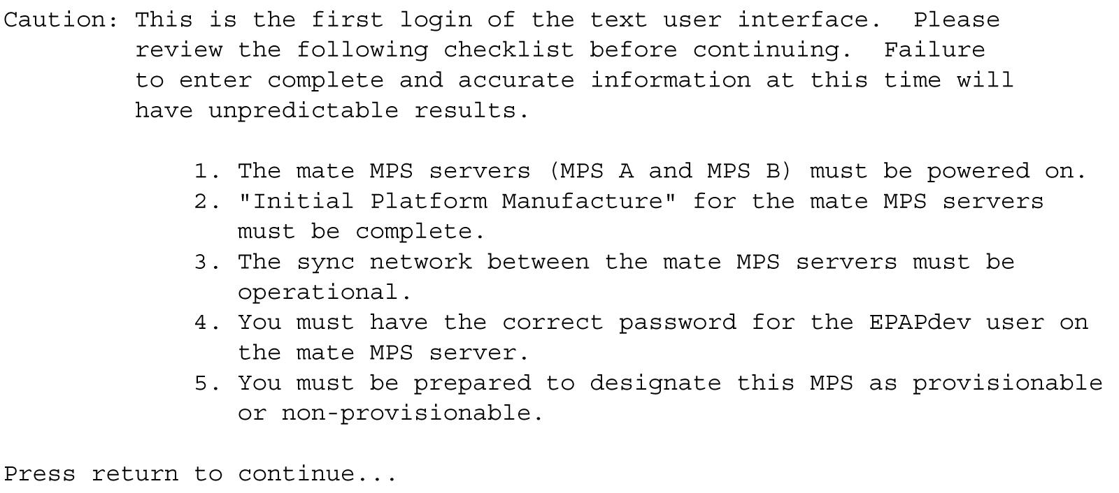
If all five criteria above are not met, the configuration cannot proceed. Ensuring that the MPS servers are powered on requires a visual check. If the Initial Platform Manufacture is not complete, the configuration cannot proceed; the user is also notified if the sync network is not operational.
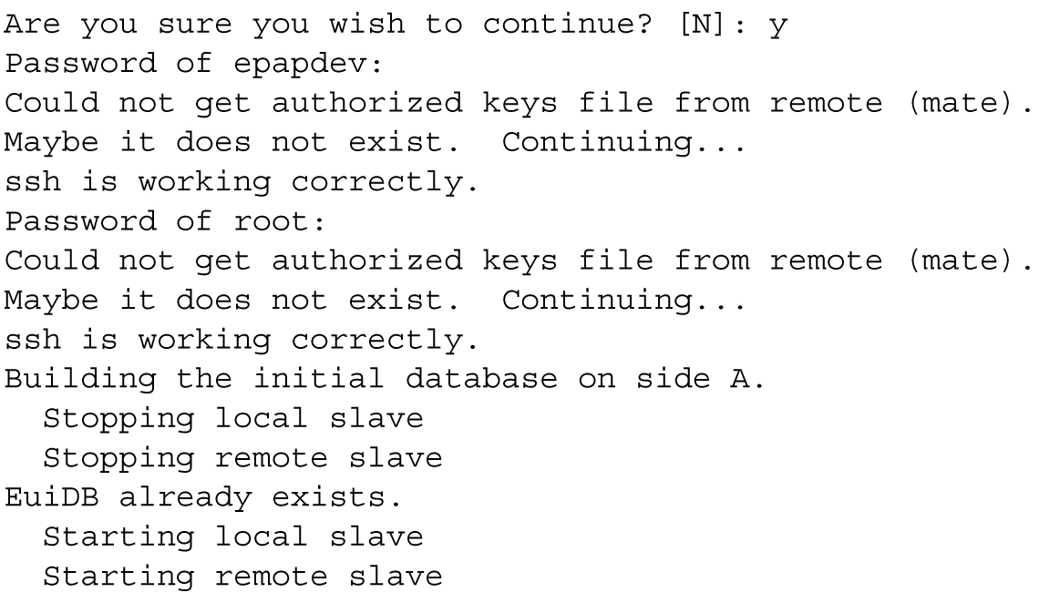
When the five criteria are met, press Return and the process resumes. Figure 5-3 shows the continuation of the screen information. The installer enters y if the installation is to continue.
Figure 5-3 Initial Configuration Continues
Note:
Review the information required for the following section in Required Network Address Information. Make certain all required information is obtained and recorded in the tables provided.
Next, the installer declares the MPS to be provisionable or non-provisionable, as shown in Figure 5-4. The example illustrates this MPS as a provisionable MPS.
Figure 5-4 Designating Provisionable or Non-Provisionable MPS

Next, the installer is prompted for the
epapdev user password on the mate MPS
server.
Figure 5-5
shows sample output that is generated after the correct password is entered.
Figure 5-5 Entering the
epapdev Password
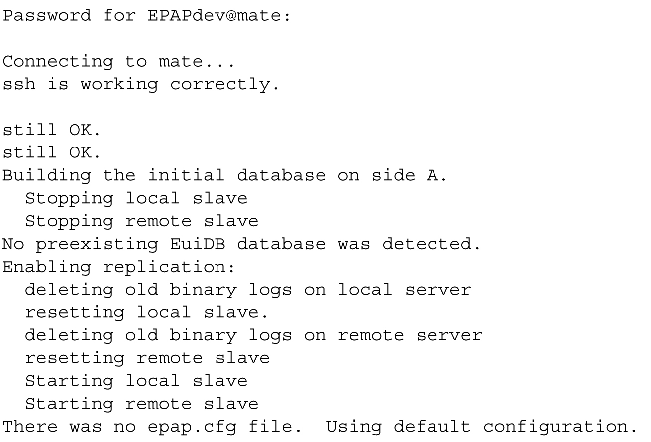
The Configuration Menu appears for the first time.
EPAP Configuration Menu
As shown below, a report and the test-based EPAP
Configuration Menu appear. The epapconfig user can now begin configuring the MPS local and remote
servers.
EPAP A Configuration Menu
/-----EPAP Configuration Menu----------\
/----------------------------------------\
|  1 | Display Configuration             |
|----|-----------------------------------|
|  2 | Configure Network Interfaces Menu |
|----|-----------------------------------|
|  3 | Set Time Zone                     |
|----|-----------------------------------|
|  4 | Exchange Secure Shell Keys        |
|----|-----------------------------------|
|  5 | Change Password                   |
|----|-----------------------------------|
|  6 | Platform Menu                     |
|----|-----------------------------------|
|  7 | Configure NTP Server              |
|----|-----------------------------------|
|  8 | PDB Configuration Menu            |
|----|-----------------------------------|
|  9 | Security                          |
|----|-----------------------------------|
| 10 | SNMP Configuration                |
|----|-----------------------------------|
| 11 | Configure Alarm Feed              |
|----|-----------------------------------|
| 12 | Configure Query Server            |
|----|-----------------------------------|
| 13 | Configure Query Server Alarm Feed |
|----|-----------------------------------|
| 14 | Configure SNMP Agent Community    |
|----|-----------------------------------|
| 15 | DB Architecture Menu              |
|----|-----------------------------------|
|  e | Exit                              |
\----------------------------------------/

Enter Choice:
EPAP B Configuration Menu
/-----EPAP Configuration Menu----------\
/----------------------------------------\
|  1 | Display Configuration             |
|----|-----------------------------------|
|  2 | Configure Network Interfaces Menu |
|----|-----------------------------------|
|  3 | Set Time Zone                     |
|----|-----------------------------------|
|  4 | Exchange Secure Shell Keys        |
|----|-----------------------------------|
|  5 | Change Password                   |
|----|-----------------------------------|
|  6 | Platform Menu                     |
|----|-----------------------------------|
|  7 | Configure NTP Server              |
|----|-----------------------------------|
|  8 | PDB Configuration Menu            |
|----|-----------------------------------|
|  9 | Security                          |
|----|-----------------------------------|
| 10 | SNMP Configuration                |
|----|-----------------------------------|
| 11 | Configure Alarm Feed              |
|----|-----------------------------------|
| 12 | Configure Query Server            |
|----|-----------------------------------|
| 13 | Configure Query Server Alarm Feed |
|----|-----------------------------------|
| 14 | Configure SNMP Agent Community    |
|----|-----------------------------------|
| 15 | DB Architecture Menu              |
|----|-----------------------------------|
|  e | Exit                              |
\----------------------------------------/

Enter Choice:
To choose a menu item, enter the number or letter of the
menu item at the
Enter Choice prompt and press
Return.
Note:
When exiting fromepapconfig menu, the EPAP GUI will be
terminated for a while and will be automatically restored.
Display Configuration
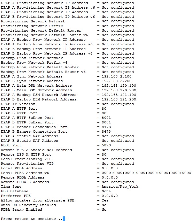
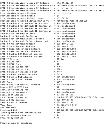
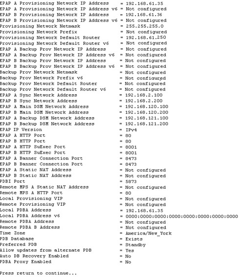
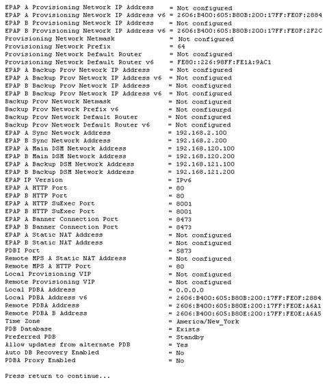
The Display Configuration option 1 displays a configuration of the EPAP. The following figure shows an example report:
Figure 5-6 Example of Configuration Report When the EPAP is Not Configured
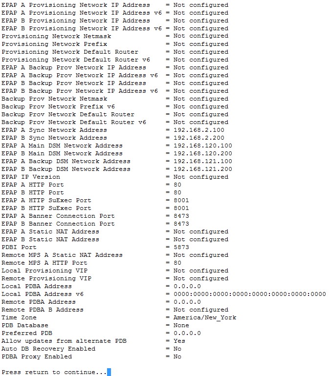
Addresses that you choose should not conflict with your internal network addresses. The class C networks you choose should not conflict with the class C network used in your network scheme. Table 5-6 shows an example of IP addresses that could be used in the configuration process.
Table 5-6 Sample IP Addresses Used in Configuration
|
Provisioning Network Information |
MPS EAGLE A (Local) IP Addresses |
MPS EAGLE B (Remote) IP Addresses |
|
EPAP A Provisioning Network IP Address (MPS A) |
192.168.61.119 |
192.168.61.90 |
|
EPAP B Provisioning Network IP Address (MPS B) |
192.168.61.120 |
192.168.61.91 |
|
Network Net Mask |
255.255.255.0 |
255.255.255.0 |
|
Default Router |
192.168.61.250 |
192.168.61.250 |
5.3.1 Configure Network Interfaces Menu
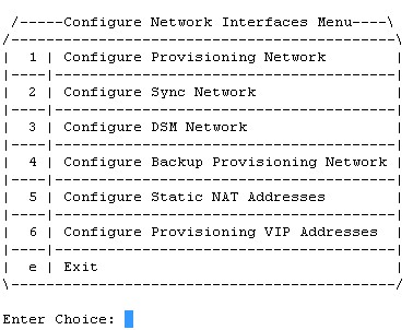
The Configure Network Interfaces Menu option 2 of the Configuration Menu displays the submenu shown in Figure 5-7. It supports the configuration of all the network interfaces for the EPAP.
Figure 5-7 Configure Network Interfaces Menu
Configure Provisioning Network
The Configure Provisioning Network option 1 of the Configure Network Interfaces Menu configures the EPAP provisioning network. With EPAP 16.1, the user is able to configure an IP address, net mask, and default router IP address when using an IPv4 address, and an IP address, Prefix and default router when using an IPv6 address. This information allows the EPAP to communicate with an existing customer network.
Note:
127.0.0.1 is not a valid IP address for this operation. 0.0.0.0 is a valid IP address and can be used to reset the VIP/backup provisioning IP address.Note:
You must configure these IP addresses. Obtain the values for the IP address, netmask, and default router from the customer’s Information Services department. Record the values in the four tables in Required Network Address Information.In response to each prompt, you can enter a dotted decimal IP address or press Return to leave the current value unchanged. The current value is shown in brackets after the prompt text. See Figure 5-8 for the option 1 configuration.
Figure 5-8 Configure Provisioning Network Menu

Note:
Take care in configuring the IP information. Incorrect information can prevent the EPAP from accepting provisioning data and establishing remote EPAP user interface connections over the customer network.Configure DSM Network
The Configure DSM Network option 3 of the Configure Network Interfaces Menu prompts you for the EPAP DSM network IP addresses. This information allows the EPAP to communicate with the main and backup DSM networks.
Note:
127.0.0.1 is not a valid IP address for this operation. 0.0.0.0 is a valid IP address and can be used to reset the VIP/backup provisioning IP address.Note:
Unless there is a known network address conflict, the installer can bypass option 3.Note:
It is strongly advised not to change the DSM network subnet (IP addresses), if not absolutely necessary.In response to each prompt, you can enter a dotted decimal IP address or press Return to leave the current value unchanged (the current value is shown in brackets after the prompt text).
See Network Connections for a description of EPAP network IP address assignments. See Figure 5-9 for the option 3 output.
Figure 5-9 Configure DSM Network

Note:
Take care in configuring the IP information. Incorrect information will prevent the EPAP from communicating with the EAGLE.Configure Backup Provisioning Network
The Configure Backup Provisioning Network option 4 of the Configure Network Interfaces Menu prompts you for the EPAP Backup Provisioning Network IP addresses. This information allows the EPAP to communicate with the backup provisioning network. With EPAP 16., the user is able to configure an IP address, net mask, and default router IP address when using an IPv4 address, and an IP address, Prefix and default router when using an IPv6 address. In response to each prompt, enter a dotted decimal IP address.
See Network Connections for a description of EPAP network IP address assignments. See Figure 5-10 for the option 4 output.
Figure 5-10 Configure Backup Provisioning Network

Note:
127.0.0.1 is not a valid IP address for this operation. 0.0.0.0 is a valid IP address and can be used to reset the VIP/backup provisioning IP address.Note:
Take care in configuring the IP information. Incorrect information will prevent the EPAP from communicating with the Backup Provisioning Network.Configure Forwarded Ports
The Configure Forwarded Ports option 5 of the Configure Network Interfaces Menu provides the functionality to configure EPAP ports for the Web UI.
Note:
127.0.0.1 is not a valid IP address for this operation. 0.0.0.0 is a valid IP address and can be used to reset the VIP/backup provisioning IP address.Each numbered item of the Configure Forwarded Ports menu allows the user to specify a port number used for remote access to the MPS.
This information should be received from the customer for the MPS and recorded in Table 5-1 and Table 5-2 .
Configure Static NAT Addresses
The Configure Static NAT Addresses option 6 from the Configure Network Interfaces Menu provides the functionality to configure the static NAT addresses of the EPAP.
Note:
Only IPv4 is supported with Static NAT addresses.Each numbered item of the Configure Static NAT Addresses menu allows the user to specify an IP Address used outside of the firewall for remote access to the MPS. The following Figure 5-11 shows an example of a resulting prompt.
Note:
127.0.0.1 is not a valid IP address for this operation. 0.0.0.0 is a valid IP address and can be used to reset the VIP/backup provisioning IP address.Figure 5-11 Configuring NAT Addresses Prompt

Configure Provisioning VIP Addresses
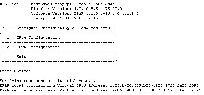
The Configure Provisioning VIP Addresses option 7 from the Configure Network Interfaces Menu provides the functionality to configure the PDBA Proxy feature.
The user must enter the VIP address for the local PDBA (MPS-A) and the remote PDBA using either an IPv4 or IPv6 address. The following figure shows an example of the option 7 output.
Figure 5-12 Configure Provisioning VIP Address
Note:
127.0.0.1 is not a valid IP address for this operation. 0.0.0.0 is a valid IP address and can be used to reset the VIP/backup provisioning IP address.5.3.2 Set Time Zone
The Select Time Zone option 3 prompts you for the
time zone to be used by the EPAP. The time zone can be the zone where the EPAP is
located, Greenwich Mean Time, or another zone that is selected by the customer to meet
the needs of the system.
Note:
The value for the time zone should be obtained from the customer’s Information Services department. The default value for the time zone is “US/Eastern”.To select a file in one of the subdirectories, enter a relative path name (such as “US/Eastern”) in response to the prompt. See List of Time Zones for the option 3 output.
You must enter a valid UNIX time zone file name. Alternatively, to display a complete list of the valid time zones, simply press Return in response to the prompt and all valid time zone names are displayed. See List of Time Zones for the list that appears when you press the Return key or enter invalid time zone file name.
The time zone change does not take effect until the next time the MPS is rebooted. The Reboot MPS menu is described in Reboot the MPS.
5.3.3 Exchange Secure Shell Keys
The Exchange
Secure Shell Keys option 4 accesses the Exchange Secure
Shell Keys menu. This menu is used to enable connections between local and remote EPAPs. The EPAPs exchange encryption keys are required to run the secure shell.
The exchange normally occurs automatically during EPAP initialization. Use this menu item only if the exchange must be performed manually.
See Figure 5-13 for the option 4 output.
Figure 5-13 Exchange Secure Shell Keys Menu
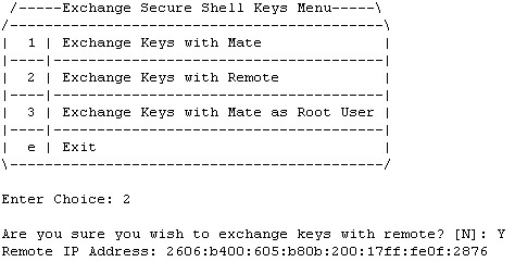
Option 1 is used for the initial configuration. Option 2 is used to do a reload of the RTDB from the remote server. Option 3 is required before using the PDBA Proxy feature. Before doing a reload from the remote server, you must exchange keys with the remote server. The sub menu "Exchange Keys with Remote" allows the user to exchange keys with the remote server. The remote server IP will be either IPv4 or IPv6.
The epapconfig user must know the password for the epapdev@mate. The notification “ssh is working correctly” in the following figure confirms the “ssh” (i.e., secure shell) exchange of keys has completed successfully.
See Figure 5-14 for the Option 1 output.
Figure 5-14 Exchange Secure Shell Keys Output

5.3.4 Change Password
The Change Password option
5
changes the text-based
user interface password for the epapconfig login name
for both MPS A and B.
See Figure 5-15 for the option 5 output.
Figure 5-15 Change Password

5.3.5 Platform Menu
The EPAP Platform Option 6 accesses the Platform menu so that the epapconfig user can access and manage the platform functions shown in the menu. See Figure 5-16 for the option 6 output.
Figure 5-16 Platform Menu Output
 /-----EPAP Platform Menu-\
/--------------------------\
|  1 | Initiate Upgrade    |
|----|---------------------|
|  2 | Reboot MPS          |
|----|---------------------|
|  3 | MySQL Backup        |
|----|---------------------|
|  4 | RTDB Backup         |
|----|---------------------|
|  5 | PDB Backup          |
|----|---------------------|
|  e | Exit                |
\--------------------------/

Enter Choice:
Initiate Upgrade
The Initiate Upgrade option 1 of the EPAP Platform Menu initiates an upgrade on the selected EPAP. For upgrade output or procedures, contact Oracle Communications Technical Services; refer to My Oracle Support.
Reboot MPS
The Reboot MPS option 2 of the EPAP Platform Menu initiates a reboot of either MPS or both. The default, as shown below, is BOTH.
Note:
epapconfig user can abort rebooting the MPS by pressing the Escape key at the displayed prompt.Reboot MPS A, MPS B or [BOTH]:Note:
Rebooting the MPS stops all EPAP processes, and databases cannot be updated until the MPS has completely booted.
MySQL Backup
The MySQL Backup option 3 of the EPAP Platform Menu backs up the MySQL database. The output is shown below.
Note:
EPAP software is running. Stop it? [N]: y Are you sure you want to back up the MYSQL on MPS? [N]: y Backing up the NPDB...RTDB Backup
The RTDB Backup option 4 of the EPAP Platform Menu backs up the RTDB database. The output is shown below.
EPAP software is running. Stop it? [N]: y

Are you sure you want to back up the RTDB database on MPS A to "/var/TKLC/epap/free/rtdbBackup_<hostname>_<timestamp>_v<RTDB version>.<No. of RTDB files>.bkp.tar.gz"? [N]: y

Successfully started backup of RTDB.
Status will be displayed on the GUI banner.
Note:
EPAP software must be stopped, or the RTDB backup will abort and return to the EPAP Platform Menu.
PDB Backup
The PDB Backup option 5 of the EPAP Platform Menu backs up the PDB database. The output is shown below
Are you sure you want to backup the PDB to /var/TKLC/epap/free/pdbBackup_<hostname>_<timestamp>_DBBirthdate_<birthdate>GMT_DBLevel_<dblevel>_v<PDB version>.<No. of ibdata files in the backup>.bkp.tar.gz? [N]: Y

Successfully started backup of PDB.
Status will be displayed on the GUI banner.
Note:
PDB only maintains a single copy of backup file. If the backup file is already present, the PDB Backup already exists in free directory error message is displayed. Therefore it is required to transfer PDB backup file to remote server using Configure File Transfer as described in section Configure File Transfer or manually by using sftp.EPAP Platform Menu Exit
The Exit option e of the EPAP Platform Menu exits from the EPAP Platform Menu and returns to the EPAP Configuration Menu.
5.3.6 Configure NTP Server Menu
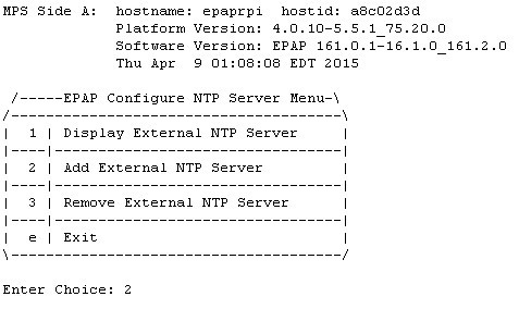
The Configure NTP Server Menu option 7 allows for the display, addition, and removal of an external NTP server. As of EPAP 16.1, the user is able to add/remove external NTP servers using both IPv4 and IPv6 addresses.
- The user is allowed to configure IPv4 only remote system address
- The user is allowed to configure IPv6 only remote system address
- On dual stack - the user is allowed to configure IPv4 or IPv6 remote system address
See the following figure for the option 9 output:
Figure 5-17 Configure NTP Server Menu
Display External NTP Server
The Display External NTP Server option 1 of the Configure NTP Server Menu displays External NTP Server information. If a server is present, the server name and IP address are displayed. If an NTP Server is not present, the following is displayed.
There are no External NTP Servers.
Press return to continue...
Add External NTP Server
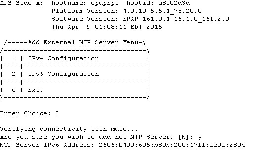
The Add External NTP Server option 2 of the Configure NTP Server Menu adds an External NTP Server. The following figure shows an example of the addition of an External NTP Server.
Note:
The IP address must be a valid address for an External NTP Server.
Figure 5-18 Add NTP Server Menu
Remove External NTP Server
The Remove External NTP Server option 3 of the Configure NTP Server Menu removes an External NTP Server. If a server is present, selecting the Remove External NTP Server removes the server. If an NTP Server is not present, the following appears.
There are no External NTP Servers.
Press return to continue...
5.3.7 PDB Configuration Menu
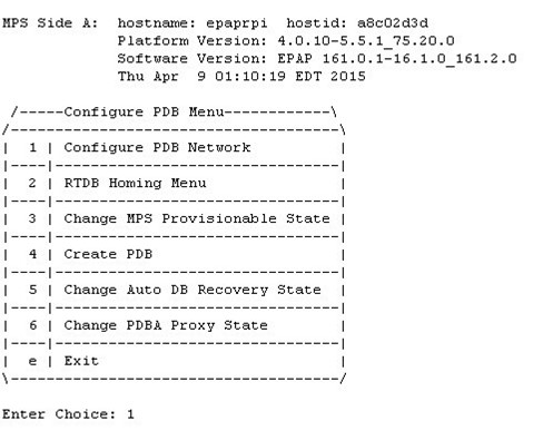
The PDB Configuration Menu option 8 supports configuring the PDB network, homing of the RTDBs, changing the MPS provisionable status, creating the PDB, and enabling the Automated Database Recovery and PDBA Proxy features. Beginning with EPAP 16.1, the user is able to configure both IPv4 and IPv6 addresses for a PDB address. See Figure 5-19 for the option 8 output.
Figure 5-19 Configure PDB Menu
Configure PDB Network
The Configure PDB Network option 1 of the Configure PDB Menu identifies the provisioning network interface addresses of the remote PDBs. For provisionable MPSs, the local provisioning interface address is known. The configuration user interface prompts for only the remaining remote address. Non-provisionable MPSs prompt for both remote PDB addresses.
Provisionable MPSs then prompt for the password of the
epapdev user at the remote PDB
address. The following table shows Remote PDBA configuration use cases:
Table 5-7 Remote PDBA Configuration Use Cases
| Site 1 Configuration | Site 2 Configuration | ||
| IPv4 Only | IPv6 Only | Dual Stack | |
| IPv4 Only | Allowed | Not Allowed | Only IPv4 IP allowed for remote PDBA |
| IPv6 Only | Not allowed | Allowed | Only IPv6 IP allowed for remote PDBA |
| Dual Stack | Only IPv4 IP allowed for remote PDBA | Only IPv6 IP allowed for remote PDBA | IP version should be the same on both sites (either IPv4 or IPv6)* |
* If both sites are configured in dual stack, the configuration must be kept consistent at both sites. The user is responsible for the maintenance of this configuration.
Note:
If you accept the ‘No’ default (that is, not stopping EPAP software and the PBA from running), the configuration process will abort. The following examples show the responses required to continue the initial configuration.RTDB Homing Menu
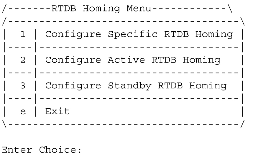
The RTDB Homing Menu option 2 of the Configure PDB Menu provides a menu to configure specific and active homing of RTDBs to the PDBAs. For more information about active and specific homing, refer to Selective Homing of EPAP RTDBs. Figure 5-20 shows the option 2 output.
Figure 5-20 RTDB Homing Menu
Configure Specific RTDB Homing
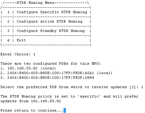
The Configure Specific RTDB Homing option 1 of the RTDB Homing Menu sets the RTDB homing policy to specific and configures the address of the preferred PDB.
This configuration cannot be completed until the PDB network has been configured. See Configure PDB Network. Provisionable sites indicate the address of the local PDB with the text (local) and that site is the default value for the preferred PDB.
The text-based User Interface prompts for the preferred PDB. When the choice is selected, the text confirms the choice and identifies the selection is 'specific' homing. When the EPAP is configured in a dual stack configuration, the PDBA also has both the IPs, one in IPv4 format and the other in IPv6 format. By default, the RTDB Homing Policy is set to the PDBA IPv6 IP. If the user wants to change the RTDB homing policy to the PDBA IPv4 IP, then the Configure Specific RTDB Homing menu option must be used.
Figure 5-21 RTDB Homing Policy Configuration
Configure Active RTDB Homing
The Configure Active RTDB Homing option 2 of the RTDB Homing Menu sets the RTDB homing policy to active and configures whether to allow updates from the alternate PDB. The prompt selection must be confirmed if updates are not allowed from the standby PDB.
The text-based User Interface prompts for whether updates are to be allowed from the standby MPS. When the choice is entered, the text confirms the choices and identifies the selection is ‘active’ homing and whether updates are allowed from the PDB of the standby MPS.
EPAP software and PDBA are running. Stop Them? [N] y


In the event that the active PDB is unavailable, should updates be allowed to the RTDBs from the standby MPS? [Y]: N

Caution: If this option is selected, the standby PDB will not provision the RTDBs at this site in the event that the active PDB is not available.

Are you sure you want to disallow updates to the RTDBs from the standby PDB? Y

The RTDB Homing policy is set to 'active' and will not allow updates from the standby PDB.
Configure Standby RTDB Homing
The Configure Standby RTDB Homing option 3 of the RTDB Homing Menu sets the RTDB homing policy to standby and configures whether to allow updates from the active PDB. The prompt selection must be confirmed if updates are not allowed from the active PDB.
The text-based User Interface prompts for whether updates are to be allowed from the active MPS. When the choice is entered, the text confirms the choices and identifies the selection is ‘standby’ homing and whether updates are allowed from the PDB of the active MPS.
EPAP software and PDBA are running. Stop Them? [N] y
In the event that the standby PDB is unavailable, should updates be allowed to the RTDBs from the active MPS? [Y]: N
Caution: If this option is selected, the active PDB will not provision the RTDBs at this site in the event that the standby PDB is not available.
Are you sure you want to disallow updates to the RTDBs from the active PDB? Y
The RTDB Homing policy is set to 'standby' and will not allow updates from the active PDB.
Change MPS Provisionable State
The Change MPS Provisionable State option 3 of the Configure PDB Menu specifies this site as provisionable or non-provisionable. For more information about these states, refer to Provisioning Multiple EPAPs Support. This command toggles the states between provisionable and non-provisionable.
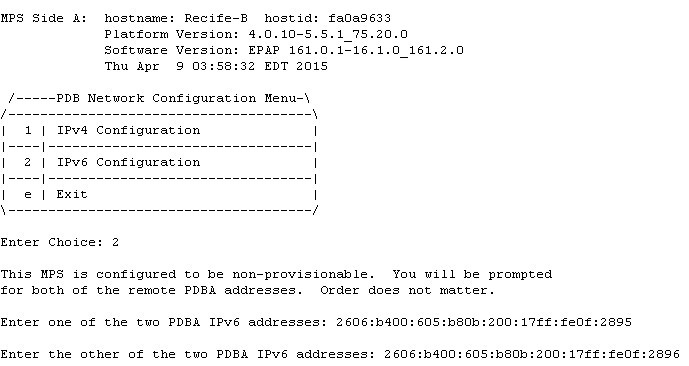
See EPAP Configuration Menu for the prompt that is displayed for this menu item. To complete this configuration, the user is prompted to configure the remote PDBA addresses from which the non-provisionable EPAP takes the updates. The user is allowed to specify either the IPv4 or the IPv6 address for the remote PDBA:
Figure 5-22 Configure PDB Network for Provisionable MPS
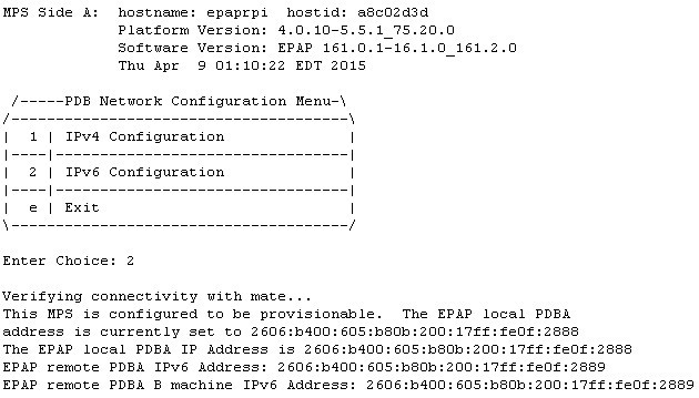
Figure 5-23 Configure PDB Network for Non-Provisionable MPS
Create PDB
The Create PDB option 4 of the Configure PDB Menu creates and initializes a Provisioning Database (PDB) for the EPAP.
Caution:
PDB not created Caution: This MPS has not been completely configured. Applications may not run until all required parameters are entered through the text user interface. Choose "Display Configuration" for a list of configurable parameters and their settings. Press return to continue...Change Auto DB Recovery State
The Change Auto DB Recovery State option 5 of the Configure PDB Menu is used to enable the Automated Database Recovery feature.
The text-based User Interface prompts with this text:
Auto DB Recovery is currently DISABLED.
Do you want to ENABLE Auto DB Recovery? [N]:
Change PDBA Proxy State
The Change PDBA Proxy State option 6 of the Configure PDB Menu is used to enable the PDBA Proxy feature.
The text-based User Interface prompts with this text:
PDBA PROXY is currently DISABLED.
Do you want to ENABLE PDBA Proxy? [N]:
PDB Configuration Menu Exit
The Exit option e of the PDB Configuration Menu exits and returns to the EPAP Configuration Menu, shown in EPAP Configuration Menu.
5.3.8 Security
Figure 5-24 EPAP Configuration Menu
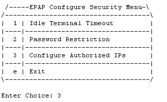
The Security Menu option 9 provides access to configure the Idle Terminal Timeout and the password restrictions for EPAP system users. See Figure 5-25 for the option 8 output.
Figure 5-25 EPAP Configure Security Menu
The submenu Configure Authorized IPs allows the user to configure the authorized IPs for the EPAP. The functionality of this menu is the same as the GUI menu .
Figure 5-26 EPAP Configure Authorized IPs Menu

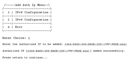
The Add Authorized IP menu option allows the user to add a new IP address, either in IPv4 or IPv6 format, to the list of the authorized IP addresses. The authorized IP version is independent of the EPAP network configuration. The authorized IP list can have a mix of the IPv4 and IPv6 IPs:
Figure 5-27 Add Authorized IP
The Display Authorized IPs menu option displays the list of authorized IPs. It displays all the configured IPs:
Figure 5-28 Display Authorized IPs
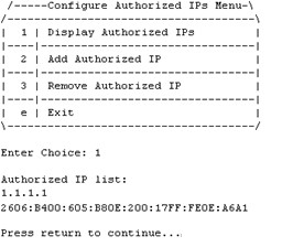
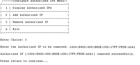
The Remove Authorized IP screen allows the user to remove an IP address from the list of authorized IP addresses. The screen has no change for the IP version. The "IP to remove" field accepts both type of IPs, either IPv4 or IPv6:
Figure 5-29 Remove Authorized IP
Idle Terminal Timeout
The Idle Terminal Timeout, option 1 of the Figure 5-25 displays the submenu shown below. This menu provides access to configure the Idle Terminal Timeout Security options. Option 1 of the menu displays the configured idle terminal timeout. Option 2 of the menu provides the interface to set the Idle Terminal Timeout.
The EPAP terminal will logout the user if the terminal remains idle for the configured amount of time. The Idle Terminal Timeout limit will be within the range of 0 - 9999 (seconds), both inclusive, where 0 specifies no timeout. If the idle terminal timeout is not set, then the system default will apply i.e., no timeout.
Note:
The idle terminal timeout is not applicable to the system users who either have restricted shell or do not have their own shell. This behavior is valid for system users like appuser, platcfg, and epapconfig.
 /-----Configure Idle Terminal Timeout Security Menu-\
/-----------------------------------------------------\
|  1 | Display Idle Terminal Timeout                  |
|----|------------------------------------------------|
|  2 | Configure Idle Terminal Timeout                |
|----|------------------------------------------------|
|  e | Exit                                           |
\-----------------------------------------------------/
PDBI Idletimeout
The PDBI idletimeout parameter in Connect() request allows the client to specify the amount of time that the connection can remain idle before the PDBA terminates it.
This idletimeout parameter is configurable on EPAP via the uiEdit variable "PDBI_IDLE_TIMEOUT". The default value of this variable is zero (0) and the valid range is 0 to 2678400 (60*44640) seconds.
The idletimeout parameter in the PDBI Connect() request overrides the configured value on EPAP for that connection instance.
Password Restriction
The Password Restriction, option 2 of Figure 5-25 displays the submenu shown below. Option 1, System Default, provides the interface to configure password restrictions for the System Default, i.e. the restrictions shall apply for all new system users only. Option 2, Per User, provides the interface to configure password restrictions per user basis.
 /-----Configure Password Restriction Menu-\
/------------------------------------------ \
|  1 | System Default                       |
|----|--------------------------------------|
|  2 | Per User                             |
|----|--------------------------------------|
|  e | Exit                                 |
\-------------------------------------------/
System Default
Option 1 of the above menu displays the submenu shown below.
In the below mentioned submenu, Option 1 displays the password restrictions configured for the new system users. Options 2 to 5 provide interface to set the password restrictions for the new system users.
If the password restrictions are not configured, then the default password restrictions is applied to the existing and new system users.
 /-----Configure Password Restriction Menu-----------------------------------\
/-----------------------------------------------------------------------------\
|  1 | Display Password Restriction Configuration                             |
|----|------------------------------------------------------------------------|
|  2 | Min no of days allowed between password changes                        |
|----|------------------------------------------------------------------------|
|  3 | Max no of days a password may be used                                  |
|-----------------------------------------------------------------------------|
|  4 | Minimum acceptable Password size                                       |
|-----------------------------------------------------------------------------|
|  5 | Number of days that a user will be warned before his password expires  |
|--- |------------------------------------------------------------------------|
|  e | Exit                                                                   |
\-----------------------------------------------------------------------------/
Per User
If password restrictions are configured per user basis, then the user is required to enter the username and password of the user for which password restriction is to be applied, as shown below.
 /-----Configure Password Restriction Menu-\
/------------------------------------------ \
|  1 | System Default                       |
|----|--------------------------------------|
|  2 | Per User                             |
|----|--------------------------------------|
|  e | Exit                                 |
\-------------------------------------------/

Enter Choice: 2
Enter username:
Enter password for user:
After the successful authorization of the entered username, the below mentioned submenu is displayed.
Option 1, Display Password Restriction Configuration, displays the password restrictions configured for the specified system user. Options 2 to 4 provide the interface to set the password restrictions for the specified system user.
 /-----Configure Password Restriction Menu-----------------------------------\
/-----------------------------------------------------------------------------\
|  1 | Display Password Restriction Configuration                             |
|----|------------------------------------------------------------------------|
|  2 | Min no of days allowed between password changes                        |
|----|------------------------------------------------------------------------|
|  3 | Max no of days a password may be used                                  |
|-----------------------------------------------------------------------------|
|  4 | Number of days that a user will be warned before his password expires  |                                       |
|-----------------------------------------------------------------------------|
|  e | Exit                                                                   |
\-----------------------------------------------------------------------------/
Password Restriction Parameters
- Min no of days allowed between password changes
- The min no. of days allowed between password changes parameter prevents the system user from changing the password before the configured time. If the value is not set, then the system default of 0 days is used. the value must be within the range of 1 - 180, both inclusive. The value must be less than or equal to the maximum number of days a password may be used.
- Max no of days a password may be used (Password Aging)
- The maximum number of days a password may be used (password aging) determines the number of days for which the current password of the system user works. Once the password expires, the user is required to change to a new password. The user cannot login with the expired password. If the value is not set, then the system default of 99999 days is used. If configured, the EPAP system password aging must be within the range of 1 - 180, both inclusive. When configuring password aging, only a value greater than or equal to the current value of minimum number of days a password may be used, is acceptable.
- Number of days that a user will be warned before his password expires
- System users are warned N days before their passwords expire. The N value is configured using the Number of days that a user will be warned before his password expires parameter. If the password warning days is not set, then the system default of 7 days is used. A value of 0 means warning is given only on the day of password expiration. A value of -1 means no warning is given. When configuring the password warning days for EPAP system users, only a value less than or equal to the difference between current password aging and minimum number of days allowed between password changes settings, is acceptable.
- Minimum acceptable Password size
- The minimum password length configured is applicable for all existing and new system users. The allowed minimum length for password is in the range of 8 to 80, both inclusive. If minimum password length is not set, then the system default of 5 is used.
Password Change for System Users
The appuser users use the passwd command provided by the Operating System. If changing a password using the passwd command, then the Linux PAM credit rules are used.
The system user epapconfig uses the option provided in the EPAP Configuration Menu. Linux PAM rules are not applicable while changing the password for the epapconfig user. Only the configured minimum password length applies.
Note:
If the password for the appuser or epapconfig user is changed by the root user, the appuser or epapconfig user will be prompted to change the password again.5.3.9 SNMP Configuration Menu
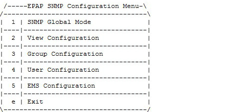
The SNMP Configuration option 10 is used to support all configuration related to SNMPv2c and SNMPv3. See Figure 5-30 for the option 10 output.
Figure 5-30 EPAP SNMP Configuration Menu
SNMP Global Mode
EPAP supports three SNMP global modes: SNMPv2c, SNMPv3, and both. The EPAP user is able to update or view the global mode in the menu by choosing option 1).
Figure 5-31 SNMP Global Mode Menu

Update SNMP Global Mode Menu
The EPAP user is able to update the global mode using option 2.
Figure 5-32 Update SNMP Global Mode Menu

If SNMPv2c (option 2) mode is enabled, then EPAP only supports SNMPv2c:
- EPAP forwards SNMPv2c format traps only to the configured EMS(s) that support v2c.
- EPAP only allows the addition of any new EMS supporting v2c to be configured. Existing EMS(s) are prohibited from modification to support v3.
- Prior to the mode change to SNMPv3 only, all configured EMS(s) supporting v2c will be removed.
If SNMPv3 (option 1) mode is enabled (recommended), then the EMS only supports SNMP version 3:
- EPAP forwards SNMPv3 format traps only to the configured EMS(s) that support v3.
- EPAP only allows the addition of any new EMS supporting v3 to be configured. Existing v3-supporting EMS(s) are prohibited modification to support v2c.
- Prior to the mode change to SNMPv2c ONLY, all configured EMS(s) supporting v3 will be removed.
If Both (option 3) mode is enabled, then EPAP supports both SNMPv2c and SNMPv3.
- EPAP forwards traps to all the configured EMS(s) that support v2c or v3.
- EPAP allows the addition of new or updated EMS(s) supporting v2c or v3.
SNMPv3 Access View Configuration Menu
To support View-Based Access Control Mode for SNMPv3, View Configuration, option 2 under the SNMP Configuration menu, supports sub-menus Add, Delete, Update, Display in order to manage Access Views. The View menu is only accessible if SNMP Global Mode is configured as SNMPv3 ONLY or Both. If SNMPv2c only mode is enabled and the EPAP user tries to access the View menu, the "Error: SNMPv3 View must NOT be configured for SNMP v2c Mode" is displayed.
Figure 5-33 View Configuration Menu
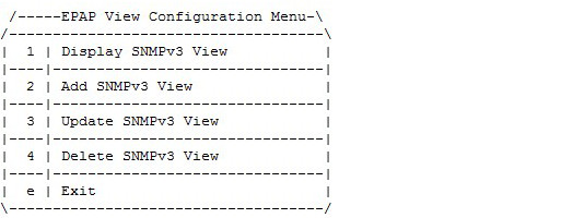
The EPAP user is able to add a new View using option 2 under the View Configuration menu, as displayed in Figure 5-34. The default view is not be shown during add/update/delete, as no write operation is allowed on it.
Figure 5-34 Add SNMPv3 View

The EPAP user is able to display the configured View using option 1 of the View Configuration menu, as displayed in Figure 5-35:
Figure 5-35 Display SNMPv3 View
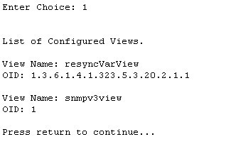
The EPAP user is able to update the configured View using option 3 under the View Configuration menu, as displayed in Figure 5-36. The already configured OID associated with corresponding view name is shown in square brackets:
Figure 5-36 Update SNMPv3 View
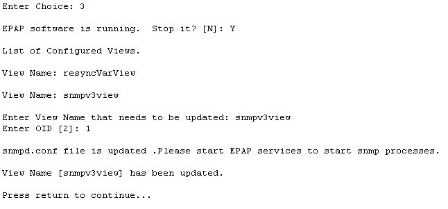
The EPAP user is able to delete the view using option 4 under the View Configuration menu, as displayed in Figure 5-37:
Figure 5-37 Delete SNMPv3 View
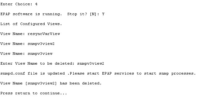
Note:
- View name is non-empty and unique.
- The length of View name cannot be more than 32 characters.
- View Name contains only alphanumeric characters and is case insensitive when being configured.
- OID to be associated with the View is mandatory.
- A View that is associated to any group cannot be deleted.
SNMPv3 Group Management
To support User-Based Security Mode for SNMPv3, Group Configuration, option 3 under the SNMP Configuration menu, supports sub-menus Add, Delete, Update, Display in order to manage Groups. The Group menu is only accessible if SNMP Global Mode is configured as SNMPv3 ONLY or Both. If SNMPv2c only mode is enabled and the EPAP user tries to access the Group menu, the "Error: SNMPv3 Group must NOT be configured for SNMP v2c Mode" is displayed.
Figure 5-38 Group Configuration Menu
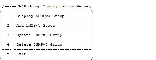
The EPAP user is able to add a new Groups using option 2 under the Group Configuration menu, as displayed in Figure 5-39. The default value of the security level "AuthPriv" is shown in square brackets:
Figure 5-39 Add SNMPv3 Group
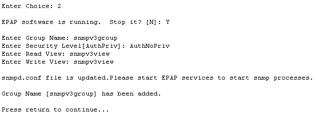
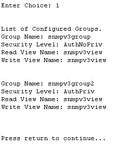
The EPAP user is able to display the configured Group using option 1 of the Group Configuration menu, as displayed in Figure 5-40:
Figure 5-40 Display SNMPv3 Group
The EPAP user is able to update the configured Groups using option 3 under the Group Configuration menu, as displayed in Figure 5-41. The already configured security level related to the corresponding Group is shown in square brackets; however, the read and write view is not shown in square brackets, as these are allowed to be empty:
Figure 5-41 Update SNMPv3 Group

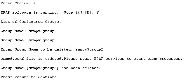
The EPAP user is able to delete the Groups using option 4 under the Group Configuration menu, as displayed in Figure 5-42:
Figure 5-42 Delete SNMPv3 Group
Note:
- Group name is non-empty and unique.
- The length of Group name cannot be more than 32 characters.
- View Name must contain only alphanumeric characters and is case insensitive when configured; however, during update, Group name is case sensitive.
- Security Level is mandatory. Valid values are noAuthNoPriv, AuthNoPriv, and AuthPriv.
- Read View is optional. Specify the View name spelled exactly as configured in the View Menu if added.
- Read View is configured if it is to be added to the Group.
- Write View is optional. Specify the View name spelled exactly as configured in the View Menu if added.
- Write View is configured if it is to be added to the Group
- A Group that associated to any user cannot be deleted.
SNMPv3 User Management
To support User-Based Security Mode for SNMPv3, User Configuration, option 4 under the SNMP Configuration menu, supports sub-menus Add, Delete, Update, Display in order to manage Users. The User menu is only accessible if SNMP Global Mode is configured as SNMPv3 ONLY or Both. If SNMPv2c only mode is enabled and the EPAP user tries to access the User menu, the "Error: SNMPv3 User must NOT be configured for SNMP v2c Mode" is displayed.
Figure 5-43 User Configuration Menu
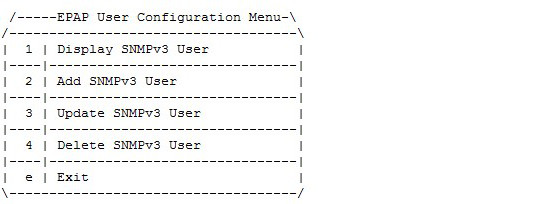
The User sub-menus are able to configure a user name, a group, and optional Privacy Protocol, Privacy Password, Authentication Protocol, and Authentication Password, depending on the security level configured for the chosen Group.
The EPAP services will be stopped through an interactive prompt menu every time the EPAP user initiates Add, Delete, or Update Group configuration.
The EPAP user is able to add a new User using option 2 under the User Configuration menu, as displayed in Figure 5-44. The password information is not visible to the EPAP user. The default value of the Authentication Protocol and Privacy Protocol will be shown in square brackets while adding a new User:
Figure 5-44 Add SNMPv3 User
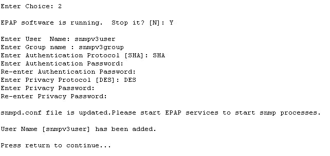
The Add SNMPv3 User is configured based on Group configuration. First, the Group Name values are validated against the Group configured. If no valid Group is found, the Add step fails with a corresponding error message. If the Group entered is validated, then the menu lists only the valid fields corresponding to the Group entered. If the security level configured for the chosen group is 'noAuthNoPriv', then the input fields for Authentication Protocol, Authentication Password, Privacy Protocol, and Privacy password will not be displayed. If the security level configured for the chosen group is 'AuthNoPriv', the input fields Priv Protocol and Priv Password will not be displayed. By default, DES is selected for the addition of a new User for an AuthPriv scenario.
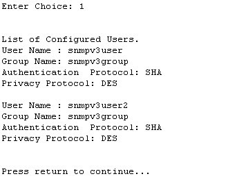
The EPAP user is able to display the configured Users using option 1 of the User Configuration menu, as displayed in Figure 5-45. The password information for the authentication protocol and privacy protocol is not displayed:
Figure 5-45 Display SNMPv3 User
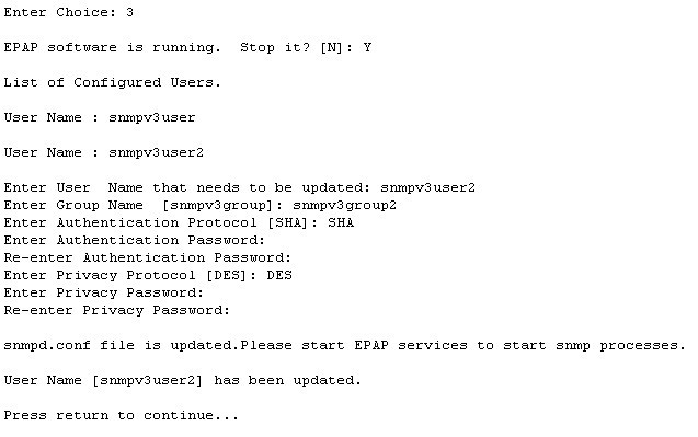
The EPAP user is able to update the configured Users using option 3 under the User Configuration menu, as displayed in Figure 5-46. The parameters already configured for the corresponding user will be shown in square brackets:
Figure 5-46 Update SNMPv3 User
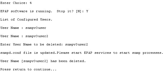
The EPAP user is able to delete the Usersroups using option 4 under the User Configuration menu, as displayed in Figure 5-47:
Figure 5-47 Delete SNMPv3 User
Note:
- Group name is non-empty and unique.
- The length of Group name cannot be more than 32 characters.
- User Name must contain only alphanumeric characters and is case insensitive when configured.
- Group must have been configured if it is to be added to the User.
- Group must be spelled in the exact case as configured in the Group menu.
- If the security level configured for the chosen group is 'noAuthNoPriv', then the input to Authentication Protocol, Authentication Password, Privacy Protocol and Privacy Password fields will not be displayed.
- If the security level configured for the chosen group is 'AuthNoPriv', then it is required to input the desired value for Authentication Protocol and provide a valid password in the Authentication Password field. The input to Privacy Protocol and Privacy Password fields are not required.
- If the security level configured for the chosen group is 'AuthPriv', then it is required to select the desired values for Authentication Protocol and Privacy Protocol fields and provide valid passwords in the Authentication Password and Privacy Password fields.
- Valid values for Auth Protocol is SHA as the default.
- Valid values for Priv Protocol are DES and AES; DES is the default.
- Auth and Priv password length must be between 8 and 255 inclusive.
- Auth and Priv password is stored in encrypted form in the DB.
- Only the following alphanumeric characters and special characters are allowed in Auth and Priv passwords: @, #, $, !
- A user associated to any EMS cannot be deleted.
- A default user "oracleuser" is for system use and will not be visible, added, edited, or deleted by customers through this menu.
5.3.9.1 Configure EMS Server
The EMS Configuration option 5 under the EPAP SNMP Configuration Menu allows the user to configure the EMS server using either an IPv4 or IPv6 address. The User Configuration sub-menus can be configured with an EMS host name, IP, Port, Heart Beat in seconds, and either Community or User, depending on the global mode set in SNMP Global Mode. If the Global Mode is SNMPv2c ONLY, the input field "User" will not be displayed.
The EPAP supports the configuration of maximum 5 EMS Servers. The EPAP supports the configuration of multiple EMS Servers with a mix of IPv4 and IPv6 IPs with which to interact to send the alarms to send as traps. See Figure 5-30 for the option 5 output.
Figure 5-48 Configure EMS Server
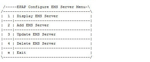
Display EMS Server
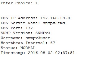
Configure EMS Server Menu option 1 displays all configured EMS servers. For PROV/Non PROV EPAP, the display operation displays the values of the fields shown in Figure 5-49. For PDB_ONLY EPAP, all fields except the StatusB field are displayed:
Figure 5-49 Display EMS Configuration for PROV/Non-PROV Server
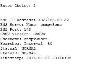
Figure 5-50 Display EMS Configuration for PDBonly EPAP
Add EMS Server
Configuration EMS Server Menu option 2 allows the addition of EMS servers:
- The user is allowed to configure IPv4 only remote system address
- The user is allowed to configure IPv6 only remote system address
- On dual stack - the user is allowed to configure IPv4 or IPv6 remote system address
- EMS IP Address
- IP address of EMS to receive traps
- EMS Server Name
- A logical name for the EMS
- EMS Port
- Destination UDP port
- EMS Community
- SNMP community contained in traps
- Heartbeat Interval [60]
- Number of seconds between heartbeat traps (system alive message); the default is 60 seconds if not specified
Figure 5-51 and Figure 5-52 display examples of adding IPv4 SNMPv2c EMS servers:
Note:
IPv6 Configuration, menu option 2, follows the same procedures as IPv4 for adding EMS servers.Figure 5-51 Add IPv4 SNMPv2c EMS When Global Is Set to Both for PROV/Non-PROV EPAP
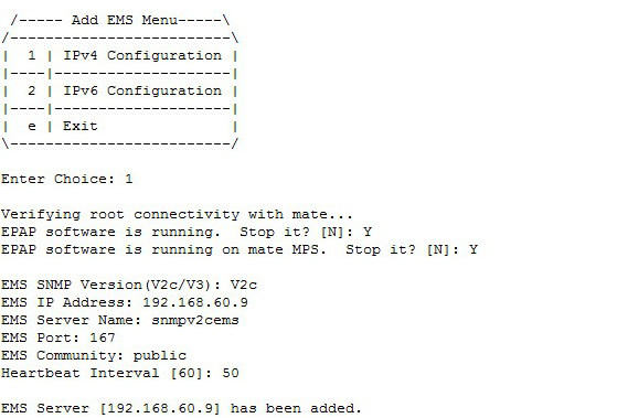
Figure 5-52 Add IPv4 SNMPv2c EMS When Global Mode Is Set to Both for PDBOnly EPAP

and display examples of adding IPv4 SNMPv3 EMS servers:
Figure 5-53 Add IPv4 SNMPv3 EMS When Global Mode Is Set to Both for PROV/Non-PROV EPAP
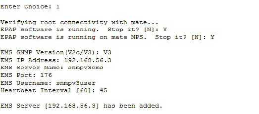
Figure 5-54 Add IPv4 SNMPv3 EMS When Global Mode Is Set to Both for PDBOnly EPAP

Update EMS Server
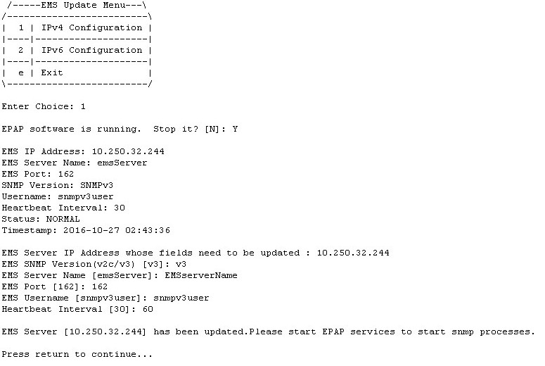
Configure EMS Server Menu option 3 allows the update of the EMS Server Name, EMS Port, EMS Community, and Heartbeat Interval fields for an EMS server IP address entered by the user, as displayed in .
Figure 5-55 Update EMS Configuration for PROV/Non-PROV EPAP When Global Mode Is SNMPv3
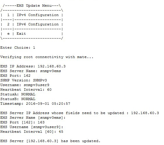
Figure 5-56 Update EMS Configuration for PDBOnly EPAP When Global Mode Is Both
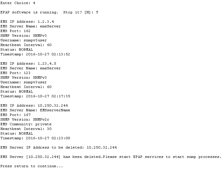
Delete EMS Server
Configure EMS Server Menu option 4 allows the deletion of the EMS server, as displayed in.
Figure 5-57 Delete EMS Configuration for PROV/Non-PROV
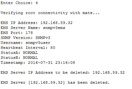
Figure 5-58 Delete EMS Configuration for PDBonly EPAP
Note:
- Name is the logic name for the EMS server with a valid length of 5 to 20 characters; Name is mandatory for both v3 and v2c configuration.
- Name must contain only alphanumeric characters (underscore is allowed) and is case insensitive when being configured.
- IP must be non-empty and unique. Both IPv4 and IPv6 EMS are supported.
- Port must be a valid value between range 1 to 65535, excluding the pre-defined ports.
- HeartBeat must be non-empty and in between a valid range of 0, 5 - 7200 for v3 configuration.
- Community String length cannot exceed 127 characters.
- Only alphanumeric characters, hyphen and underscore are allowed in Community.
- If Global Mode is set to SNMPv2c, the Community field is mandatory and the User field will not be displayed.
- If Global Mode is set to SNMPv3, the Community field will not be displayed and the User field is mandatory.
- User must be spelled in the exact case as it is configured in the User menu when being configured; If Global Mode is set to Both, either v2c or v3 "SNMP Version" will be selected. Community and User are mutually exclusive.
5.3.9.2 Autonomous Events Trap Forwarding
The EPAP SNMP agent forwards all autonomous events generated at the EPAP in the form of SNMP v2c traps to EMS(s) configured for SNMPv2c, or SNMPv3 traps to those configured for SNMPv3. One thread runs per EMS, which maintains its own head and tail to send the alarms to the SNMPv2c configured EMS or the SNMPv3 configured EMS. Trap forwarding from the EPAP to the SNMPv3 based EMS will remain the same, as in the case of SNMPv2c based EMS(s), except that the trap PDU will carry additional information related to USM entry for the EMS.
5.3.9.3 Connectivity Between EPAP and EMS
EPAP listens at the SNMP agent standard port "161" for SET/GET Message. On receiving GET/SET message, EPAP sends a response for the same at a configured destination port for EMS. EPAP sends SNMPv2c/SNMPv3 traps to the EMS at some port, which is configured by the user for that EMS server with the help of the epapconfig utility. A maximum of 5 EMSs can be connected to an EPAP.
5.3.9.4 Resynchronization
The resynchronization process is supported for both SNMPv2c and SNMPv3 EMS servers.
If any EMS (either SNMPv2c or SNMPv3) sends a SET request to EPAP (that sets object value of resyncVar to 1), then only that EMS will be resynchronized with EPAP. Incase all EMS(s) send a SET request to the EPAP, then resynchronization takes place for every EMS independently.
5.3.10 Configure Alarm Feed
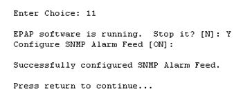
The Configure Alarm Feed option 11 allows the user to configure the Eagle Alarm Feed and SNMP Alarm Feed parameters. For PROV/Non PROV EPAP (see Figure 5-59), the EPAP software is stopped in both the EPAP A and EPAP B servers before configuring the alarm feeds.
Figure 5-59 Alarm Feed Configuration Menu for PROV/Non PROV EPAP

As shown in Figure 5-60, the Eagle Alarm Feed parameter is not configurable for PDB_ONLY EPAP. The EPAP software is stopped in the EPAP A server before configuring the alarm feed.
Figure 5-60 Alarm Feed Configuration Menu for PDB_ONLY EPAP
5.3.11 Configure Query Server
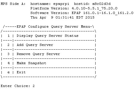
The Configure Query Server option 12 allows the user to configure the query server on EPAP, as shown in Figure 5-61, using either IPv4 or IPv6 addresses.
- The user is allowed to configure IPv4 only remote system address
- The user is allowed to configure IPv6 only remote system address
- On dual stack - the user is allowed to configure IPv4 or IPv6 remote system address
If no query server is configured, the MySQL binlogs are purged when the free disk space usage is more than the value set for epap_binlogs_threshold. The default value for epap_binlogs_threshold is 80%.
Note:
All Query Server related logs will be logged in the queryServer.log file@ /usr/TKLC/epap/logs. This logging includes configuration via the epapconfig menu, connectivity status of the Query Server, and alarms related to the Query Server on EPAP.
The following options are available in the epapconfig utility under the "Configure Query Server" tab:
- Display Query Server Status
- Add Query Server
- Remove Query Server
- Make Snapshot
Figure 5-61 Configure Query Server
Display Query Server Status
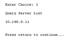
The Display Query Server Status option 1 displays the query server configured at the EPAP side, as shown in Figure 5-62.
Figure 5-62 Display Query Server Status
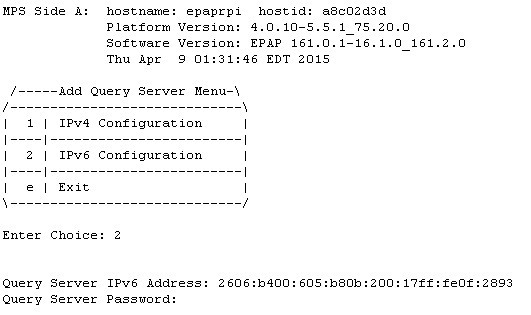
Add Query Server
The Add Query Server option 2 adds a query server at EPAP. As shown in Figure 5-63, the following parameters are configurable for a query server:
- IP address of the query server
- Password needed for replication user
Figure 5-63 Add Query Server
Remove Query Server
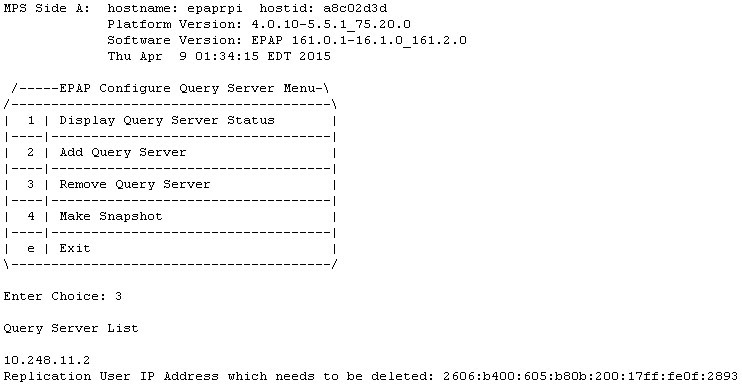
The Remove Query Server option 3 removes the query server configured at EPAP, as shown in Figure 5-64.
Figure 5-64 Remove Query Server
Make Snapshot
The Make Snapshort option 4 creates a snapshot of the EPAP PDB, as shown in Figure 5-65.
Figure 5-65 Make Snapshot

5.3.12 Configure Query Server Alarm Feed
The Configure Query Server Alarm Feed option 13 allows the user to turn on or turn off the Query Server Alarm Feed, as shown in Figure 5-66.
Figure 5-66 Configure Query Server Alarm Feed

When the Query Server Alarm Feed is set to ON, the EPAP QS Replication Issue and EPAP QS Lagging behind alarms can be raised in the system according to their alarm condition.
5.3.13 Configure SNMP Agent Community
The Configure SNMP Agent Community option 14 allows the user to configure the SNMP Read and Write Communities in the snmpd.conf file, as shown in Figure 5-67 and Figure 5-68. The default strings for the Read and Write communities in the snmpd.conf file are epapRdSnmp and epapWrSnmp.
Figure 5-67 Configure SNMP Agent Community Menu for PROV/Non PROV EPAP

Figure 5-68 Configure SNMP Agent Community Menu for PDB_ONLY EPAP

5.3.14 Configure Mate Disaster Recovery
Mate Disaster Recovery, menu option 15, performs disaster recovery on Mixed/Non-prov EPAP. Choosing this option allows for the entire disaster recovery process to be an authenticated procedure. Instead of re-installing the EPAP on both servers and redoing the configuration steps, the EPAP user is able to IPM only the bad server, install EPAP on it, and perform disaster recovery from the mate.
Note:
- This menu option is not supported on PDBonly setup.
- The menu option 15 does not work if VIP is configured on the server. To use this menu option remove the VIP configuration.
Figure 5-69 EPAP Configuration Menu on Server A
/-------EPAP Configuration Menu--------\
/----------------------------------------\
|  1 | Display Configuration             |
|----|-----------------------------------|
|  2 | Configure Network Interfaces Menu |
|----|-----------------------------------|
|  3 | Set Time Zone                     |
|----|-----------------------------------|
|  4 | Exchange Secure Shell Keys        |
|----|-----------------------------------|
|  5 | Change Password                   |
|----|-----------------------------------|
|  6 | Platform Menu                     |
|----|-----------------------------------|
|  7 | Configure NTP Server              |
|----|-----------------------------------|
|  8 | PDB Configuration Menu            |
|----|-----------------------------------|
|  9 | Security                          |
|----|-----------------------------------|
| 10 | SNMP Configuration                |
|----|-----------------------------------|
| 11 | Configure Alarm Feed              |
|----|-----------------------------------|
| 12 | Configure Query Server            |
|----|-----------------------------------|
| 13 | Configure Query Server Alarm Feed |
|----|-----------------------------------|
| 14 | Configure SNMP Agent Community    |
|----|-----------------------------------|
| 15 | Mate Disaster Recovery            |
|----|-----------------------------------|
|  e | Exit                              |
\----------------------------------------/
Enter Choice: 15
Figure 5-70 EPAP Configuration Menu on Server B
/-------EPAP Configuration Menu--------\
/----------------------------------------\
|  1 | Display Configuration             |
|----|-----------------------------------|
|  2 | Configure Network Interfaces Menu |
|----|-----------------------------------|
|  3 | Set Time Zone                     |
|----|-----------------------------------|
|  4 | Exchange Secure Shell Keys        |
|----|-----------------------------------|
|  5 | Change Password                   |
|----|-----------------------------------|
|  6 | Platform Menu                     |
|----|-----------------------------------|
|  7 | Configure NTP Server              |
|----|-----------------------------------|
|  8 | Security                          |
|----|-----------------------------------|
|  9 | SNMP Configuration                |
|----|-----------------------------------|
| 10 | Configure Alarm Feed              |
|----|-----------------------------------|
| 11 | Configure SNMP Agent Community    |
|----|-----------------------------------|
| 12 | Mate Disaster Recovery            |
|----|-----------------------------------|
|  e | Exit                              |
\----------------------------------------/
Enter Choice: 12
Note:
Once the user initiates Disaster Recovery, all the services are stopped on EPAP.Enter Choice: 12
WARNING: Are you sure you want to run Disaster Recovery on Mate? [N]: Y
Exchanging Keys with Mate...
Password of epapdev:
Could not get authorized keys file from remote (mate).
Maybe it does not exist. Continuing...
ssh is working correctly.
Password of root:
Could not get authorized keys file from remote (mate).
Maybe it does not exist. Continuing...
ssh is working correctly.
Password of admusr:
Could not get authorized keys file from remote (mate).
Maybe it does not exist. Continuing...
ssh is working correctly.
Password of root:
ssh is working correctly.After completion, the user must reconfigure the cron jobs (autobackup, PDB/RTDB) that were previously set. This information will be lost during Disaster Recovery.
If Server A goes down on a mixed setup and the Query Server was configured before Disaster Recovery, the user must reconfigure the Query Server as well, as this information will be lost along with the PDB database.
Note:
If disaster recovery is performed on a server having a backup-prov IP, the syscheck may retain the backup-prov IP and throw the error “Could not ping IPv4/IPv6 host mate-prov-bkup”. To prevent this error, remove the configured backup-prov IP and reconfigure it with the same backup-prov IP after completing the disaster recovery procedure. This removes the default IP from /etc/hosts and clears the syscheck alarm.
5.3.15 DB Architecture Menu
The epapconfig menu supports a
DB
Architecture sub-menu, option
15, which allows the DB Architecture to be changed from
the default "Compact" to "eXtreme."
Figure 5-71 EPAP B Configuration Menu
/-----EPAP Configuration Menu----------\
/----------------------------------------\
|  1 | Display Configuration             |
|----|-----------------------------------|
|  2 | Configure Network Interfaces Menu |
|----|-----------------------------------|
|  3 | Set Time Zone                     |
|----|-----------------------------------|
|  4 | Exchange Secure Shell Keys        |
|----|-----------------------------------|
|  5 | Change Password                   |
|----|-----------------------------------|
|  6 | Platform Menu                     |
|----|-----------------------------------|
|  7 | Configure NTP Server              |
|----|-----------------------------------|
|  8 | PDB Configuration Menu            |
|----|-----------------------------------|
|  9 | Security                          |
|----|-----------------------------------|
| 10 | SNMP Configuration                |
|----|-----------------------------------|
| 11 | Configure Alarm Feed              |
|----|-----------------------------------|
| 12 | Configure Query Server            |
|----|-----------------------------------|
| 13 | Configure Query Server Alarm Feed |
|----|-----------------------------------|
| 14 | Configure SNMP Agent Community    |
|----|-----------------------------------|
| 15 | DB Architecture Menu              |
|----|-----------------------------------|
|  e | Exit                              |
\----------------------------------------/

Enter Choice:15
/-----DB Architecture Menu--------------\
/----------------------------------------\
|  1 | Display running DB Architecture   |
|----|-----------------------------------|
|  2 | Change DB Architecture to eXtreme |
|----|-----------------------------------|
|  e | Exit                              |
\----------------------------------------/
In the default "Compact" DB Architecture, the EPAP will run the version of RTDB and MAINT processes that are compatible with EAGLE 46.5 and 46.6.
Note:
The "PDB Capacity Menu" will not be displayed in the "Compact" DB Architecture.Changing the DB Architecture from "Compact" to "eXtreme" requires the EPAP software to restart and run a new version of RTDB and MAINT process to support the capacity expansion. The connecting EAGLE must upgrade to the new release with SLIC cards running 64-bit SCCP applications in order to support this DB schema before the change. SM8G-B cards are not supported in the "eXtreme" DB architecture.
5.4 EPAP Configuration Procedure
Initialization and configuration are provided through a text-based user interface (UI) described in this chapter. The user accesses the text-based configuration procedure using the product UI.
The first time that user epapconfig logs into MPS A the system performs an auto-configuration on both MPS EPAP pairs. The sync network and main and backup DSM networks are initialized to their default values, described in Network Connections and defined in Application B Card Hardware and Installation Guide. Various internal configuration parameters are also set to their default values. The installer must perform initial configuration on MPS A on EAGLE A and MPS A on EAGLE B. The installer must also perform initial configuration on non-provisionable MPSs, if they are present.
See Standalone PDB EPAP for the procedure to configure Standalone PDB EPAPs.
5.4.1 Configuration Terms and Assumptions
-
The initial configuration steps assume that each MPS has previously undergone successful Initial Platform Manufacture (IPM).
-
The network path must be present and verified before the MPS servers are ready for EPAP configuration.
-
Initial configuration can be implemented on only the MPS A side of EAGLE A and MPS A side of EAGLE B. Attempting to perform initial configuration on MPS B of EAGLE A is not allowed, and the
epapconfiguser will be notified. The attempted configuration will be aborted with no impact on either MPS A or B.After the initial configuration of MPS A on EAGLE A and MPS A on EAGLE B, both EPAPs should be operational unless the system failed to successfully initialize during reboot or the configured values for the Sync and/or DSM networks conflict with other equipment in the network. Tekelec recommends that you do not change the default network values.
-
The provisioning values displayed for the following initialization and configuration steps are example values only.
-
Default values can be accepted just by pressing the Return key at the prompt; default values are shown enclosed in brackets [ ].
-
It is the customer's decision about the timing and frequency of performing a back-up of his databases. Of course, databases should be backed up when they are initially populated with data; however, the priority that the customer assigns to data and time lost in restoring it will dictate the frequency of database back-up.
-
Adding an NTP server is optional. Additionally, only one NTP server is needed to provide time synchronization for all the MPS servers on both EAGLE pairs. Up to 3 external servers are supported.
-
The EPAP terms 'local' and 'remote' are relative with respect to the EPAP configuration software. In other words, if the installer is running the configuration software on the physical MPS (that is, the MPS that the installer is physically on-site and has his terminal connected to), the configuration software refers to that MPS as 'local'. However if the installer connects through the network into the MPS A on EAGLE B, the configuration software executing at EAGLE B sees itself as 'local', referring to MPS that the installer is physically connected to as the 'remote'.
Remember that the 'local' MPS is whichever MPS A that the configuration software is being executed on, regardless of where the user is physically located.
The MPS of EAGLE A is the first MPS to which the installer physically connects and on which initial configuration of the EPAPs is always begun.
To avoid confusion of these relative terms, the MPS A on EAGLE A is considered to be the on-site MPS to which the installer has the physical connection. This document refers to the MPS to which the installer does not have the physical connection as MPS A on EAGLE B.
5.4.2 Configuration Symbols
During the Configuration Procedure, the installer will initialize and configure the MPSs to perform various functions. Special instructions are required occasionally for an MPS on EAGLE A, an MPS on EAGLE B, or a non-provisionable MPS. To assist the installer, this manual uses these notations to indicate individual instructions to be performed for those specific MPSs.
Table 5-8 Configuration Notations
|
Notation |
Notation Description |
|
A: MPS on EAGLE A: |
This notation indicates installation instructions to be performed specifically for the MPSs (MPS A and MPS B) on EAGLE A. |
|
B: MPS on EAGLE B: |
This notation indicates installation instructions to be performed specifically for the MPSs (MPS A and MPS B) on EAGLE B. |
|
N: Non-Provisionable MPS: |
This notation indicates installation instructions to be performed specifically for any non-provisionable MPSs. |
5.4.3 Initial Setup and Connecting to MPSs
Installation personnel may choose to employ various methods for connecting to an MPS. The EPAP software requires that an MPS be configured from side A. Refer to Application B Card Hardware and Installation Guide for the correct installation procedure.
5.4.4 Procedure for Configuring EPAPs
Perform the configuration procedure by following these steps in the text-based user interface. After you have connected to an MPS as described in Initial Setup and Connecting to MPSs, perform this procedure to configure the EPAPs in your network.
Note:
Initial configuration cannot be performed through the GUI because the IP addresses required for browser connectivity are not defined until the initial configuration using the text-based UI is completed.Using the set up and connection described previously,
connect to an MPS to perform configuration. In a typical installation, connect
directly to the MPS at EAGLE A to configure it, then use
ssh to connect to the MPS at EAGLE B
and configure it.
After connecting to the MPS on EAGLE A, you are prompted to log in.
5.4.5 Procedure for turning on EIRBLK
EIRBLK Expansion is a configurable feature that needs to be turned ON to provision more than 50,000 EIR Blocks. The PDBA limits EIR Block entries under 50,000 if the EIR_BLK_EXPANSION_200K feature is OFF.
5.4.6 Procedure for turning on DNBLK
DNBLK Expansion is a configurable feature that needs to be turned ON to provision more than 100,000 EIR Blocks. The PDBA limits EIR Block entries under 100,000 if the DN_BLK_EXPANSION_400K feature is OFF.
5.4.7 Turning on the 240M DN and 240M IMSIs via Split Database Feature
The 240M DN and 240M IMSIs via Split Database (EPAP_DATA_SPLIT) feature must be turned on to support the expanded RTDB capacity. This feature must be turned on the EAGLE side.
See "Activating the EPAP Data Split and Dual ExAP Configuration Features" in Database Administration - GTT User's Guide for EAGLE for configuration.
Supported DB Capacity
As of Release 16.3, flexible provisioning of DN/IMSI/IMEI data with the available disk size and SM memory size is supported, allowing the maximum number of data provisioned to be irrespective of the type of data. The following DB capacities are supported:
Note:
The E5-SM8G-B card does NOT support the increased (480 M DN + 480 M IMSI + 600Mn IMEI) capacities - it supports only the existing capacities for EPAP 16.2/16.1, which is 240M DN + 240M IMSI + 48M IMEI.Table 5-9 Supported DB Capacity
| EPAP TYPE/Disk Size | EPAP Operation Mode | SM card type with "EPAP Data Split" feature status | DB Capacity and Configuration | DB Capacity limiting factor; Minimal memory size required to be available on SM (in Bytes) |
|---|---|---|---|---|
| E5APPB-02/480GB | Standalone PDB; Mixed EPAP | E5-SM8G-B (epap240M ON) with "EPAP Data Split" feature OFF | Total Max DB:
288M DN/IMSI/IMEI Current capacity NOT configurable in the Configuration menu. |
E5-SM8G-B memory size |
| E5APPB-02/480GB | Standalone PDB; Mixed EPAP | E5-SM8G-B (epap240M ON) with "EPAP Data Split" feature ON | Total Max DB 528M:
DN - 240M IMSI - 240M IMEI - 48M Current capacity NOT configurable in the Configuration menu. |
E5-SM8G-B memory size |
| E5APPB-02/480GB | Standalone PDB | SLIC (EPAPX ON) with "EPAP Data Split" feature OFF | Total Max DB:
480M DN/IMSI/IMEI |
None;
11,617,463,954 |
| E5APPB-02/480GB | Standalone PDB | SLIC (EPAPX ON) with "EPAP Data Split" feature ON | Total Max DB 900M:
DN - 420M (each DN is provisioned with all possible fields) IMSI/IMEI - 480M |
E5APPB-02 Disk size;
10,148,933,426 |
| E5APPB-02/480GB | Standalone PDB | SLIC (EPAPX ON) with "EPAP Data Split" feature ON | Total Max DB 1080M:
DN - 480M (Standalone DNs associated with a Network Entity or a portability type; other fields such as asd, nsdn, cgbl, cdbl, should not be used) IMSI/IMEI - 600M |
E5APPB-02 Disk size;
12,631,033,322 |
| E5APPB-02/480GB | Standalone PDB | SLIC (EPAPX ON) with "EPAP Data Split" feature OFF or ON | Max DNBLK 400K; or
800K; or 1600K |
None.
Default Max DNBLK is 400K |
| E5APPB-02/480GB | Standalone PDB | SLIC (EPAPX ON) with "EPAP Data Split" feature OFF or ON | Max EIRBLK 100K; or
200K; or 800K |
None.
Default Max EIRBLK is 100K |
Note:
With the "EPAP Data Split" feature ON, the data will be loaded only to EAGLE SM cards configured to be data=DN/IMSI.The enhancement also supports DN Block capacity expansion from 200K to 400K, and optionally a max of 800K or 1600K DN Block is supported.
EIR Block capacity is optionally increased from 100K to configurable 200K or 800K.
