Monitor the Enhanced PDU (HTML Interface)
Using the metering unit's HTML interface, you can monitor how much power, energy, and current the equipment attached to the PDU uses, as well as the voltage level powering the equipment. The reported voltage for 3ph PDUs is L-N for HV PDUs and L-G for LV PDUs. The reported voltage for 1ph PDUs is L-N for HV PDUs and L-L for LV PDUs. You can see how the current and voltage readings relate to the threshold parameters you set in Set Threshold Parameter Values (Enhanced PDU).
-
Access the PDU metering unit from a system on the network.
See Access a Metering Unit on the Network (Enhanced PDU). After accessing the PDU, the Metering Overview page displays.
-
View the Metering Overview page.
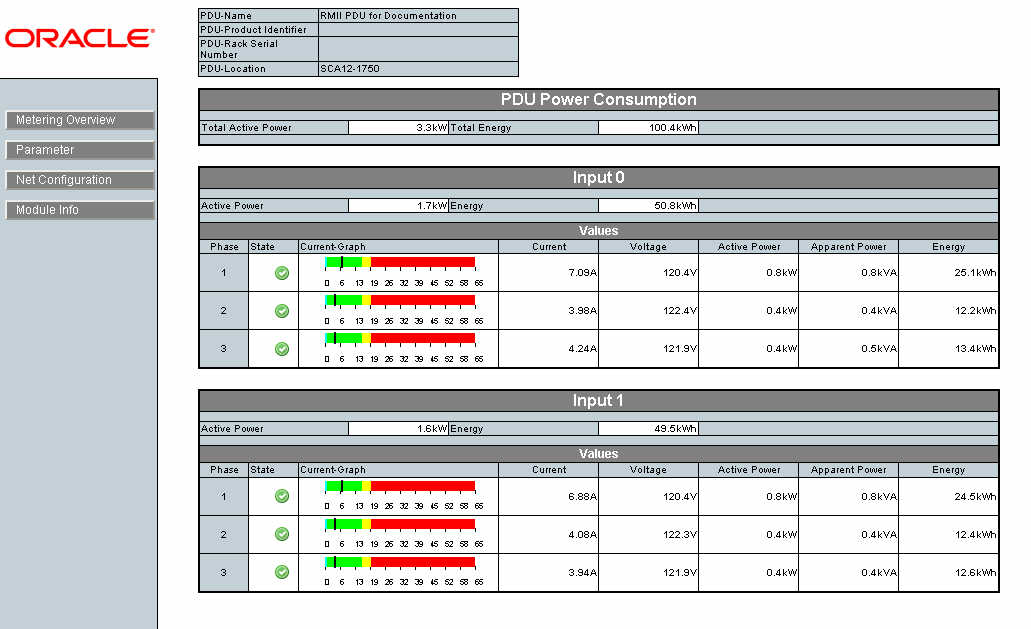
The following figure shows an example Metering Overview page for a 24kVA PDU, which has two inputs with three phases each. See Understanding the Relationship Between Inputs and Outlet Groups for a description of PDU inputs.

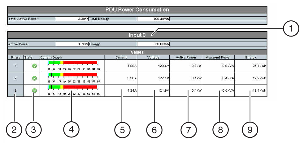
The following figure displays the details of the current measurement of an example single PDU input.
 No.Description12Phase number3State45Number of amps of current being used per phase6Voltage level applied per phase
The reported voltage for 3ph PDUs is L-N for HV PDUs and L-G for LV PDUs. The reported voltage for 1ph PDUs is L-N for HV PDUs and L-L for LV PDUs.
7Amount of active power being used per phase8Amount of apparent power being used per phase9Energy level being used per phaseThe black vertical bar indicates the current used by the attached equipment. The color behind the line is determined by the threshold parameter values. If you set voltage threshold parameter values, the background of the voltage color indicates the state of the voltage powering the equipment. For more information on threshold limits, see Set Threshold Parameter Values (Enhanced PDU).
Note - The Enhanced PDU supports both, 10/100 Full Duplex and 10/100 Half Duplex as well as auto-negotiation as defined in IEEE802.3u. If the switch port supports auto-negotiation the Enhanced PDU will configure itself to the fastest speed supported by the switch. If a specific mode of operation is needed the switch port needs to be configured to the specific mode of operation.ColorValueDescriptionBlueGreenMeasured current is between the Info and Warning thresholds.Attached equipment is using the expected amount of current.YellowMeasured current is above the Warning threshold, but below the Alarm threshold.Attached equipment is using more current than expected.RedAttached equipment is using a critical amount of current and requires immediate attention.Flashing bar with red textThe equipment attached to one phase is using more current than the other phases on the input. The PDU and attached equipment require immediate attention.
Caution - If the PDU is out of balance, the PDU and the attached equipment might heat up and cause serious damage to the equipment, PDU, and the rack. Power off the equipment and the PDU immediately.
If you set voltage thresholds parameter values, the background of the voltage color indicates the state of the voltage powering the equipment. See the following table for a description of these colors.
ColorValueDescriptionGreenMeasured Voltage is above Warning threshold.Attached equipment is operating with an expected voltage level.YellowMeasured Voltage is between Warning and Alarm threshold.Attached equipment is operating at an allowable voltage level.RedAttached equipment might not operate as expected.
Caution - If the PDU input voltage is below the Alarm level, the attached equipment (and PDU) might be damaged. Power off the equipment and PDU immediately.