Go to main content
oracle home
Oracle
®
Exadata X8-2 Database Server Service Manual
Exit Print View
Search Term
» ...
Documentation Home
»
Documentation Library
»
Oracle
®
Exadata X8-2 Database ...
»
Servicing PCIe Cards
»
Install a PCIe Card in PCIe Slot 3
Updated: July 2020
Oracle
®
Exadata X8-2 Database Server Service Manual
Document Information
Using This Documentation
Product Documentation Library
Feedback
About the Oracle Exadata X8-2 Database Server
Product Description
Server Physical Specifications
Front and Back Panel Components
Front Panel Controls and Indicators
Back Panel Components and Cable Connections
About System Components
Illustrated Parts Breakdown
Replaceable Components
Installation Procedure
Installation Procedure Overview
Troubleshooting and Diagnostics
Troubleshooting Server Component Hardware Faults
Troubleshooting Server Hardware Faults
Basic Troubleshooting Process
Related Information
Troubleshoot Hardware Faults Using the Oracle ILOM Web Interface
Troubleshooting and Diagnostic Information
Troubleshooting Using the Server Front and Back Panel Status Indicators
Related Information
Server Boot Process and Normal Operating State Indicators
Server System-Level Status Indicators
Server Fan Status Indicators
Storage Drive Status Indicators
Power Supply Status Indicators
Network Management Port Status Indicators
Ethernet Ports Status Indicators
Motherboard Status Indicators
Troubleshooting System Cooling Issues
Troubleshooting Power Issues
Managing Server Hardware Faults Through the Oracle ILOM Fault Management Shell
Troubleshooting With Diagnostic Tools
Diagnostic Tools
Diagnostic Tool Documentation
Attaching Devices to the Server
Attach Devices to the Server
Back Panel Connector Locations
Configuring Serial Port Sharing
Assign Serial Port Output Using the Oracle ILOM CLI
Assign Serial Port Output Using the Oracle ILOM Web Interface
Ethernet Port Boot Order and Device Naming
Ethernet Port Boot Order
Ethernet Port Device Naming
Back Panel Pinhole Switches
Getting Help
Contacting Support
Locating the Chassis Serial Number
Locating the Exadata Database Machine Rack Serial Numbers and JobID Label
Preparing for Service
Safety Precautions
Safety Symbols
Electrostatic Discharge Safety
FRU Key Identity Properties (KIP) Automated Update
Required Tools
Preparing the Server for Component Replacement
Powering Down the Server
Power Down the Server for Immediate Shutdown Using the On/Standby Button
Power Down the Server for Immediate Shutdown Using the Oracle ILOM CLI
Power Down the Server for Immediate Shutdown Using the Oracle ILOM Web Interface
Disconnect Cables From the Server
Extend the Server to the Maintenance Position
Remove the Server From the Rack
Take Antistatic Measures
Remove the Server Top Cover
Servicing Storage Drives
Storage Drives Hot-Plug Conditions
Storage Drive Locations and Numbering
Removing and Replacing a Storage Drive
Remove a Storage Drive
Install a Storage Drive
Servicing Fan Modules
Remove a Fan Module
Install a Fan Module
Servicing Power Supplies
Power Supply Overview
Remove a Power Supply
Install a Power Supply
Servicing the DIMMs
DIMM and Processor Physical Layout
DIMM Population Scenarios
DIMM Population Rules
DIMM Operating Speeds
Inconsistencies Between DIMM Fault Indicators and the BIOS Isolation of Failed DIMMs
Using the Server Fault Remind Button
Identify and Remove a DIMM
Install a DIMM
Servicing PCIe Risers
PCIe Riser Location and Differences
Remove a PCIe Riser From PCIe Slot 1 or 2
Install a PCIe Riser Into PCIe Slot 1 or 2
Remove the PCIe Riser From PCIe Slots 3 and 4
Install the PCIe Riser Into PCIe Slots 3 and 4
Servicing PCIe Cards
PCIe Slot Characteristics
Remove a PCIe Card From PCIe Slot 1 or 2
Install a PCIe Card in PCIe Slot 1 or 2
Remove a PCIe Card From PCIe Slot 3
Install a PCIe Card in PCIe Slot 3
Servicing the Battery
Remove the Battery
Install the Battery
Servicing Processors
Identify and Remove a Processor
Install a Processor
Servicing the Disk Backplane
Remove the Disk Backplane
Install the Disk Backplane
Servicing the Front LED Indicator Module
Remove the Front LED Indicator Module
Install the Front LED Indicator Module
Servicing the Temperature Sensor
Remove the Temperature Sensor
Install the Temperature Sensor
Servicing the Internal HBA Card and HBA Super Capacitor
Remove the Internal HBA Card and HBA Super Capacitor
Install the Internal HBA Card and HBA Super Capacitor
Servicing the Internal HBA Cables
Remove the Internal HBA Cables
Install the Internal HBA Cables
Servicing Other Cables
Remove the Power, FIM, Temperature Sensor, and Disk Backplane Data Cables
Install the Power, FIM, Temperature Sensor, and Disk Backplane Data Cables
Servicing the Motherboard Assembly
Remove the Motherboard
Install the Motherboard
Returning the Server to Operation
Server Filler Panel Requirements
Remove and Install Filler Panels
Install the Server Top Cover
Remove Antistatic Measures
Reinstall the Server Into the Rack
Return the Server to the Normal Rack Position
Reconnect Data Cables and Power Cords
Power On the Server
Identifying the Server Ports
Gigabit Ethernet Ports
RJ-45 10GbE Ports
SFP+ 10/25GbE Ports
Network Management Port
Serial Management Port
USB Ports
Setting Up BIOS Configuration Parameters
Manage the BIOS Configuration
Accessing the BIOS Setup Utility
BIOS Setup Utility Menus
BIOS Key Mappings
Access BIOS Setup Utility Menus
Navigate BIOS Setup Utility Menus
Using UEFI BIOS
Configuration Utilities for Add-In Cards
Configure and Manage BIOS Using Oracle ILOM
UEFI Secure Boot
Trusted Execution Technology
Common BIOS Setup Utility Tasks
Verify BIOS Factory Default Settings
Select a Temporary Boot Device
Configure TPM Support
Configure UEFI Driver Settings
Configure I/O Resource Allocation
Configure UEFI Secure Boot
Configure Trusted Execution Technology
Exit BIOS Setup Utility
BIOS Setup Utility Menu Options
BIOS Main Menu Selections
BIOS Advanced Menu Selections
BIOS Advanced Menu Serial Port Console Redirection Options
BIOS Advanced Menu Network Stack Options
BIOS Advanced Menu NVMe Configuration Options
BIOS Advanced Menu Primary Video Selection Option
BIOS Advanced Menu Trusted Computing 2.0 Options
BIOS Advanced Menu Disk Freeze Lock Settings Option
BIOS Advanced Menu PCH SATA Configuration Options
BIOS Advanced Menu Processor Configuration Options
BIOS Advanced Menu Memory Configuration Options
BIOS Advanced Menu CPU Power Management Configuration Options
BIOS Advanced Menu USB Ports Options
BIOS Advanced Menu Error Injection Settings Option
BIOS Advanced Menu T1s Auth Configuration Options
BIOS Advanced Menu RAM Disk Configuration Options
BIOS Advanced Menu iSCSI Configuration Options
BIOS Advanced Menu Intel Virtual RAID on CPU Options
BIOS Advanced Menu Gigabit Network Connection Options
BIOS Advanced Menu Oracle Dual Port 10Gb/25Gb SFP28 Ethernet Controller Options
BIOS Advanced Menu Driver Health Options
BIOS IO Menu Selections
BIOS IO Menu PCI Subsystem Settings Options
BIOS IO Menu IO Virtualization Options
BIOS IO Menu IOAT Configuration Options
BIOS IO Menu PCIE Hardware Slot Configuration Options
BIOS IO Menu Internal Devices Options
BIOS IO Menu Add-in Cards Options
BIOS Boot Menu Selections
BIOS Exit Menu Selections
Monitoring Components and Identifying SNMP Messages
Monitoring Component Health and Faults Using Oracle ILOM
Monitoring System Components
System Chassis Components
Cooling Unit Components
Disk Backplane Components
Memory Device Components
Power Unit Components
Processor Components
System Motherboard Components
System Firmware Components
Hard Disk Drive Components
Identifying SNMP Trap Messages
Environmental Events
Hard Disk Drive Events
Power Events
Fan Events
Memory Events
Entity Presence Events
Index
Index A
Index B
Index C
Index D
Index E
Index F
Index G
Index H
Index I
Index L
Index M
Index N
Index O
Index P
Index R
Index S
Index T
Index U
Index W
Language:
English
Install a PCIe Card in PCIe Slot 3
Retrieve the PCIe card and riser you want to install.
Locate the proper PCIe slot for the card you are replacing.
See
Illustrated Parts Breakdown
.
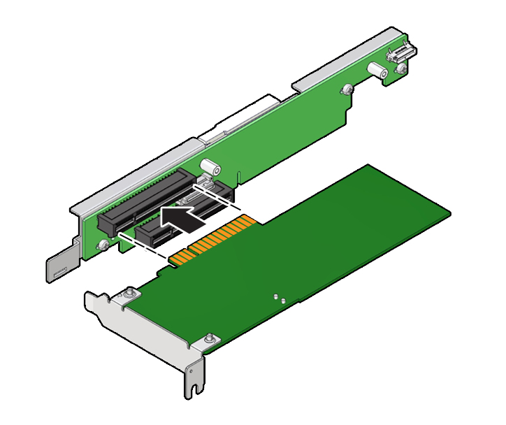
Insert the rear bracket that is attached to the PCIe card into the PCIe riser.
Hold the riser in one hand and use your other hand to carefully insert the PCIe card connector into the riser.
Install the PCIe riser.
See
Install the PCIe Riser Into PCIe Slots 3 and 4
.
Previous
Next