Release 14c (14.1.2.0.0)
Part Number F92121-01
Contents
Previous
Next
| Oracle Fusion Middleware Oracle E-Business Suite Adapter User's Guide Release 14c (14.1.2.0.0) Part Number F92121-01 | Contents | Previous | Next |
This chapter discusses some essential concepts for Oracle E-Business Suite Adapter. It provides basic understanding about how applications context, security, logging, and flexfields are used or supported as well as how errors and exceptions are handled. Detailed concepts described in this chapter are:
Applications context is required for invoking interfaces within Oracle E-Business Suite. Applications context is a combination of Username, Responsibility, Responsibility Application, and Security Group. These elements may be required for executing an interface successfully within Oracle E-Business Suite.
You can define multiple organizations and the relationships between them in a single installation of Oracle E-Business Suite. These organizations can be sets of books, business groups, legal entities, operating units, or inventory organizations.
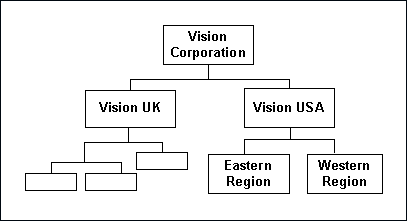
Multilevel organization hierarchies can be defined with a business group at the top of each hierarchy. When you define new organizations, they are automatically assigned to the business group associated with your current session. Each organization is part of a business group. The business group is usually the top box on an enterprise organization chart, as shown in the following diagram:
Business Group Hierarchy Diagram
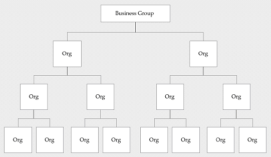
Example of a Multiple-Organization Setup
Using the accounting, distribution, and materials management functions in Oracle E-Business Suite, you define the relationships among inventory organizations, operating units, legal entities, and sets of books to create a multilevel company structure, as shown in the following diagram.
A Multiple-Organization Transaction Diagram
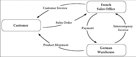
Consider two different organizations in your company: One is a French sales office and the other is a German warehouse. There is a sales order transaction with the customer, and this illustrates how the entire Order-to-Deliver process would work:
The customer places a sales order with the French sales office.
The German warehouse delivers the product shipment to the customer.
The German warehouse issues an inter-company invoice to the French sales office.
The French sales office makes the inter-company payment to the German warehouse.
The French sales office sends the customer invoice to the customer.
The customer makes payment to the French sales office.
The database architecture is the same for a multiple-organization and non-multiple-organization installation, and uses the standard install tools feature that automatically creates synonyms in the APPS schema for each base product table and defines these synonyms with the same name as the base product tables. For example, the PO Oracle schema has a table named PO_HEADERS_ALL and the APPS schema has a corresponding synonym of the same name, PO_HEADERS_ALL. The PO_HEADERS_ALL synonym can be used to access unpartitioned data.
Schema Synonyms
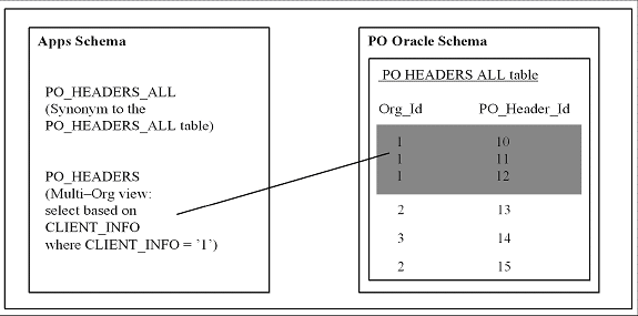
Multi-Organization Access Control (MOAC) Security by Operating Units
While setting up the system profile values, the username and responsibility are tied up with the organization or operating units.
System Profile Values Page
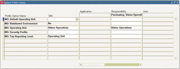
To have a secured way for users to allow access or report on data for the operating units they have access to, many of the interfaces within Oracle E-Business Suite make use of the MOAC security feature to determine the operating unit access privileges and derive the Organization ID based on relevant profile values. Oracle E-Business Suite Adapter can implicitly perform the requisite MOAC setup. If ORG_ID is passed, data access would be set to the passed Organization ID.
With MOAC, a system administrator can predefine the scope of access privileges as a security profile, and then use the profile option MO: Security Profile to associate the security profile with a responsibility. By using this approach, multiple operating units are associated with a security profile and that security profile is then assigned to a responsibility. Therefore, through the access control of security profiles, users can access data in multiple operating units without changing responsibility.
Security profiles are defined based on organization hierarchies. For example, a sales company consists of USA and UK operating units; the USA operating unit has Western Region Sales and East Region Sales. Sales managers are responsible for both USA and UK sales, supervisors are responsible for either USA or UK, and sales representatives are only responsible for their designated sales regions. The Sales organization hierarchy can be illustrated as follows:
Sales Organization Hierarchy
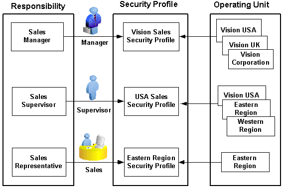
To secure sales data within the company, relevant operating units can be associated with predefined security profiles. For example, all sales data access privileges are grouped into the Vision Sales security profile. A USA Sales security profile is created for USA related data, and a regional security profile is created for designated regional data. The system administrator can associate these security profiles containing multiple operating units with users through appropriate responsibilities. Therefore, sales supervisors can easily access sales data in the Eastern or Western region without changing their responsibilities. The following diagram illustrates the relationship between security profiles, responsibilities, and operating units for this sales company:
Relationship Diagram Between Security Profiles, Responsibilities, and Operating Units
Responsibility Determines Operating Units
Because responsibilities are associated with security profiles that linked to operating units, your responsibility is the key in determining which operating units you will have the access privileges.
When integrating with Oracle E-Business Suite using PL/SQL APIs or Concurrent Programs, applications context is set based on the values passed for the header properties Username, Responsibility, Responsibility Application and Security Group.
Note: For backward compatibility reasons, no context related exceptions or errors would be thrown if none of the following header properties are passed - Responsibility Application, Security Group, and NLS Language.
MOAC setup is done based on the Responsibility Application to which the user belongs. If Organization ID is passed, the Organization access would be set to the passed Organization.
If the user needs the invocation of the interface to happen in a desired language, then the header property NLS Language can be passed. Default value for NLS Language would be the language specified in the user's preference in Oracle E-Business Suite.
To integrate business processes with Oracle E-Business Suite, it is essential to propagate these applications context values through a flexible mechanism, which is provided by Oracle E-Business Suite Adapter through the header properties.
The following topics are discussed in this section:
To effectively set applications context values required in a BPEL process or to populate mandatory header variables for XML Gateway inbound transactions to be completed successfully, Oracle E-Business Suite Adapter provides a flexible mechanism that allows each context value and header variable to be set and passed in the adapter user interface directly through the Invoke activity. This message normalization feature not only provides a flexible solution on header support, but also simplifies the design-time tasks without using an Assign activity to pass header values.
Setting Message Properties for Applications Context
The following header properties are used in setting applications context for PL/SQL and Concurrent Program interfaces:
jca.apps.Username
jca.apps.Responsibility
jca.apps.ORG_ID
jca.apps.RespApplication
jca.apps.SecurityGroup
Note: Existing header property jca.apps.Responsibility used in the earlier releases can now take Responsibility Key as well as Responsibility Name as input. If the header property jca.apps.NLSLanguage is set, and Responsibility Name is passed, the value passed for jca.apps.Responsibility is expected to be in the same language. However, Responsibility Key as well as all other header properties are language independent.
All these header properties would be used together to set the application context. Alternatively, passing just the Username and Responsibility would work as it did in the earlier releases.
In the case of a null or empty value, the default Username is SYSADMIN, the default Responsibility is System Administrator, the default Security Group Key is Standard, and the default NLS Language is US.
Setting Message Properties for XML Gateway Inbound Transactions
The following header message properties are used in setting XML Gateway information required for XML Gateway inbound/enqueue transactions:
jca.apps.ecx.TransactionType
jca.apps.ecx.TransactionSubtype
jca.apps.ecx.PartySiteId
jca.apps.ecx.MessageType
jca.apps.ecx.MessageStandard
jca.apps.ecx.DocumentNumber
jca.apps.ecx.ProtocolType
jca.apps.ecx.ProtocolAddress
jca.apps.ecx.Username
jca.apps.ecx.Password
jca.apps.ecx.Attribute1
jca.apps.ecx.Attribute2
jca.apps.ecx.Attribute3
jca.apps.ecx.Attribute4
jca.apps.ecx.Attribute5
jca.apps.ecx.Payload
Oracle E-Business Suite Adapter uses the following procedures to complete the design-time tasks to support message normalization:
This activity involves the following tasks:
Configure basic information in the General tab:
Configure an Invoke activity by linking the activity to the partner link you just created. This opens the General tab in the Edit Invoke dialog box with Partner Link and Operation information populated.
You can create an Input Variable and a Output Variable for the Invoke activity.
For detailed instructions, see Configure basic information in the General tab
Set the Header Message Properties in the Properties tab:
This is to set the necessary message properties for the following purposes:
To set XML Gateway header variables for an inbound transaction.
For example, locate XML Gateway header property jca.apps.ecx.TransactionType first and then enter a value (such as 'PO') for the selected property.
Edit Invoke: Properties Dialog
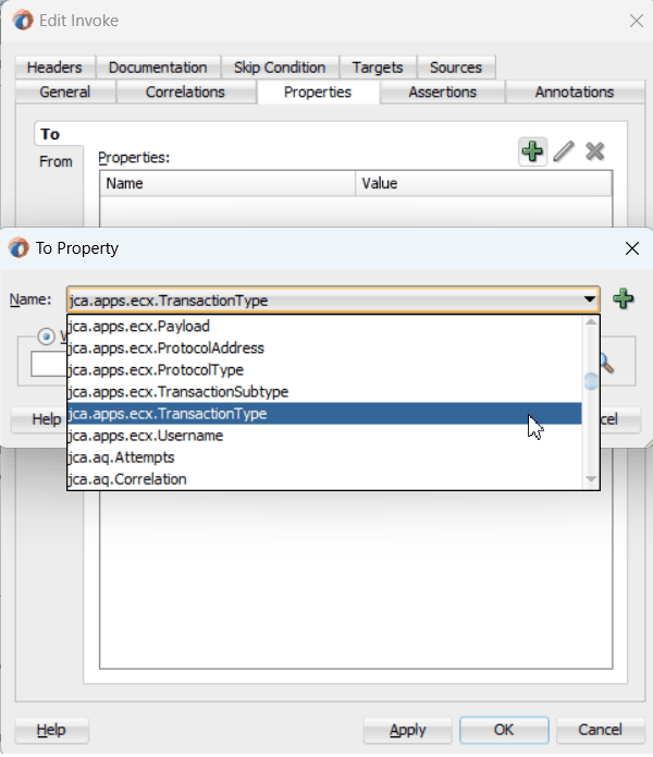
For detailed instructions, see Setting ECX Header Message Properties.
To set applications context for Oracle E-Business Suite to identify the application user, responsibility, and the user's associated organization information.
For example, locate the jca.apps.Username property from the property list and then enter 'OPERATIONS' as the property value.
For detailed instructions, see Setting the Header Properties for Applications Context.
Oracle E-Business Suite Adapter allows Organization ID to be passed as a header property which is available as jca.apps.ORG_ID within the Properties tab of an Invoke activity during the design time.
On Oracle E-Business Suite subsequent to Release 12.0, MOAC setup is automatically done using the call MO_GLOBAL.INIT(<Application Name>). Subsequently, if ORG_ID is passed, the call to MO_GLOBAL.set_policy_context('S', <ORG_ID>) would be made to set the Organization access to the specified ORG_ID.
Setting Header Message Properties
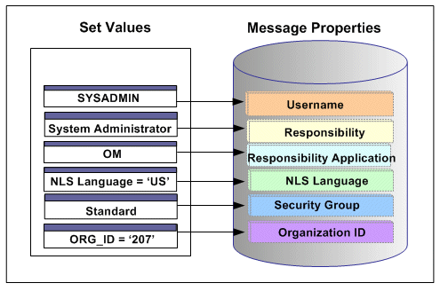
With the example described earlier in the Multiple Organization Setup section, when a change order is placed within the French sales office, a sales manager from the French office logs on to the system to update the order which invokes a PL/SQL API for that change. If the Organization ID contained in the header has been assigned with a property value, such as 207 for the French sales office, the Organization ID associated with the sales manager will be set to French sales office for the invocation of the API.
By leveraging the message normalization feature addressed earlier and the Multiple Language Support (MLS) feature from Oracle E-Business Suite, Oracle E-Business Suite Adapter provides a comprehensive language support mechanism that allows an appropriate language to be dynamically set at run time.
NLS Language Property Value Takes the Priority
When an application user retrieves data from the system for a transaction or receives error messages while executing APIs, the session language of data or error messages can be determined based on the following conditions:
The NLS Language value can be set by using the header property jca.apps.NLSLanguage. If a valid language value is passed (i.e. language is enabled in Oracle E-Business Suite instance), the session language is set to the corresponding language.
In case the NLS Language header property is not passed, Oracle E-Business Suite Adapter will use the default language of the user, based on the user preferences, to set the session language.
If the user's default language is not found or set, NLS Language (jca.apps.NLSLanguage) property value would be set to 'US' (American).
This mechanism allows an appropriate session language to be dynamically set at run time first based on the passed NLS Language property value, then the user's default language, and last determined by the default NLS Language property value 'US'.
For more information about how to set NLS Language property value by using jca.apps.NLSLanguage, see Support for Normalized Message Properties.
Determining a User's Default Language
To identify the default language used in the database session for data query and retrieval, Oracle E-Business Suite Adapter will first examine the ICX: Language profile value at all levels including user, responsibility, application, and site. If it is not set at any of those levels, Oracle E-Business Suite Adapter then takes NLS_LANGUAGE parameter from the database instance National Language Support (NLS) parameters. The NLS parameters initialized in the session are:
NLS_LANGUAGE
NLS_SORT
NLS_DATE_FORMAT
NLS_DATE_LANGUAGE
NLS_NUMERIC_CHARACTERS
NLS_TERRITORY
For example, when a user with a default language Japanese logs into the system and performs a transaction through the execution of an API that the user defined in the Partner link of the BPEL process, Oracle E-Business Suite Adapter will first examine if the NLS Language property value is passed. If it is passed with a valid language, then the session language will be set based on the passed value regardless of the default language. If the NLS Language property is not passed, Oracle E-Business Suite Adapter will set the session language to the preferred / default language of the user. In case that cannot be found, the language would be set to 'US' (American). The default language is set in the General Preferences page of Oracle E-Business Suite.
Note: The default language set in the General Preference page updates the ICX: Language profile option.
When the applications context is set, user preferences like date formats, time zone information, etc. would be taken care automatically.
Please refer to the Set Preferences section, Getting Started with Oracle E-Business Suite chapter, Oracle E-Business Suite User's Guide for the information on how to set the user preferences.
Oracle E-Business Suite Module Browser, formerly known as Oracle Applications Module Browser, is a key component of Oracle E-Business Suite Adapter. In addition to the interfaces that are made available through Oracle Integration Repository, Oracle E-Business Suite Adapter enables you to use business events and event groups, custom PL/SQL APIs, and custom XML Gateway maps, all of which you can explore using the Oracle E-Business Suite Module Browser.
Use the Module Browser to select the interface needed to define a partner link. It can be used in the following ways to locate desired interfaces:
Locating interfaces by Search
Locating interfaces by Browse
Searching Interfaces
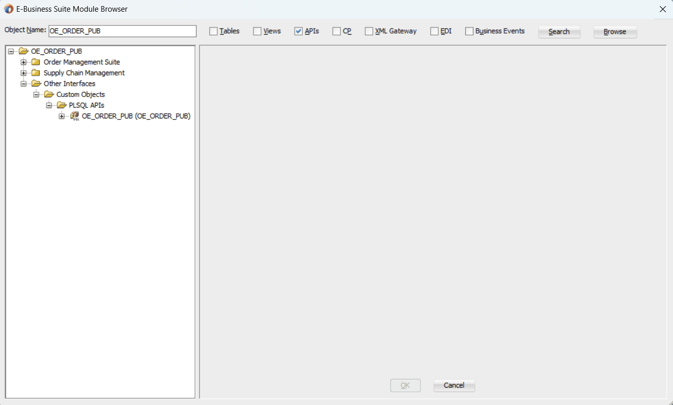
Enter desired interface name or partial values containing wildcard characters in the Object Name field and click Search to locate the desired interface in the Module Browser.
Oracle E-Business Suite Module Browser with Object Name Entered for a Search
Browsing Interfaces Through Tree Structure
The Module Browser combines interface data from Oracle Integration Repository along with additional interfaces supported by Oracle E-Business Suite Adapter.
Oracle E-Business Suite Module Browser with Interface Tree Expanded
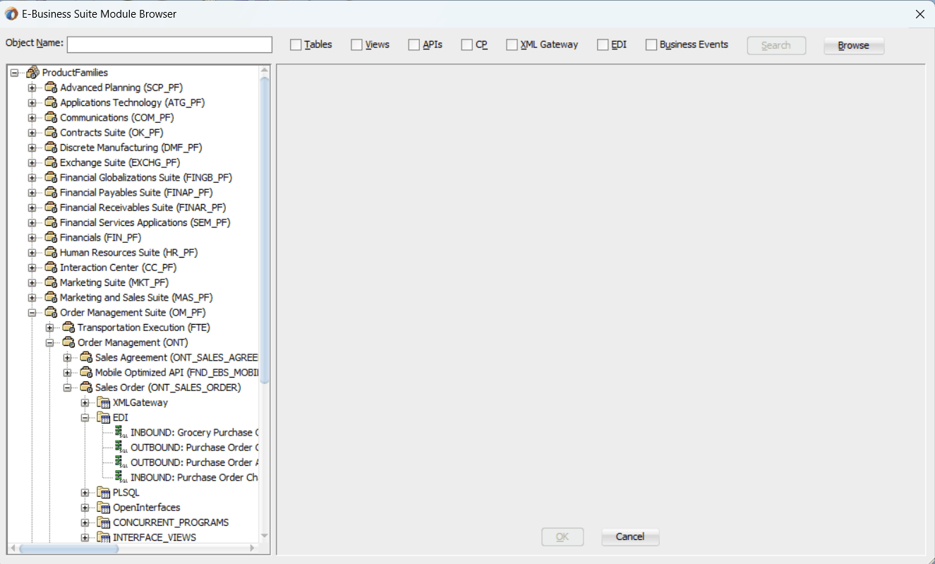
The supported interfaces are organized in a tree hierarchy as follows:
ProductFamilies
 |-[product_family]
 |  |-[product]
 |     |-[business_entity]
 |        |-XML Gateway ([n])
 |        |-EDI ([n])
 |        |-PLSQL ([n])
 |        |  |-[package_name]
 |        |-OpenInterfaces ([n])
 |           |-[OpenInterface_name]
 |              |-Tables ([n])
 |              |-Views ([n])
 |              |-ConcurrentPrograms ([n])
 |-Other Interfaces
    |-Business Events
       |-Inbound
       |-Outbound
          |-Groups
            |-[business event name]
    |-Custom Objects
       |-PLSQL APIs
       |  |-[package_name]
       |-XMLGateway Maps
          |-Inbound
          |-Outbound
       |-Concurrent Programs
			   |-[concurrent program name]
The items under Other Interfaces, as well as certain PL/SQL APIs and concurrent programs under the [product family] hierarchy, are available through Oracle E-Business Suite Adapter, but not through Oracle Integration Repository.
The number of interfaces indicated by [n] only appears in case of an Oracle E-Business Suite 11.5.10 instance is used. It will not be displayed if you are connecting to an Oracle E-Business Suite release 12 instance.
Browsing Interfaces by Product Family
The Oracle Integration Repository interface data populates the [product_family] sections, grouped according to the products and business entities to which they belong.
Oracle E-Business Suite Module Browser with Interfaces Displayed by Product Family

Browsing Business Events and Custom Interfaces Under 'Other Interfaces'
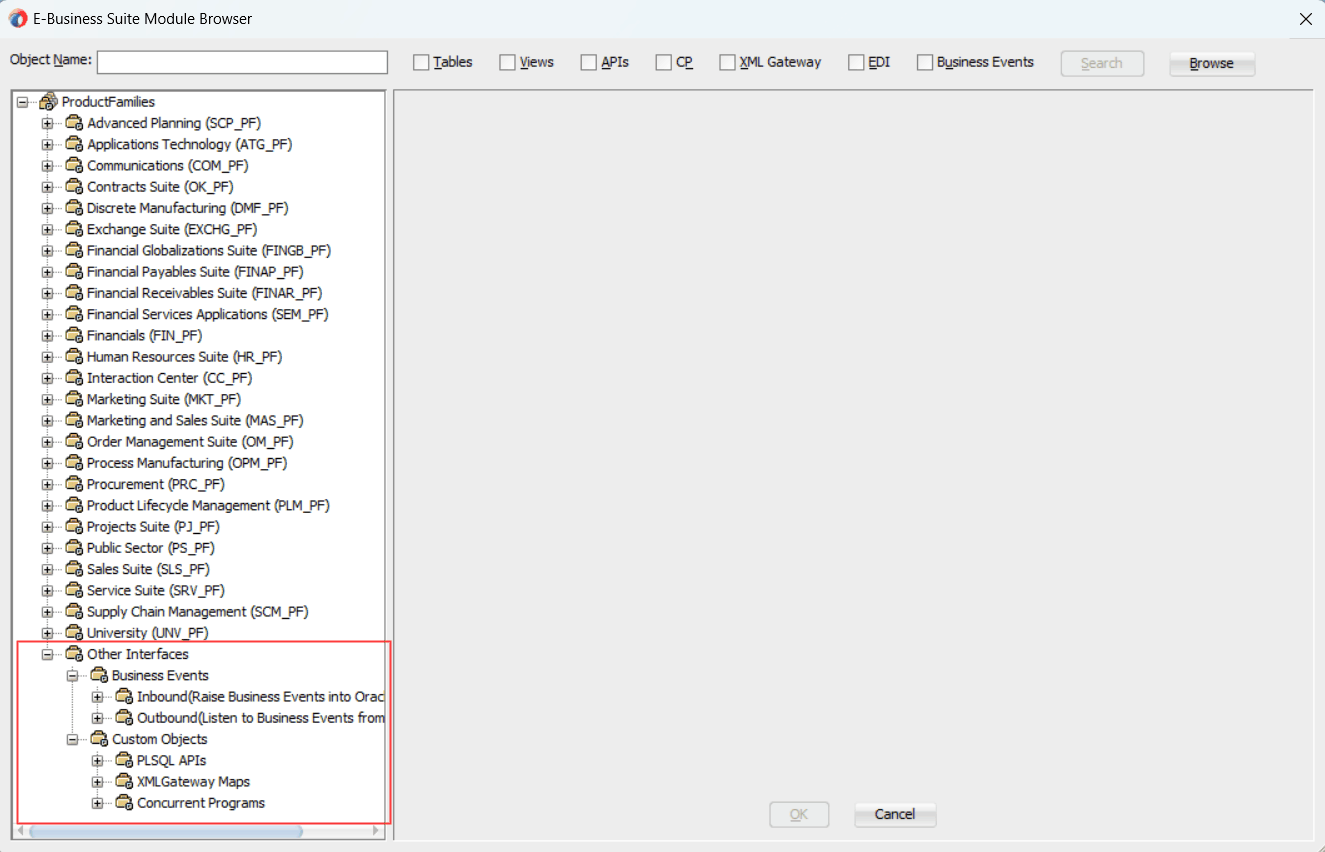
Business events and custom interfaces are displayed under the Other Interfaces note.
Oracle E-Business Suite Module Browser with Other Interfaces Highlighted
Business Events and Business Event Groups
Business events and business event groups appear under the Other Interfaces node from the Oracle E-Business Suite Module Browser.
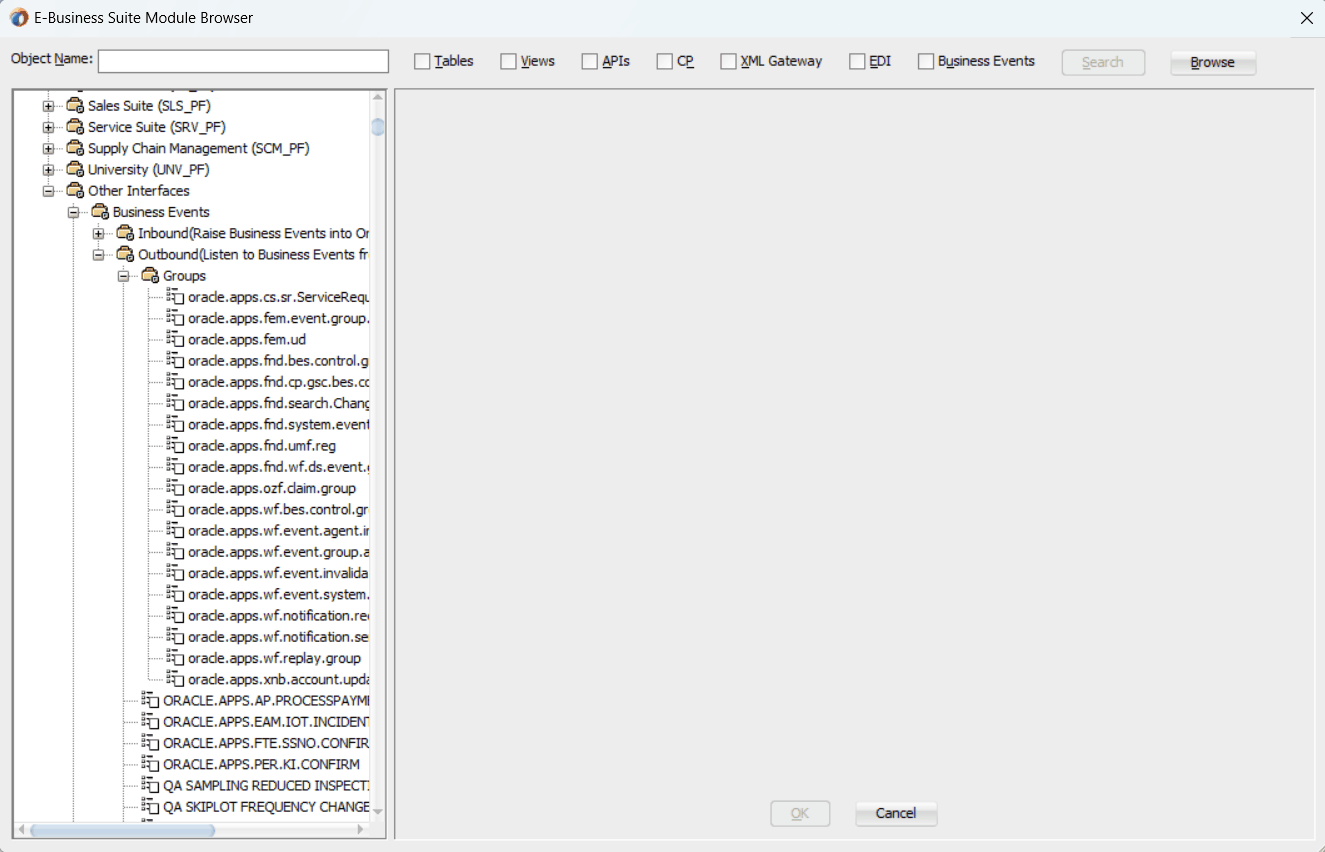
A business event group is a type of event containing a set of individual business events. Clicking the Other Interfaces > Business Events > Outbound > Groups node displays the business event groups.
Oracle E-Business Suite Module Browser with Interfaces Displayed Under Business Event Groups
Custom Interfaces
Custom interfaces are displayed under the Other Interfaces > Custom Objects node from the Oracle E-Business Suite Module Browser.
Oracle E-Business Suite Module Browser with Custom Interfaces Highlighted
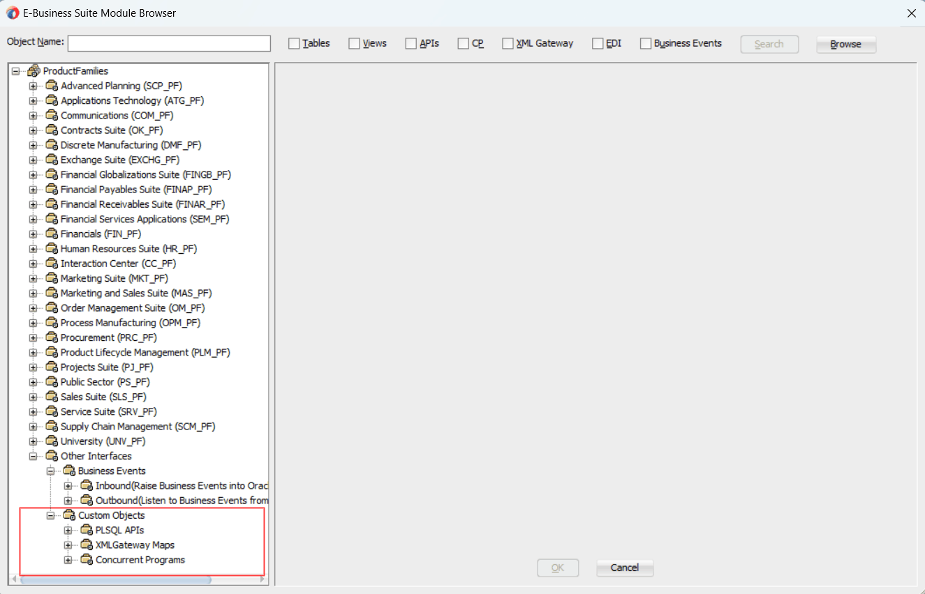
The supported custom interfaces are listed as follows:
Custom PL/SQL APIs
Custom PL/SQL APIs appear in two places:
Procedures within a package that's already exposed via Oracle Integration Repository appear under the package name within a product family hierarchy.
Procedures within a completely new package appear under the package name, under Other Interfaces > Custom Objects.
Custom XML Gateway Maps
Custom XML Gateway maps are categorized as either Inbound or Outbound. Select either one of the nodes to display custom XML Gateway maps.
Customized Concurrent Programs
Clicking the Concurrent Programs node under the Custom Objects node displays all the custom concurrent programs.
Security is the most critical feature that is designed to guard application content from unauthorized access. By leveraging Oracle User Management security mechanism, Oracle E-Business Suite Adapter provides a security feature which only allows users with authorized privileges to execute APIs that they are exposed through the BPEL process to update Oracle E-Business Suite. This protects application programming interfaces (APIs) from unauthorized access or execution without security checks.
Function Security with Role-Based Access Control (RBAC)
Function security is the basic access control in Oracle E-Business Suite. It restricts user access to individual menus and menu options within the system regardless of which application data in the row. Since APIs are stored procedures that enable you to insert and update data in Oracle E-Business Suite, when having the function security layer enforced on the access to an API, it actually implicitly restricts the data access to the Oracle E-Business Suite application.
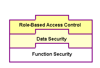
Building on function security, data security provides another layer of security control to model or enforce security authorizations of specific data records. In other words, data security further refines the security of accessing application records down to the data level.
To provide granular security control and allow only appropriate users with right privileges to execute APIs, Oracle E-Business Suite Adapter leverages Oracle User Management Role-Based Access Control security (RBAC) to reinforce the function security through user roles. Whether a user can access an API is determined by the roles granted to the user. This approach builds upon data security and function security, but it goes beyond both of them, as shown in the following diagram.
Function Security with Role-Based Access Control
To better understand how the security works for Oracle E-Business Suite Adapter, the following topics are included in this section:
Oracle E-Business Suite Adapter provides a way to handle access control for overloaded PL/SQL APIs. This feature works in conjunction with the grants created from the Integration Repository user interface, and it does not depend on any profile options.
Note: This security support would work with all interfaces which are available in the Integration Repository. For other interfaces, you need to enable the function security through the profile option mentioned in the section Function Security Support through Profile Option.
For this purpose, two new JCA properties are introduced:
DataSecurityCheck
IRepOverloadSeq
If a user wants the Function Security Authorization check to be performed, the following property information needs to be added in the WSDL file (XX_apps.jca):
<property name="DataSecurityCheck" value="yes"/>However, the other property IRepOverloadSeq is derived automatically by Oracle E-Business Suite Adapter at the design time during creation of the partner link. Based on these two properties, the function security check would be done for the username, which is passed as a header property.
Creating Security Grants through Integration Repository
This type of data security check for overloaded functions works in conjunction with security grants created through the Integration Repository user interface. This security grant can be performed in the Create Grant page for a given interface type to control the method at a very granular level.
An integration repository administrator can select one or more methods in a PL/SQL API and then authorize a user, user group, or all users to execute the selected method(s) by creating appropriate security grants.
Create Grants Page in Oracle Integration Repository
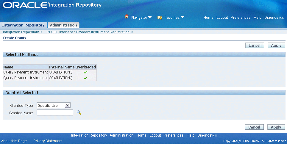
In the Integration Repository user interface, each overloaded function contained in an interface can be uniquely granted to a specific user, user group, or all users through the create grant feature. If you select more than one overloaded function in the Procedures and Functions region (or the Methods region), in the Create Grant page an Overloaded column appears in the selected methods table indicating more than one overloaded function is selected for the grant.
For more information on how to create security grants using the Integration Repository user interface, see Managing Security Grants, Administering Native Integration Interfaces and Services chapter, Oracle E-Business Suite Integrated SOA Gateway Implementation Guide for details.
Based on the function security with Role-Based Access Control (RBAC), security access control is defined through user roles and whether a user can access an API is determined by the roles granted to the user. A role can be configured to consolidate the responsibilities, permissions, permission sets, and function security policies that users require to perform a specific function. This simplifies mass updates of user permissions because changes can be done through roles which will inherit the new sets of permissions automatically. Based on the job functions, each role can be assigned a specific permission or permission set if needed. For example, a procurement organization may include 'Buyer', 'Purchasing Manager', and 'Purchasing Support' roles. The 'Purchasing Manager' role would include a permission set that contains all Purchase Order (PO) Creation, PO Change, and Contract PO related APIs allowing the manager role to perform a job function while the Buyer or Support role may not have the access privileges.
In Oracle E-Business Suite Adapter, all annotated APIs that reside in Oracle Integration Repository are registered on the FND_FORM_FUNCTIONS table so that the function security (FND_FORM_FUNCTIONS) can be applied. This allows the creation of a secured function for each API.
By leveraging the concept of permission sets, Oracle E-Business Suite Adapter allows related APIs to be grouped and sequenced under one permission set; each permission set can be associated with a function role and then assigned to users through security grants.
Enabling Function Security
Oracle E-Business Suite Adapter provides this security support as an optional feature. If you want all the login users to access and execute APIs without security checks, you can turn the security feature off using the "EBS Adapter for BPEL, Function Security Enabled" (EBS_ADAPTER_FUNCTION_SEC_ENABLED) profile option.
Note: Using "DataSecurityCheck" described in the earlier section for overloaded functions is the preferred way for interfaces listed in the Integration Repository because it is easy to create the security grants and doesn't depend on any profile options.
If it is set to 'Y', then the function security feature is enabled and all API calls for PL/SQL APIs, Oracle e-Commerce Gateway, and concurrent programs will be checked for user security before they are invoked.
If it is set to 'N' (default value), then the function security feature is disabled. No security check is implemented during the invocation of all API calls.
When a user tries to invoke an API within the Oracle E-Business Suite through a BPEL process, if the function security profile is enabled, the invocation of the API would happen only after validation of the authorization privileges on the API.
For example, if a user does not have the access privileges for a PL/SQL API exposed through a BPEL process, the execution of that BPEL process will fail while trying to invoke the PL/SQL API. Without the authorized privileges, the Function Security Validation Exception message will be raised indicating that the user does not have the privilege for a specific PL/SQL API.
For more information about this feature, see My Oracle Support Knowledge Document 787637.1 for details. For more information on Function Security and RBAC security models, see "Function Security and Role-Based Access Control (RBAC) in Oracle E-Business Suite", My Oracle Support Knowledge Document 1537100.1 and Oracle E-Business Suite System Administrator's Guide - Security for details.
To secure the API invocation only to a user with appropriate execution privileges, the following steps need to be performed on Oracle E-Business Suite to create security grants for the user using user roles:
Use the following steps to create a permission set:
Log in to Oracle E-Business Suite using the System Administrator responsibility.
Select Application: Menu from the Navigator to access the Menus window.
Enter the following menu information:
Menu: Enter an appropriate menu name (such as 'OE_PROCESS_LINE_PS').
User Menu Name: Enter an appropriate user menu name (such as 'Order Manager Process Line Permission Set').
Menu Type: Permission Set
Description: Enter description information for this menu.
Add all the functions that you want to group on this Permission Set by entering values for Seq and Function.
Enter the Seq field.
In the Function column, search for the functions you want to assign to this permission set.
Select an appropriate function name by performing a search in the Functions window. For example the syntax for searching public PL/SQL APIs is:PLSQL:<package name>:<procedure name>. You can enter %PLSQL:OE% in the Find field and click Find to execute the search.
Functions Page
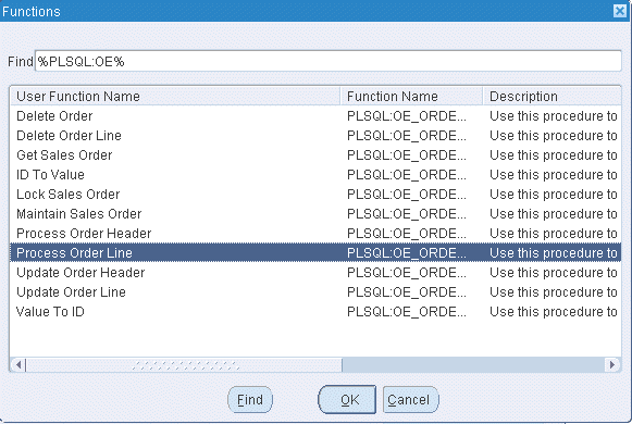
Based on your Composite application, select appropriate functions and then grant permissions to the API that you will be invoking from the BPEL process or Mediator.
For example, for a sales order line change BPEL process, you select sales order line change related functions contained in the order change PL/SQL API and group them as a permission set, and then grant the permission set to an appropriate user through a role.
See: Creating a User Role.
Menus Page
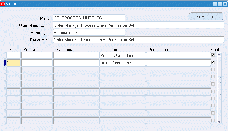
Save the Permission Set.
Permission sets are granted through user roles. Therefore, you must first create a role and then assign the role to a user.
Use the following steps to create a user role:
Log in to Oracle E-Business Suite using the User Management responsibility.
Select Roles & Role Inheritance from the Navigator to access the Roles & Role Inheritance page.
Click Create Role to access the Create Role page.
Enter the following information to create a role:
Category: Select Miscellaneous from the drop-down list.
Role Code: Enter an appropriate role code (such as 'EBS_ADAPTER_ROLE').
Display Name: Enter appropriate information for the display name (such as 'EBS Adapter Role').
Description: Enter appropriate information for the description (such as 'EBS Adapter Role').
Application: Select an appropriate application (such as 'Application Object Library').
Active Date: Enter an appropriate date which is earlier than or equal to today's date so that the role can become valid right away.
Save the information and click Create Grant.
Enter the following information in the Create Grant: Define Grant page:
Name: Enter an appropriate name (such as 'EBS_ADAPTER_GRANT').
Description: Enter description information for this grant.
Click Next.
In the Create Grant: Define Object Parameters and Select Set page, select the Permission Set you created earlier in the Creating a Permission Set section and click Next.
Click Finish.
Use the following steps to grant a permission set to a user through a role:
Log in to Oracle E-Business Suite using the User Management responsibility.
Select Users from the Navigator to access the User Maintenance page.
Search for the user you want to assign the role and click Go.
Select the Update icon next to the user name that you want to assign the role.
In the Update User page, click Assign Roles to have the Search window populated which allows you to search for the role that you created earlier.
Select the role (such as 'EBS_ADAPTER_ROLE') and save your update.
Oracle E-Business Suite Adapter provides flexfield support for PL/SQL APIs and Open Interface Tables (OIT). If a PL/SQL API or an OIT table is configured with flexfields, flexfield information including flexfield data and mapping will not only be displayed at design time, but also be included in the XSD. This helps integration developers to create mappings between third party data elements with more meaningful business object elements. Additionally, this feature allows Oracle E-Business Suite Adapter run time to work in the context of flexfields.
Note: This feature is available for PL/SQL APIs and Open Interface Tables only and is for Oracle E-Business Suite Release 12 and above.
What is a Flexfield?
Flexfield is one of the essential features in Oracle E-Business Suite. It provides a flexible way to represent objects or to implement context-sensitive fields that appear only when needed. It is a field made up of sub-fields, or segments. Two flexfield types (key and descriptive flexfields) are used to let you customize Oracle E-Business Suite features without additional programming. To provide the unique, customized information that conforms to your business needs, Oracle E-Business Suite Adapter provides flexfield support for PL/SQL APIs and Open Interface Tables that contain flexfields.
How Flexfield Data is Configured at Design Time
At design time during the partner link creation, if a PL/SQL API or an open interface table is configured with flexfields, appropriate flexfield information is displayed along with the API parameters or table columns in the right pane of the Oracle E-Business Suite Module Browser. You can optionally modify or create a new flexfield mapping for the selected interface, or proceed with the partner link creation without configuring the interface with flexfields.
To configure flexfield data, Oracle E-Business Suite Adapter allows you to either use an existing flexfield mapping that has been created earlier, or to create a new mapping if desired. In the case of creating a new mapping, a mapping flexfield wizard appears guiding you through each configuration page where you can add key and descriptive flexfields with desired mapping for the selected interface.
Key Features
Flexfield feature provided in Oracle E-Business Suite Adapter includes the following key features:
It displays flexfield information which contains the mapping of API parameter or interface table column names and the corresponding flexfield segment names in the Oracle E-Business Suite Module Browser.
It lets you configure and modify both key flexfields and descriptive flexfields.
It provides a flexible mapping support mechanism for a selected API or an open interface table that you can configure a new mapping or reuse a previously created mapping through import.
Note: A flexfield can be mapped only once. Duplicate flexfields are not allowed.
It allows you to use more than one open interface table during the partner link creation. Flexfields can be configured individually for each table.
Once a flexfield mapping is completed and partner link is created, an enhanced schema (XSD) is generated using flexfield names instead of the generic parameter or column names.
It allows the Oracle E-Business Suite Adapter run time to work in conjunction with the support from Oracle Database Adapter to handle the enhanced schema.
Oracle E-Business Suite Adapter supports both key flexfields and descriptive flexfields referenced by an API or open interface table.
Key Flexfields
Use key flexfields as identifiers for entities. Generally, the identifier you create using a key flexfield is required by the application. For example, an Accounting Flexfield is used to create and display account numbers. This key flexfield is owned by Oracle General Ledger, but its values can be used by many of the applications.
A key flexfield structure usually consists of multiple segments and each segment contains meaningful information. For example, the Accounting Flexfield structure can consist of five segments such as Company, Department, Account, Sub-Account, and Product.
Descriptive Flexfields
Use descriptive flexfields to gather additional specialized, important, and unique information required by your business. In other words, this type of flexfield is used to collect information beyond what is collected by Oracle E-Business Suite.
A descriptive flexfield typically uses multiple structures. Each of these structures can have different segments to gather different data. Each segment's value is stored in a column in one of the application's base tables. The column name reflects the type of flexfield data it holds.
In general, key flexfields store their data in columns called SEGMENTn; descriptive flexfields store their data in columns called ATTRIBUTEn, where n is a number. Use key flexfields to define your own structure for many of the identifiers required by Oracle E-Business Suite; use descriptive flexfields to gather additional information about your business entities beyond the information required by Oracle E-Business Suite.
For more information about flexfields, see the Oracle E-Business Suite Flexfields Guide.
Flexfield Mapping Concepts
Each flexfield regardless of its type has its owner application. For example, an Accounting Flexfield is owned by Oracle General Ledger application. During the flexfield configuration, you need to first select an application to which a flexfield belongs, and then select a flexfield name (such as Accounting Flexfield) contained in the selected application (such as General Ledger).
Key Flexfield Mapping for PL/SQL APIs
The following diagram illustrates the high level key flexfield mapping concepts for PL/SQL APIs:
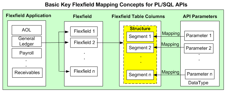
In this diagram, Flexfield 2 (Accounting Flexfield) belongs to General Ledger application, and it contains multiple segments (segment 1 to segment n) which can be grouped by data type.
The main part of flexfield configuration is mapping. Once a flexfield with a desired application is selected, the matching segments (segment 1 to segment n) are derived from the Oracle E-Business Suite database along with the related API parameters based on the flexfield metadata for your mapping.
For PL/SQL APIs, parameters are displayed based on the selected data type (parent type or record type). API parameters and the flexfield table columns can be mapped either manually or automatically by using Auto Map.
Parent type: Parent type is a pseudo type to allow all the scalar parameters at the procedure level to participate in the mapping. It can be used for simple APIs that just have scalar parameters.
Record type: Record type can be selected if it's for a complex API that has record types in addition to scalar types. When a record type occurs multiple times in the API, the list of paths is displayed for reference. If the parameters from a record type are mapped to the flexfield table columns, then the same mapping would be applicable to all the paths it occurs.
Supported record types include array, nested tables, and associated arrays.
Note: Automapping feature maps all the table columns to the parameters which have the column name as part of the parameter name. For examples, parameter P_ATTRIBUTE1 would be mapped to a column name called ATTRIBUTE1, and parameter P_ATTRIBUTE2 would be mapped to a column name called ATTRIBUTE2.
Once mapping is completed, you will need to select a flexfield structure for a key flexfield.
Note: A flexfield structure is a specific configuration of segments. If you add or remove segments, or rearrange the order of segments in a flexfield, you get a different structure. The segments that make up a particular structure are logically or functionally related. The structure and segment definition is created in Oracle E-Business Suite through the Application Developer responsibility.
For more information about flexfields, see the Oracle E-Business Suite Flexfields Guide.
Key Flexfield Mapping for Open Interface Tables
Similar to the mapping for PL/SQL APIs, once a flexfield with a desired application is selected for an Open Interface Table, the matching segments (segment 1 to segment n) are derived from Oracle E-Business Suite database along with the related open interface table columns based on the flexfield metadata for your mapping. Mapping can be performed either manually or automatically by using Auto Map.
Note: Please note that datatype is used for PL/SQL APIs only.
Automapping feature maps all the flexfield table columns to the open interface table columns which have the flexfield table column name as part of the interface table column name. For examples, interface table column name TP_ATTRIBUTE1 would be mapped to a flexfield table column name called ATTRIBUTE1, and interface table column TP_ATTRIBUTE2 would be mapped to a flexfield table column name called ATTRIBUTE2.
The following diagram illustrates the high level key flexfield mapping concepts for Open Interface Tables:
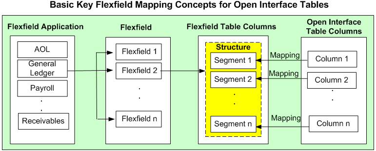
Once mapping is completed, you will need to select a flexfield structure for a key flexfield.
Descriptive Flexfield Mapping for PL/SQL APIs
For descriptive flexfields, an additional mapping is required for the context column. All the flexfield table columns including the context column should be mapped to the scalar parameters within one record type or parent type. Once mapping is completed, select at least one context value for the selected context column for a descriptive flexfield.
For example, Chile uses 'Region' and 'Comuna' in addition to 'State' and 'County' to represent subdivision or relatively small location geographically. Similarly, Ecuador uses 'Zona' and 'Parroquia' in geography to describe different boundaries. This is a perfect example using a descriptive flexfield to customize the application to meet your business needs. Chile and Ecuador are the context values when defining the descriptive flexfield 'TCA Location Information'. Parameter1 (or Parameter2) is mapped to ATTRIBUTE1 (or ATTRIBUTE2) whose value depends on the selected context value (either 'Chile' or 'Ecuador').
Note: For descriptive flexfields, context value should be available to the runtime through an API parameter.
The following diagram illustrates the high level descriptive flexfield mapping concepts for PL/SQL APIs:
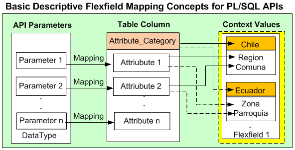
Descriptive Flexfield Mapping for Open Interface Tables
Similar to PL/SQL APIs, an additional mapping is also required for the context column in defining descriptive flexfield mapping for Open Interface Tables. All the flexfield table columns including the context column should be mapped to the open interface table columns. Once mapping is completed, select at least one context value for the selected context column for a descriptive flexfield.
The following diagram illustrates the high level descriptive flexfield mapping concepts for Open Interface Tables:
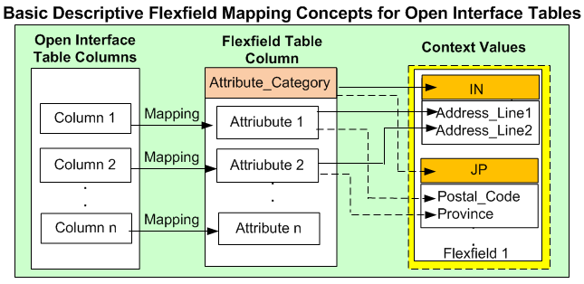
In this diagram, for example, 'Address_Line1' and 'Address_Line2' are selected for 'IN' (India) to describe the address information, while the same attributes (ATTRIBUTE1 and ATTRIBUTE2) are mapped to 'Postal_Code' and 'Province' for 'JP' (Japan).
Oracle E-Business Suite Adapter uses the flexfield mapping defined from the Oracle E-Business Suite Module Browser to generate the enhanced XSD. This XSD will contain flexfield segment names based on the mapping chosen at design time. Oracle E-Business Suite Adapter will then work in conjunction with Oracle Database Adapter to handle the enhanced schema file for runtime processing.
Guidelines for Defining Flexfield Structure and Context Values
You will not be able to select a context value for a descriptive flexfield or a structure for a key flexfield if one of the following conditions are met:
A context/structure has no segments or segment mappings.
Only context/structure values that have at least one segment can be selected.
A context/structure has segments, but none of them matches with at least one of the table columns mapped in the mapping page.
A context/structure has all the segments disabled in Oracle E-Business Suite.
A context/structure itself is disabled in Oracle E-Business Suite.
Only context/structure that is enabled will be shown in the Flexfield Subflow wizard in step 6 (Flexfield Subflow - Configure Flexfields).
Flexfield mapping will be used to generate an enhanced schema or XSD file.
Duplicate flexfields are not allowed. A flexfield can be mapped only once.
Range key flexfields are not supported.
Valuesets and qualifiers are not supported.
For PL/SQL APIs, flexfield mapping for all the flexfield segments in one flexfield should happen either at the parent level or within one record type.
For PL/SQL APIs, the mapping for the context column should correspond to parameters at the level at which the segments are mapped. In other words, if the descriptive flexfield segments are mapped to a selected data type (either record type or parent type) for PL/SQL APIs, the context column mapping should also happen with the same selected data type.
While creating a partner link at design time, if a selected interface is configured with flexfields, Oracle E-Business Suite Module Browser will display flexfield information in the right pane of the browser window.
For example, search for a PL/SQL API called SYNC_ACCT_ORDER or select it from HZ_AIA_CUSTOM_PKG listed under the Other Interfaces > Custom Objects > PLSQL APIs node. The flexfield data if configured in this API is displayed in the Oracle E-Business Suite Module Browser.
Oracle E-Business Suite Module Browser Showing an API with Flexfield Mapping Information
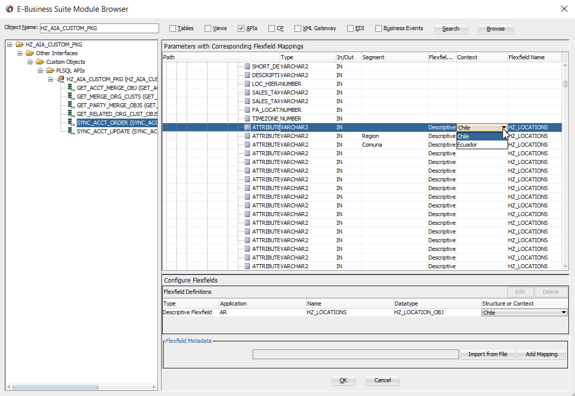
Note: If a selected API or an interface table has pre-configured flexfield mappings available, a pop-up window appears allowing you to decide if you want to use these pre-configured mappings. Click Yes to display these mappings as part of the flexfield definitions in the Configure Flexfields region. You can modify them later if needed.
Click No to indicate that you will not use these mappings and the pop-up window disappears.
Understanding Flexfield Mapping Data in Oracle E-Business Suite Module Browser
The flexfield information associated with the selected interface can be populated and configured in the following regions of the Oracle E-Business Suite Module Browser:
Note: Alternatively, you can bypass the flexfield mapping configuration or modification for your selected interface by simply clicking OK in the browser to proceed with the partner link creation.
Parameters (or Interface Table Columns) with Corresponding Flexfield Mappings Region
This region displays the parameters or interface table columns of the selected interface along with the corresponding flexfield mapping information.
For PL/SQL APIs, record type parameters are displayed as a tree structure within the table, allowing you to expand or collapse the tree nodes to locate your desired parameters. For Open Interface Tables, interface table column names are simply listed in the table.
Configure Flexfields Region
This region allows you to perform the following tasks:
Modifying Flexfield Mapping Definitions
No matter if the selected interface is a custom or seeded one, once the flexfield mapping information is populated in the browser, you can modify context values for a descriptive flexfield and structure for a key flexfield.
Oracle E-Business Suite Adapter will then use the flexfield definitions from the Module Browser to generate the enhanced XSD. This XSD will contain the flexfield segment names chosen at design time based on the mapping information along with the parameter or table column names.
For more information on how to modify your flexfield mappings, see Modifying Flexfield Mapping Definitions.
Creating a New Mapping
You can create a new mapping for a selected interface by clicking Add Mapping in the Flexfield Metadata section. A new flexfield mapping wizard appears guiding you through each configuration page where you can add key and descriptive flexfields, as well as configure flexfield mapping between the selected interface and any flexfields defined in the Oracle E-Business Suite instance.
Importing an Existing Mapping
Instead of creating a new mapping, you can use an existing mapping that has been created earlier by clicking Import from File in the Flexfield Metadata section. This lets you select a desired flexfield mapping for your selected interface.
Once a desired mapping is imported, you can modify the context values for a descriptive flexfield and structure for a key flexfield if needed to meet your needs.
Reviewing Flexfield Mapping Configuration Files
Once a partner link is created, an enhanced XSD file along with flexfield configuration and mapping files are generated. You can review these files for flexfield details. See: Reviewing Flexfield Mapping Configurations.
After performing a search or browsing through the list of interfaces available in Oracle E-Business Suite Module Browser, if a selected PL/SQL interface or an open interface table is configured with flexfields, then flexfield information in the API or the table will be displayed in the right pane of the window.
To add or configure a new mapping for the selected API or open interface table, click Add Mapping in the Configure Flexfields region. A series of flexfield selection pages in the wizard appear guiding you to configure a new mapping for your selected API or interface table.
Flexfield Subflow - Welcome
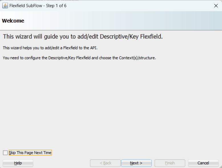
After you click Next in the Welcome page, the Select Flexfield Type page appears where you can choose either a key or descriptive flexfield to be configured or added for your flexfield.
Flexfield Subflow - Select Flexfield Type
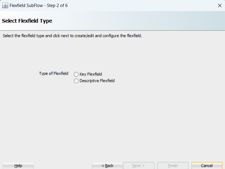
Select either the Key Flexfield or Descriptive Flexfield radio button for your flexfield configuration.
Please note that you can configure more than one key or descriptive flexfield for the selected API or open interface table to meet your business needs.
See:
Configuring Key Flexfield Mappings for an Open Interface Table
Configuring Descriptive Flexfield Mappings for an Open Interface Table
Sample Business Scenario
Take the INV_EBI_ITEM_PUB.PROCESS_ITEM_LIST API as an example to explain the inbound web service creation with flexfield data.
When a request is placed for processing inventory item list from a third party application, the key flexfield data as part of the input payload is routed and the PL/SQL API INV_EBI_ITEM_PUB.PROCESS_ITEM_LIST is invoked to update the item list in Oracle E-Business Suite. The updated data will be passed to the client as the response message.
The following diagram illustrates the service invocation process flow:
Inbound Service Invocation with Flexfield Data

After deploying the service, you can validate the process by querying inventory item list directly from Oracle E-Business Suite application. The retrieved item data should be the same as input from the payload.
Configuring a Key Flexfield Mapping As Part of the Partner Link Creation
To configure a key flexfield mapping for the selected API INV_EBI_ITEM_PUB.PROCESS_ITEM_LIST, click Add Mapping in the Configure Flexfields region. A series of flexfield selection pages in the wizard appear guiding you to configure a new mapping for your selected API.
Click Next in the Welcome page. The Select Flexfield Type page is displayed.
Flexfield Subflow - Select Flexfield Type
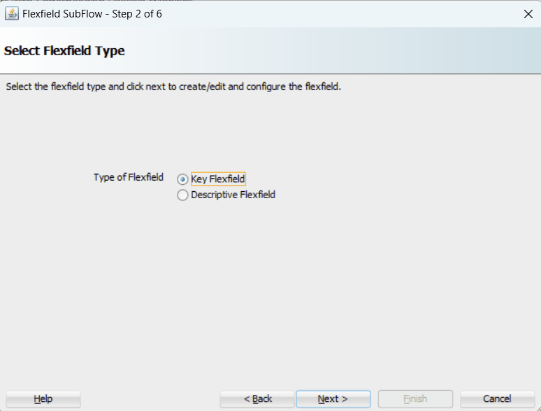
Perform the following steps to configure a key flexfield:
Select the Key Flexfield radio button in the Select Flexfield Type page. Click Next. The Select Flexfield Application page appears.
To locate your desired application name, enter keyword search (such as '%App%') and click Query to execute the search. All the entries that match your search criteria will be displayed. For example, select the Inventory radio button as the application name to which the flexfield belongs.
Flexfield Subflow - Select Flexfield Application
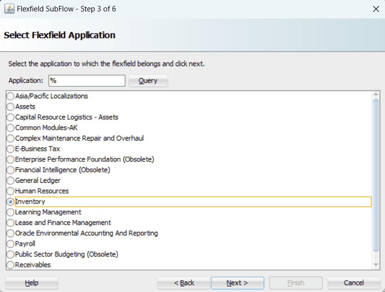
Alternatively, click Query directly to execute the blank search without keyword search. This displays all flexfield application names for your selection.
Click Next.
In the Select Flexfield page, enter keyword search if desired and click Query to execute the search. All the matched key flexfields are displayed for your selection. Select your desired key flexfield radio button.
Flexfield Subflow - Select Flexfield
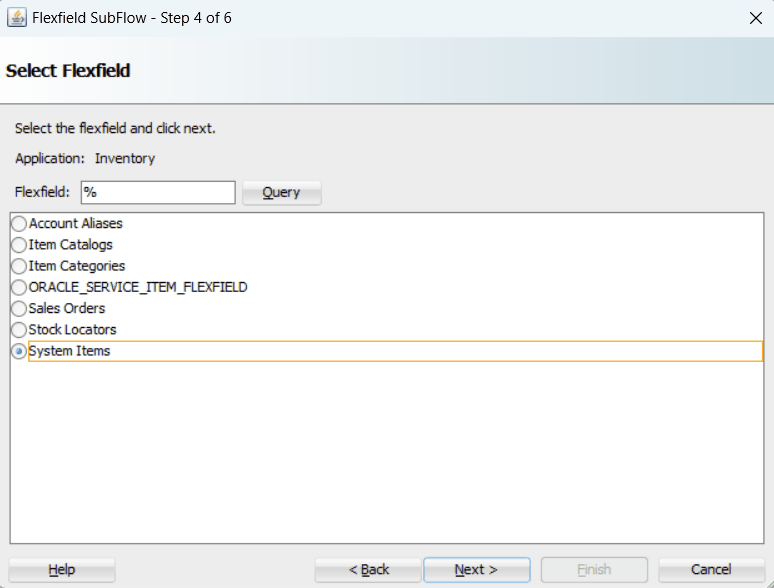
Click Next to continue.
The Select Datatype and Configure Mapping page appears where you can choose desired mapping for your key flexfield. Notice that your selected key flexfield name is automatically populated as the Flexfield name.
Flexfield Subflow - Select Datatype and Configure Mapping
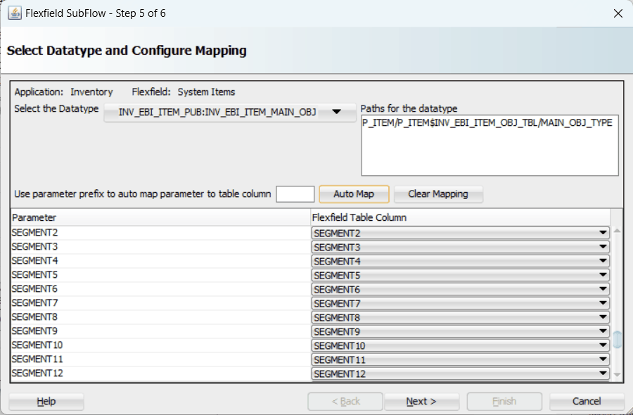
To configure flexfield mapping, select the <Parent_type> from the Select the Datatype drop-down list if it's a simple API which does not have record types. This retrieves all needed flexfield metadata from Oracle E-Business Suite database and populates parameters at the parent level for your mapping.
Note: Parent_type is a pseudo type to allow all the scalar parameters at the procedure level to participate in the mapping.
You can also select record type if it's for a complex API. When a record type occurs multiple times in the API, the list of paths is displayed for reference. If the parameters from a record type are mapped to the flexfield table columns, then the same mapping would be applicable to all the paths it occurs.
In this mapping page, you have the option to do the mapping manually or use automapping feature.
Automapping feature maps all the segments to the parameters, which have the column name as part of the parameter name. For example, table column SEGMENT1 would be mapped to parameter SEGMENT1. If there are multiple sets of parameters and the table column names, then the prefix can be specified.
For example, enter 'P_' as the prefix to retrieve all parameters starting with 'P_', such as P_SEGMENT1, P_SEGMENT2, P_SEGMENT3, to P_SEGMENTn where n is a number. If you click Auto Map, all the parameters with prefix 'P_' are automatically displayed along with the automapped table column names.
Note: Flexfield values are stored in the application database tables. In general, key flexfields store their data in columns called SEGMENTn and descriptive flexfields store their data in columns called ATTRIBUTEn, where n is a number.
Manual mapping lets you select a desired table column for a corresponding parameter.
Note: If a parameter has already mapped to a table column, you cannot remap the parameter to other column. In this situation, 'Mapped to other Flexfield' appears instead for the mapped parameter.
Click Clear Mapping to clear current mapping you have. All previously mapped columns marked with 'Mapped to other Flexfield' will not be removed from the system.
Click Next to continue.
The configuration of the flexfield will not be complete without a structure for a key flexfield and at least one context value for a descriptive flexfield.
In the Configure Flexfields page, enter keyword search if desired in the Structure field or simply click Query to execute a blank search. All the matched structures for the selected key flexfield are displayed.
Select only one structure (such as SYSTEM_ITEMS).
Please note that there are certain criteria need to be met in order to have your desired structures displayed in the wizard for selection. See: Guidelines for Defining Flexfield Structure and Context Values.
Flexfield Subflow - Configure Flexfields
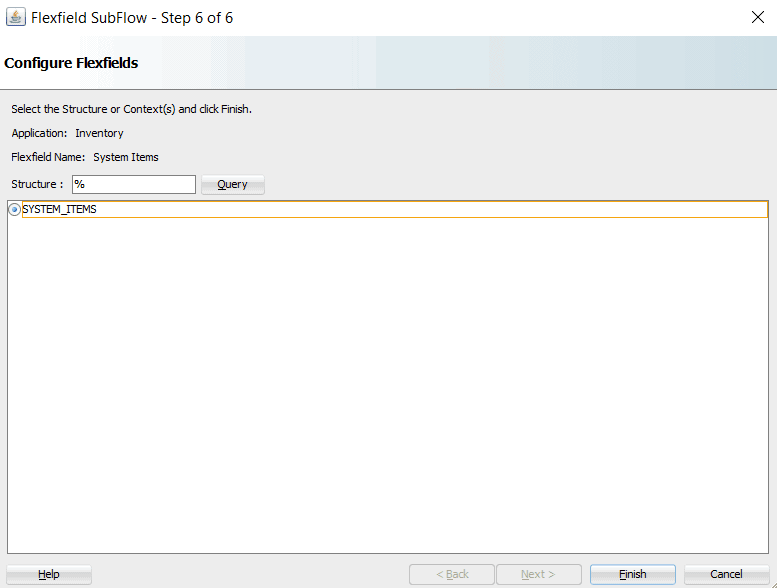
Note: Only one structure for a key flexfield can participate in flexfield mapping. In the case of a descriptive flexfield, multiple context values can participate in the mapping.
Click Finish.
The Oracle E-Business Suite Module Browser window appears. The newly added key flexfield structure and mapped parameters are displayed in the Parameters with Corresponding Flexfield Mappings region.
The key flexfield information is also displayed in the Flexfield Definitions section.
Oracle E-Business Suite Module Browser with Selected Key Flexfield Information
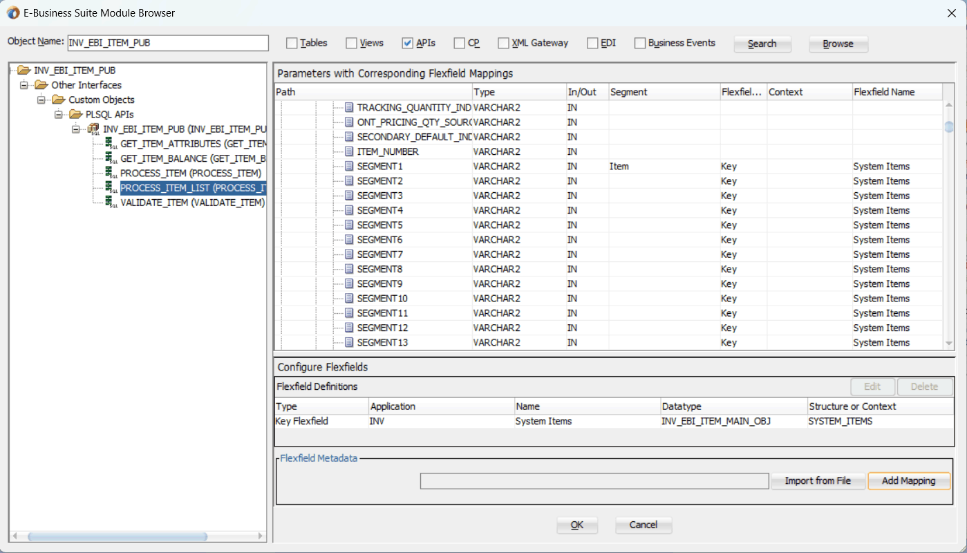
Click OK.
The Application Interface page appears with the selected API.
Application Interface Page with Selected API
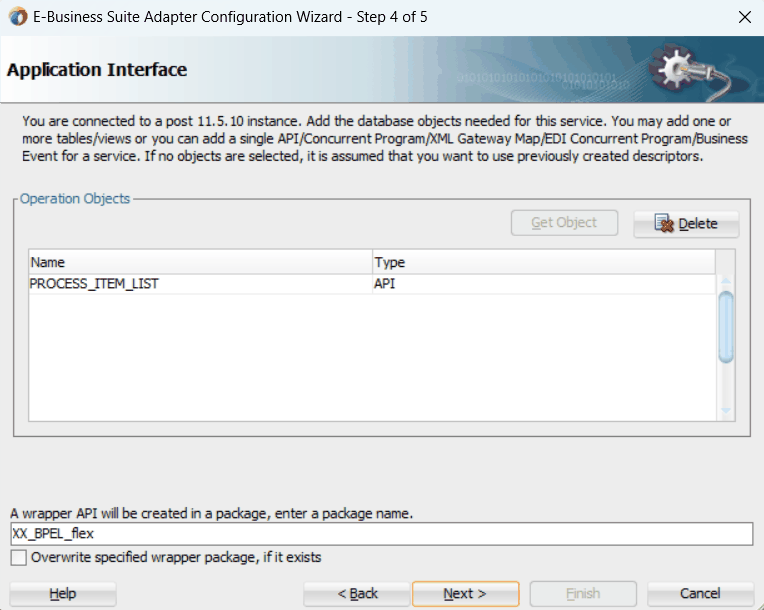
Click Next and then click Finish.
The wizard generates the WSDL file corresponding to the partner link. An enhanced XSD file, for example ProcessItem_KFF_flex.xsd, is also created. This XSD file contains the schema describing the procedure arguments with the elements representing the parameters that have been replaced with flexfield segment names.
Click Apply and then OK.
Additionally, configuration file and flexfield mapping file are created. For more information on these files, see Reviewing Flexfield Mapping Configurations.
To add descriptive flexfield mappings for the selected API, see Configuring Descriptive Flexfield Mappings for a PL/SQL API.
The key flexfield mapping data configured earlier during the partner link creation can be shown at design time.
A Composite Example with Key Flexfield Mappings
Here is an example describing the key flexfield mapping in the BPEL process of a SOA composite:
Create a new SOA composite application with BPEL process
Add a partner link service called ProcesItem_KFF with key flexfield mapping that we configured earlier for the INV_EBI_ITEM_PUB.PROCESS_ITEM_LIST API
For information on how to configure key flexfield mappings, see Configuring Key Flexfield Mappings for a PL/SQL API.
Add a partner link for File Adapter to read input payload that contains flexfield data for service invocation
In the File Directories dialog, enter the physical directory (such as /usr/tmp) where the input payload xml file (such as input_payload.xml) resides.
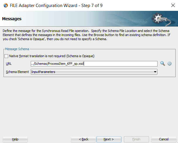
In the Messages dialog, select the 'browse for schema file' icon next to the URL field to open the Type Chooser.
Click Type Explorer and select Project Schema Files > ProcessItem_KFF_sp.xsd > ProcessItem_KFF_flex.xsd > InputParameters.
Type Chooser Dialog with Message Schema Selected
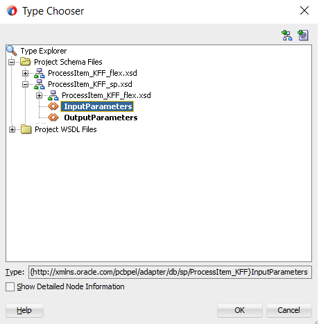
Click OK. The selected schema information will be automatically populated in the URL and Schema Element fields.
Messages Page
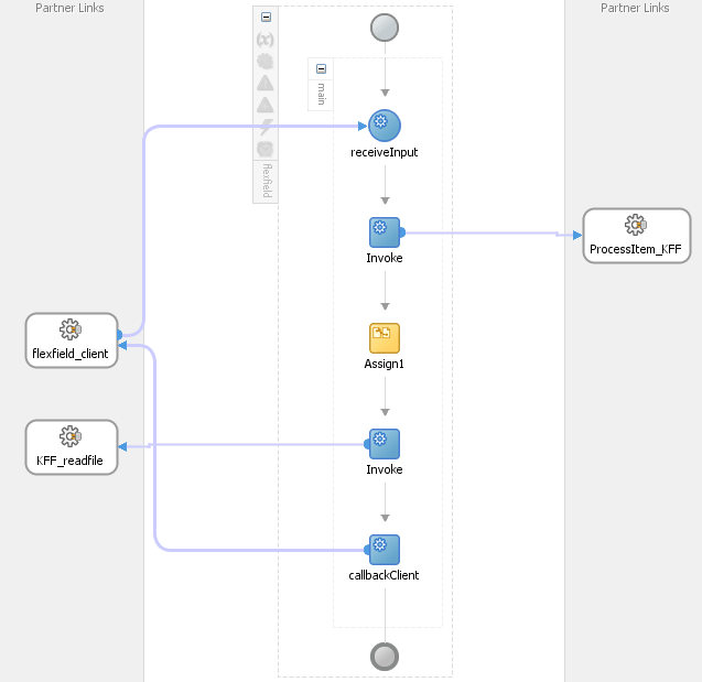
Configure two Invoke activities
Associate the first Invoke activity with the File Adapter partner link to synchronously read input payload data
Associate the second Invoke activity with the partner link ProcessItem_KFF that contains flexfield mapping to invoke the service
Add an Assign activity to pass input payload received from the File Adapter to the second Invoke activity for service invocation
Mapped key flexfield column names corresponding to the flexfield matching segments defined in the Oracle E-Business Suite are displayed in the Assign activity. See: Assigning Parameters with Key Flexfields in the Assign Activity.
BPEL Process Diagram in SOA Composite
For more information on how to create design time tasks, see Design-Time Tasks for PL/SQL APIs.
Flexfield Validation in Oracle E-Business Suite
When defining key flexfield segments for a key flexfield 'System Items' in Oracle Inventory application (Application Developer responsibility), only SEGMENT1 is specified as 'Item' in the Segments Summary - System Items window.
Key Flexfield Segments Summary for System Items
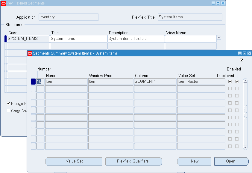
The following table explains the relationship between the key flexfield mapping data and the actual segments defined in Oracle E-Business Suite:
| Key Flexfield Segments Mapped During Flexfield Configuration | Key Flexfield Segments Defined in Oracle E-Business Suite |
|---|---|
| SEGMENT1 | Item |
| SEGMENT2 | Not defined |
| SEGMENTn | Not defined |
Mapped segment column names for the key flexfield 'System Items' are displayed in the Oracle E-Business Suite Module Browser once the mapping is complete. In this case, only 'Item', the corresponding column name in SEGMENT1, is shown here.
Oracle E-Business Suite Module Browser with Mapped Segment Column Name 'Item'

For information on how to define key flexfields and key flexfield segments, refer to the Planning and Defining Key Flexfields chapter, Oracle E-Business Suite Flexfields Guide.
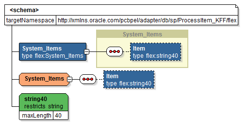
Flexfield Validation in the Schema File
Select the enhanced XSD file (for example ProcessItem_KFF_flex.xsd
Schema File with Mapped Key Flexfield
Assigning Parameters with Key Flexfields in the Assign Activity
In the Assign activity of the BPEL process diagram within the SOA composite application, the mapped key flexfield can be displayed and used to pass an input variable from payload to the second Invoke activity for service invocation.
Edit Assign Dialog with a Mapped Key Flexfield Parameter
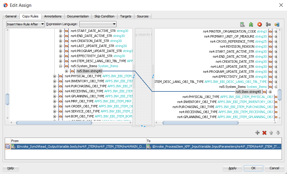
Use Assign activity to provide input payload information to the Item object of the target parameter.
Note: The target parameter ns2:SEGMENT1 mapped to the column name SEGMENT1 during the key flexfield configuration earlier is now translated into ns3:Item (under ns2:System_Items) and displayed in the Assign activity.
In the From navigation tree, navigate to Variables > Process > Variables > Invoke_SynchRead_OutputVariable > body > ns2:InputParameters > ns2:P_ITEM > ns2:P_ITEM_ITEM > ns2:MAIN_OBJ_TYPE (datatype INV_EBI_ITEM_MAIN_OBJ) > ns2: System_Items and select ns3: Item.
In the To navigation tree, navigate to Variables > Process > Variables > Invoke1_ProcessItem_KFF_InputVariable > InputParameters > ns2:InputParameters > ns2:P_ITEM > ns2:P_ITEM_ITEM > ns2:MAIN_OBJ_TYPE (datatype INV_EBI_ITEM_MAIN_OBJ) > ns2: System_Items and select ns3: Item.
Drag the source node (ns3: Item) to connect to the target node (ns3: Item) that you just specified. This creates a line that connects the source and target nodes. The copy rule is displayed in the From and To sections at the bottom of the Edit Assign dialog box.
Click Apply and OK to complete the Assign activity.
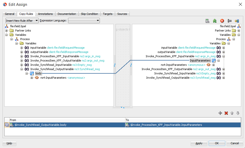
Note: Alternatively, since 'ns2:InputParameters' variables contained in the Source and Target are identical, you can simply drag the source node (ns2:InputParameters) to connect to the target node (ns2:InputParameters) and complete the Assign activity.
Edit Assign Dialog with Mapped Parameters
Please note that the datatype INV_EBI_ITEM_MAIN_OBJ shown here is exact the same datatype (INV_EBI_ITEM_PUB:INV_EBI_ITEM_MAIN_OBJ) specified earlier from the drop-down list in the Select Datatype and Configure Mapping page. P_ITEM is listed as the paths for the selected datatype.
Select Datatype and Configuring Mapping Page

After deploying the BPEL process contained in a SOA Composite application (FlexfieldKFF) to the Oracle WebLogic managed server (for example 'soa-server1'), the key flexfields we configured earlier are displayed in the soa-server1 server (http://<servername>:<portnumber>/soa-infra) allowing you to specify payload data and test the service invocation.
Note: Please note that you can also test and manage the process from the Oracle Enterprise Manager Fusion Middleware Control. In this example, the mapped key flexfield used as part of the input payload happens to be located or nested within multiple sub-levels down from the top. This means that we need to drill down to the mapped key flexfield Item by expanding the parameter nodes multiple times from the top level (Payload > P_ITEM > P_ITEM_ITEM > MAIN_OBJ_TYPE > System_Items > Item). However, Oracle Enterprise Manager Fusion Middleware Control has certain limitations on displaying payload parameters if they are nested too deeply.
Therefore, in this case we access the mapped key flexfield directly from the soa-infra in the soa-server1 server.
For information on how to test the service invocation from the Oracle Enterprise Manager Fusion Middleware Control, see Test the deployed SOA Composite application with BPEL process.
The Test Web Services Test Client page is displayed with your selected project. Click Test. The key flexfield configured earlier will be displayed as part of the input payload in the Parameters region of the Web Services Test Client page.
Parameters Region with Key Flexfields Displayed
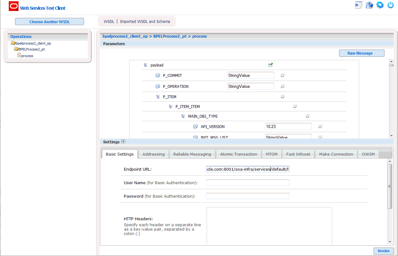
In the Parameters region, expand the Payload > P_ITEM > P_ITEM_ITEM > MAIN_OBJ_TYPE > System_Items. Mapped key flexfield 'Item' is displayed as part of the payload.
Parameters Region with Mapped Key Flexfield 'Item' Highlighted
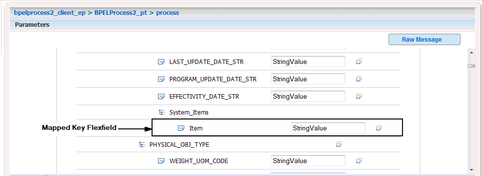
Enter appropriate data as payload and then click Invoke to invoke the service.
Sample Business Scenario
Take the HZ_AIA_CUSTOM_PKG.SYNC_ACCT_ORDER API as an example to explain the inbound web service creation with flexfield data.
When a request is placed for synchronizing customer information from a third party application, the descriptive flexfield data as part of the payload is routed and the PL/SQL API HZ_AIA_CUSTOM_PKG.SYNC_ACCT_ORDER is invoked to update the organization and customer accounts in Oracle E-Business Suite. The synchronized customer data will be passed to the client as the response message.
The following diagram illustrates the service invocation process flow:
Inbound Service Invocation with Flexfield Data

After deploying the service, you can validate the process by querying customer data directly from Oracle Customer Online application. The retrieved customer data should be the same as input from the payload.
Configuring a Descriptive Flexfield Mapping As Part of the Partner Link Creation
To configure a descriptive flexfield mapping for the selected API HZ_AIA_CUSTOM_PKG.SYNC_ACCT_ORDER, click Add Mapping in the Configure Flexfields region. A series of flexfield selection pages in the wizard appear guiding you to configure a new mapping for your selected API.
Click Next in the Welcome page. The Select Flexfield Type page is displayed.
Flexfield Subflow - Select Flexfield Type
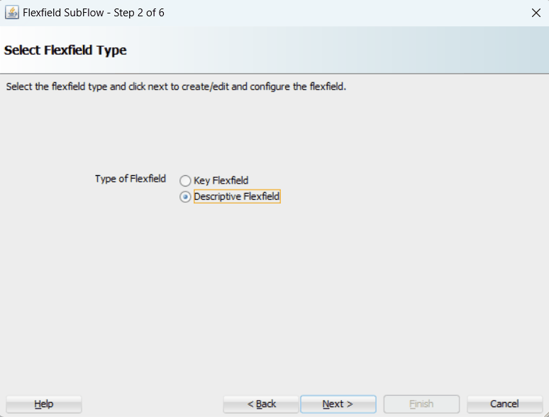
Perform the following steps to configure a descriptive flexfield:
Select the Descriptive Flexfield radio button in the Select Flexfield Type page, and then use the similar approach as described earlier for key flexfields in the flexfield mapping wizard.
Click Next in the Select Flexfield Type page. The Select Flexfield Application page is displayed.
To locate your desired application, enter keyword search (such as '%App%') or simply click Query to execute the search. All the matched applications for descriptive flexfield are displayed. For example, select the Receivables radio button as the application name to which the descriptive flexfield belongs.
Flexfield Subflow - Select Flexfield Application
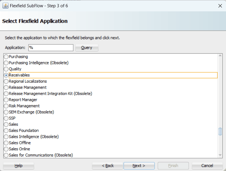
Click Next.
In the Select Flexfield page, enter keyword search (such as 'HZ%') if desired and click Query to execute the search. All the matched descriptive flexfields are displayed for your selection.
Select your desired descriptive flexfield (such as HZ_LOCATIONS) and click Next.
Flexfield Subflow - Select Flexfield
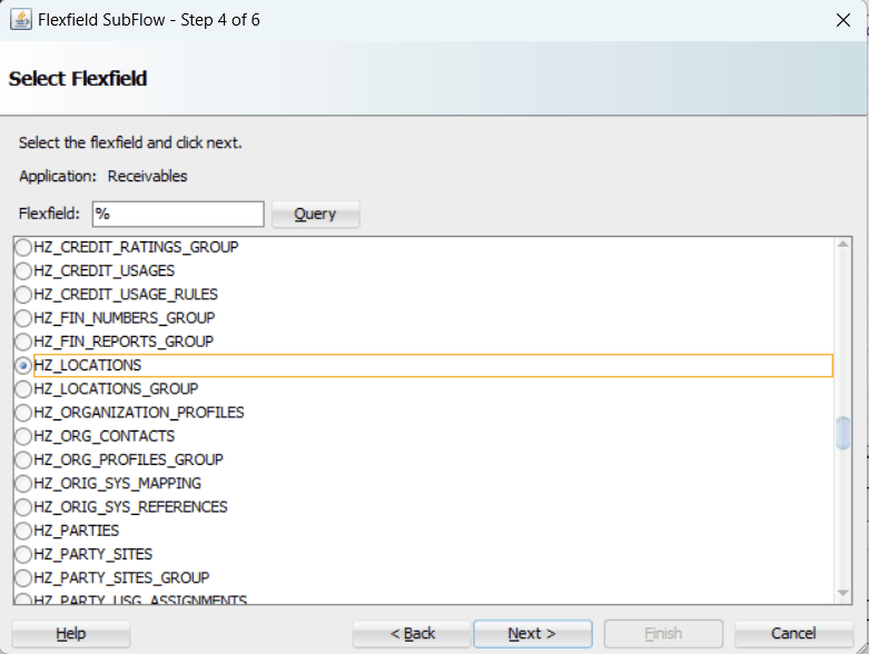
The Select Datatype and Configure Mapping page appears where you can choose desired mapping for your descriptive flexfield.
Notice that your selected descriptive flexfield name HZ_LOCATIONS is automatically populated as the Flexfield name.
Flexfield Subflow - Select Path and Configure Mapping
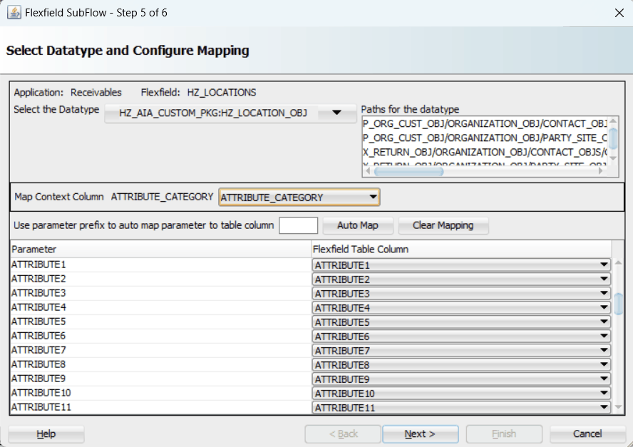
To configure flexfield mapping, select a desired data type from the Datatype drop-down list. This retrieves all needed flexfield metadata from Oracle E-Business Suite database and populates parameters at the parent level for your mapping.
Parent type: Parent type is a pseudo type to allow all the scalar parameters at the procedure level to participate in the mapping. It can be used for simple APIs that just have scalar parameters.
Record type: Record type can be selected if it's a complex API that has record types in addition to scalar types.
Selecting Context Column for Descriptive Flexfield Mapping
For descriptive flexfields, you need to perform an additional mapping for the context column. This is because flexfield mapping cannot span across record types. All the table columns including the context column should be mapped to the scalar parameters within one record type or parent type.
In the Map Context Column ATTRIBUTE_CATEGORY field, select a desired category name that you want to view the mapping information from the drop-down list. For example, select ATTRIBUTE_CATEGORY from the drop-down list.
Note: If a parameter has already mapped to a table column, you cannot remap the parameter to other column. In this situation, 'Mapped to other Flexfield' appears instead for the mapped parameter.
Similar to key flexfields, the mapping can be performed manually or assisted with the automapping feature by clicking Auto Map.
Automapping feature maps all the table columns to the parameters, which have the column name as part of the parameter name. For example, table column names from ATTRIBUTE1 to ATTRIBUTE20 are automatically displayed and mapped to parameters from ATTRIBUTE1 to ATTRIBUTE20 respectively through automapping.
If there are multiple sets of parameters and the table column names, then the prefix needs to be specified for automapping. This would map the potential parameters which need to be considered for the mapping. Enter parameter prefix (such as 'INDUSTRY_') to first locate your desired parameters that you want the automapping to be performed. Next, click Auto Map. All the parameters with prefix 'INDUSTRY_' are automatically displayed along with the automapped table column names. Parameter 'INDUSTRY_ATTRIBUTE1' is mapped to column ATTRIBUTE1, and parameter 'INDUSTRY_ATTRIBUTEn' is mapped to column ATTRIBUTEn.
Instead of using automapping feature, you can manually select a desired table column name from the drop-down list for a corresponding parameter for your flexfield mapping.
Click Clear Mapping to clear current mapping you have in the table column only. All previously mapped columns marked with 'Mapped to other Flexfield' will not be removed from the system.
Click Next to proceed to the next page.
In the Configure Flexfields page, select at least one context value for the selected descriptive flexfield. For example, select desired context values (such as Chile and Ecuador).
You can either enter keyword search in the Context field or simply click Query to execute the search before selection.
For descriptive flexfields, context value should be available to the runtime through an API parameter.
Please note that there are certain criteria need to be met in order to have your desired context values displayed in the wizard for selection. See: Guidelines for Defining Flexfield Structure and Context Values.
Flexfield Subflow - Configure Flexfields
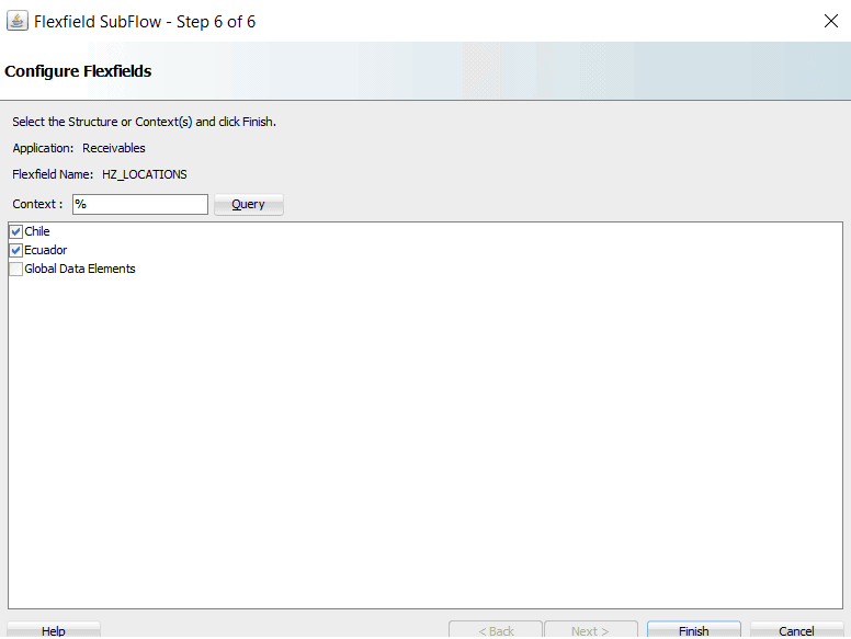
Click Finish to complete the flexfield configuration.
The Oracle E-Business Suite Module Browser window appears. The newly added descriptive flexfield information including the segment values for the selected context value is displayed in the right pane of the window.
Oracle E-Business Suite Module Browser with Selected Descriptive Flexfield Information

Click OK.
The Application Interface page appears with the selected API.
Application Interface Page
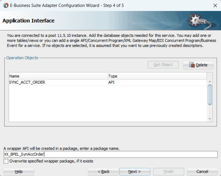
Click Next and then click Finish.
The wizard generates the WSDL file corresponding to the partner link. An enhanced XSD file, for example SynAccOrder_flex.xsd, is also created. This XSD file contains the schema describing the procedure arguments with the elements representing the parameters that have been replaced with flexfield segment names.
Click Apply and then OK.
Additionally, configuration file and flexfield mapping file are created. For more information on these files, see Reviewing Flexfield Mapping Configurations.
Once a new flexfield mapping has been configured or added, if modification is needed, you can make updates by first selecting desired flexfield type that you want to modify and then make needed changes. For more information on how to modify the selected mapping details, see Modifying Flexfield Mapping Definitions.
Similar to key flexfield mappings, the descriptive flexfield mapping data configured earlier during the partner link creation can be shown at design time along with the following activities orchestrated in the BPEL process within in a SOA composite:
A Composite Example with Descriptive Flexfield Mappings
Here is an example describing the descriptive flexfield mappings in the BPEL process of a SOA composite:
Create a new SOA composite application with BPEL process
Add a partner link service called SynAccOrder with descriptive flexfield mappings that we configured earlier for the HZ_AIA_CUSTOM_PKG.SYNC_ACCT_ORDER API
For information on how to configure descriptive flexfield mappings, see Configuring Descriptive Flexfield Mappings for a PL/SQL API.
Add a partner link for File Adapter to read input payload that contains flexfield data for service invocation
In the File Directories dialog, enter the physical directory (such as /usr/tmp) where the input payload xml file (such as input_payload.xml) resides.
In the Messages dialog, select the 'browse for schema file' icon next to the URL field to open the Type Chooser.
Click Type Explorer and select Project Schema Files > SynAccOrder_sp.xsd > SynAccOrder_flex.xsd > InputParameters.
Type Chooser Dialog with Flexfield Schema
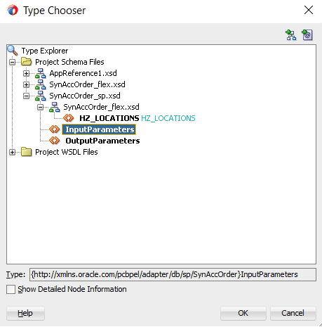
Click OK. The selected schema information will be automatically populated in the URL and Schema Element fields.
Messages Page
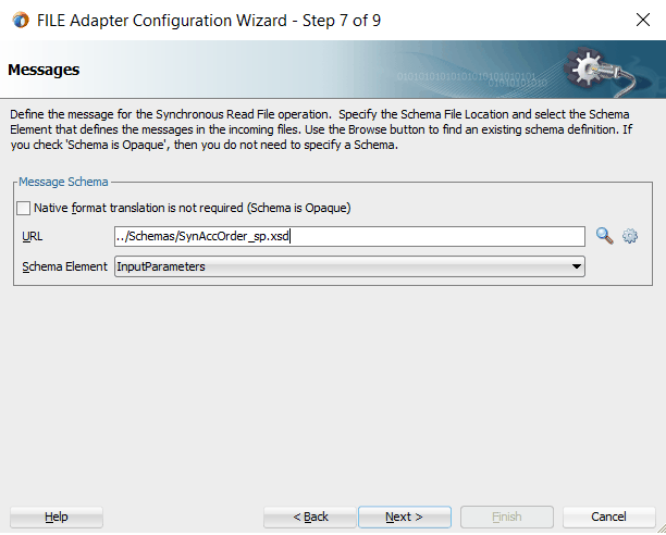
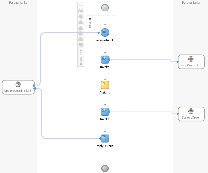
Configure two Invoke activities
Associate the first Invoke activity with the File Adapter partner link to synchronously read input payload data
Associate the second Invoke activity with the partner link SynAccOrder that contains flexfield mapping to invoke the service.
Add an Assign activity to pass input payload received from the File Adapter to the second Invoke activity for service invocation
Mapped descriptive flexfield column names corresponding to the flexfield matching segments defined in the Oracle E-Business Suite are displayed in the Assign activity. See: Assigning Parameters with Descriptive Flexfields in the Assign Activity.
BPEL Process Diagram
For more information on how to create design time tasks, see Design-Time Tasks for PL/SQL APIs.
Flexfield Validation in Oracle E-Business Suite
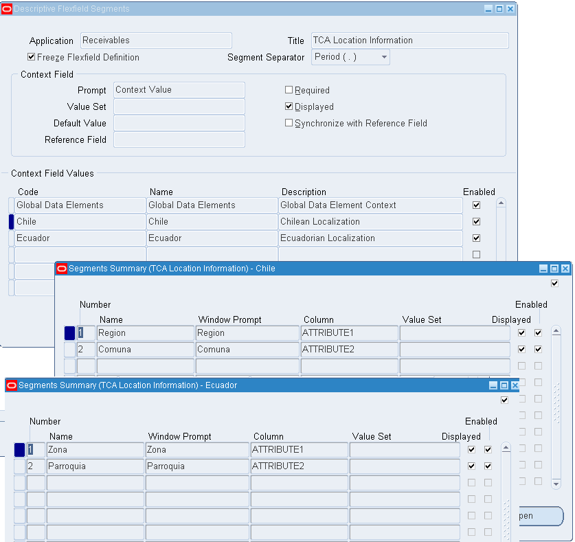
When defining descriptive flexfield attributes for 'TCA Location Information' (HZ_LOCATIONS) in Oracle Receivables application (Application Developer responsibility), the following attributes are specified based on context values:
| Context Value | ATTRIBUTE1 | ATTRIBUTE2 |
|---|---|---|
| Chile | Region | Comuna |
| Ecuador | Zona | Parroquia |
Descriptive Flexfield Segments Summary for System Items
Flexfield Validation in the Schema File
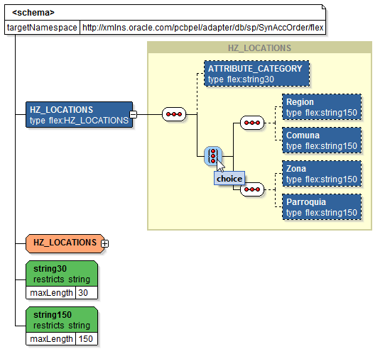
Select the enhanced XSD file (such as SynAccOrder_flex.xsd) in Oracle JDeveloper and notice that the mapped descriptive flexfields are displayed with type 'flex' under the HZ_LOCATIONS flexfield as part of the schema.
Additionally, the mapped table column names (Region, Comuna, Zona, and Parroquia) are grouped by context value (Chile and Ecuador) listed in a tree structure. Context value nodes are connected with the <choice> icon indicating that only either one of the context values and its associated table columns can be selected.
Schema File with Context Values
Assigning Parameters with Descriptive Flexfields in the Assign Activity
In the Assign activity of the BPEL process diagram within the SOA composite application, the mapped descriptive flexfields can be displayed and used to pass an input variable received from payload to the Invoke activity for SynAccOrder service invocation.
Edit Assign Dialog with Mapped Descriptive Flexfields
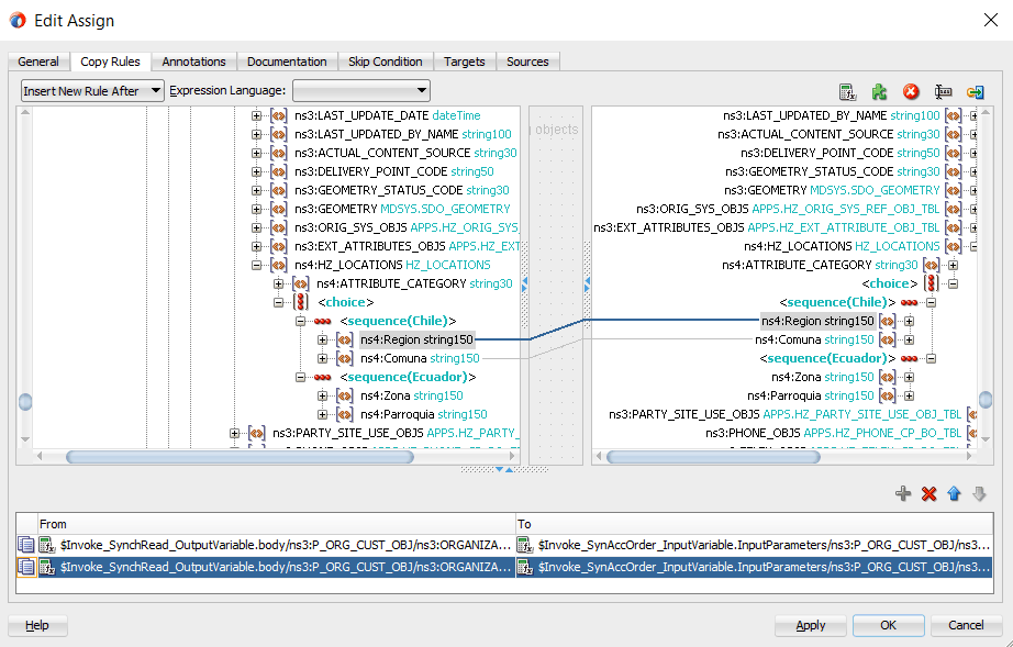
Use Assign activity to provide input payload information to the TCA Location object of the target parameter.
The target parameters ns2:ATTRIBUTE1 was mapped to the following descriptive flexfield columns during the flexfield configuration earlier:
Region (under context value <sequence(Chile)>)
Zona (under context value <sequence(Ecuador)>)
The target parameters ns2:ATTRIBUTE2 was mapped to the following descriptive flexfield columns during the flexfield configuration earlier:
Comuna (under context value <sequence(Chile)>)
Parroquia (under context value <sequence(Ecuador)>)
These descriptive flexfield columns grouped by context value are displayed in the Assign activity.
In the From navigation tree, navigate to Variables > Process > Variables > Invoke_SynchRead_OutputVariable > body > ns2:InputParameters > ns2:P_ORG_CUST_OBJ > ns2:ORGANIZATION_OBJ > ns2:PARTY_SITE_OBJS> ns2:PARTY_SITE_OBJS_ITEM > ns2:LOCATION_OBJ >ns2:HZ_LOCATIONS >ns3:ATTRIBUTE_CATEGORY and expand the <choice> icon to locate the mapped descriptive flexfield columns ns3:Region and ns3:Comuna for the selected context value ns3:Chile (or select ns3:Zona and ns3:Parroquia for the selected context value ns3:Ecuador instead).
In the To navigation tree, navigate to Invoke_SyncOrder_InputVariable > InputParameters > ns2:InputParameters > ns2:P_ORG_CUST_OBJ > ns2:ORGANIZATION_OBJ > ns2:PARTY_SITE_OBJS> ns2:PARTY_SITE_OBJS_ITEM > ns2:LOCATION_OBJ >ns2:HZ_LOCATIONS >ns3:ATTRIBUTE_CATEGORY and expand the <choice> icon to locate the mapped descriptive flexfield columns ns3:Region and ns3:Comuna for the selected context value ns3:Chile (or select ns3:Zona and ns3:Parroquia for the selected context value ns3:Ecuador instead).
To assign the parameters with descriptive flexfields in the Assign activity, drag the source node (ns3:Region) to connect to the first target node (ns3:Region) that you just specified. This creates a line that connects the source and target nodes. The copy rule is displayed in the From and To sections at the bottom of the Edit Assign dialog box.
Repeat the procedure to assign the second parameter by dragging the same source node (ns3:Comuna) to connect to the second target node (ns3:Comuna). The second copy rule is displayed in the From and To sections at the bottom of the Edit Assign dialog box.
Click Apply and OK to complete the Assign activity.
Note: Alternatively, since 'ns2:InputParameters' variables contained in the Source and Target are identical, you can simply drag the source node (ns2:InputParameters) to connect to the target node (ns2:InputParameters) and complete the Assign activity.
Edit Assign with Descriptive Flexfields
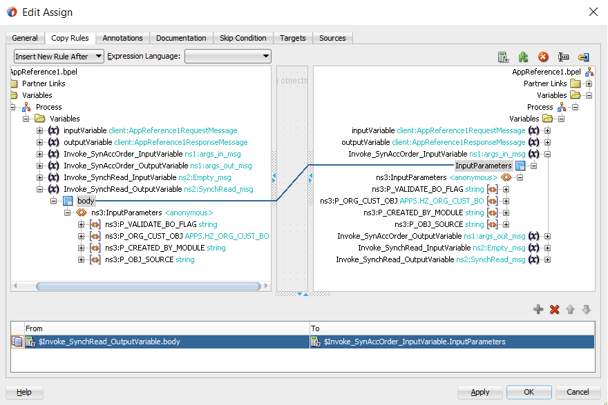
After deploying the BPEL process contained in a SOA Composite application to the Oracle WebLogic managed server (such as 'soa-server1'), the descriptive flexfields we configured earlier are displayed in the soa-server1 server (http://<servername>:<portnumber>/soa-infra) allowing you to specify payload data and test the service invocation. Please note that you also test and manage the process from the Oracle Enterprise Manager Fusion Middleware Control.
Note: You can also test and manage the process from the Oracle Enterprise Manager Fusion Middleware Control. In this example, the mapped descriptive flexfields used as part of the input payload happen to be located or nested within multiple sublevels down from the top. This means that we need to drill down to the mapped descriptive flexfields (Region and Comuna) by expanding the parameter nodes multiple times from the top level (Payload > P_ORG_CUST_OBJ > ORGANIZATION_OBJ > PARTY_SITE_OBJS > PARTY_SITE_OBJS_ITEM > LOCATION_OBJ > HZ_LOCATIONS > ATTRIBUTE_CATEGORY > HZ_LOCATIONS_1 to view descriptive flexfields). However, Oracle Enterprise Manager Fusion Middleware Control has certain limitations on displaying payload parameters if they are nested too deeply.
Therefore, in this case we access the mapped descriptive flexfields directly from the soa-infra in the soa-server1 server.
For information on how to test the service invocation from the Oracle Enterprise Manager Fusion Middleware Control, see Test the deployed SOA Composite application with BPEL process.
Similar to the key flexfield project described earlier, click the deployed descriptive flexfield project in the Welcome to the Oracle SOA/BPM Platform on WebLogic page.
The Web Services Test Client page is displayed with your selected project. Click Test. The descriptive flexfields configured earlier will be displayed as part of the input payload in the Parameters region of the Web Services Test Client page.
In the Parameters region, expand the Payload > P_ORG_CUST_OBJ node and navigate to ORGANIZATION_OBJ > PARTY_SITE_OBJS > PARTY_SITE_OBJS_ITEM > LOCATION_OBJ > HZ_LOCATIONS > ATTRIBUTE_CATEGORY > HZ_LOCATIONS_1.
Two sets of descriptive flexfields configured earlier at the design time are now displayed at the runtime.
HZ_LOCATIONS_1_0 (This is the default selection we configured in the Assign activity at the design time.)
Region
Comuna
HZ_LOCATIONS_1_1
Zona
Parroquia
Enter appropriate data as payload and then click Invoke to invoke the service.
Sample Business Scenario
Take an open interface table ONT.OE_HEADERS_IFACE_ALL as an example to explain the inbound web service creation with flexfield data.
When a request of inserting order data for a specific account is received, order data details can be customized based on the requestor's needs using both key flexfields and descriptive flexfields. This data will then be passed as an input payload and inserted into the open interface table. The inserted data can be selected and written as an output file and returned back as a response message for client verification.
The following diagram illustrates the service invocation process flow:
Inbound Service Invocation with Flexfield Data

After deploying the service, you can validate the process directly by viewing the output XML file. This data should be the same as input from the payload.
Configuring a Key Flexfield Mapping As Part of the Partner Link Creation
In this example, use key flexfields for a specific order needs (such as a special account number, its associated account name, and so on) for the selected open interface table ONT.OE_HEADERS_IFACE_ALL.
To configure a key flexfield mapping, click Add Mapping in the Configure Flexfields region. A series of flexfield selection pages in the wizard appear guiding you to configure a new mapping for your selected open interface table.
Click Next in the Welcome page. The Select Flexfield Type page is displayed.
Flexfield Subflow - Select Flexfield Type

Perform the following steps to configure a key flexfield:
Select the Key Flexfield radio button in the Select Flexfield Type page. Click Next. The Select Flexfield Application page appears.
To locate your desired application name, enter keyword search (such as '%App%') and click Query to execute the search. All the entries that match your search criteria will be displayed. For example, select the Application Object Library radio button as the application name to which the flexfield belongs.
Flexfield Subflow - Select Flexfield Application
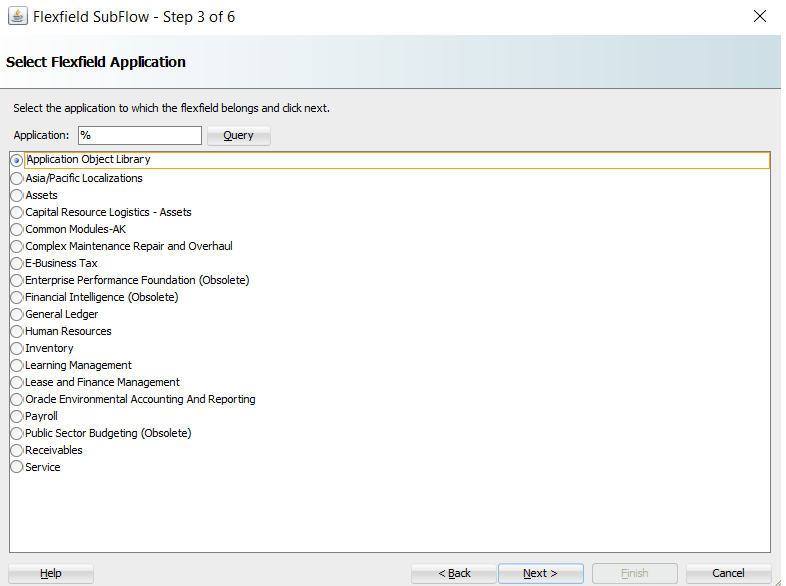
Alternatively, click Query directly to execute the blank search without keyword search. This displays all flexfield application names for your selection.
Click Next.
In the Select Flexfield page, enter keyword search if desired and click Query to execute the search. All the matched key flexfields are displayed for your selection. Select your desired key flexfield radio button, such as "Sample Adapter KFF".
Click Next to continue.
The Configure Mapping page appears where you can choose desired mapping for your key flexfield. Notice that your selected key flexfield name is automatically populated as the Flexfield name.
In this mapping page, you have the option to do the mapping manually or use automapping feature.
Automapping feature maps all the flexfield segments to the Open Iinterface Table columns, which have the column name as part of the parameter name. For example, flexfield table column SEGMENT1 would be mapped to interface table column TP_SEGMENT1. If there are multiple sets of interface table columns and the flexfield table column names, then the prefix can be specified.
For example, enter 'TP_' as the prefix to retrieve all interface table columns starting with 'TP_', such as TP_SEGMENT1, TP_SEGMENT2, TP_SEGMENT3, to TP_SEGMENTn where n is a number. If you click Auto Map, all the interface table columns with prefix 'TP_' are automatically displayed along with the automapped flexfield table column names.
Note: Flexfield values are stored in the application database tables. In general, key flexfields store their data in columns called SEGMENTn and descriptive flexfields store their data in columns called ATTRIBUTEn, where n is a number.
Manual mapping lets you select a desired flexfield table column for a corresponding interface table column.
Note: If an interface table column has already mapped to a flexfield table column, you cannot remap that column to other flexfield table column. In this situation, 'Mapped to other Flexfield' appears instead for that mapped interface table column.
Click Clear Mapping to clear current mapping you have. All previously mapped columns marked with 'Mapped to other Flexfield' will not be removed from the system.
Click Next to continue.
The configuration of the flexfield will not be complete without a structure for a key flexfield and at least one context value for a descriptive flexfield.
In the Configure Flexfields page, enter keyword search if desired in the Structure field or simply click Query to execute a blank search. All the matched structures for the selected key flexfield are displayed.
Select only one structure (such as "AU_BANK_DETAILS").
Please note that there are certain criteria need to be met in order to have your desired structures displayed in the wizard for selection. See: Guidelines for Defining Flexfield Structure and Context Values.
Note: Only one structure for a key flexfield can participate in flexfield mapping. In the case of a descriptive flexfield, multiple context values can participate in the mapping.
Click Finish.
The Oracle E-Business Suite Module Browser window appears. The newly added key flexfield structure and mapped interface table columns are displayed in the Interface Table Columns with Corresponding Flexfield Mappings region.
The key flexfield information is also displayed in the Flexfield Definitions section.
Oracle E-Business Suite Module Browser Displaying an Open Interface Table with Key Flexfield Information
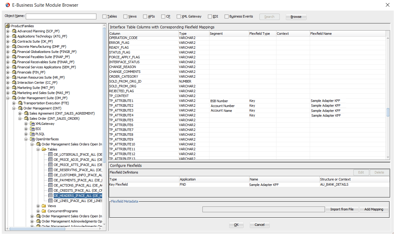
Click OK if you complete your flexfield configuration. The Application Interface page appears with the selected open interface table.
In this example, we will cerate a descriptive flexfield mapping to this selected open interface table by clicking Add Mapping. See: Configuring Descriptive Flexfield Mappings for an Open Interface Table.
Based on the same business scenario described earlier, a special order applying for customers both in India and Japan needs to be inserted to ONT.OE_HEADERS_IFACE_ALL open interface table. After the special order data is inserted, a written output file containing those data is requested as part of a response message for the requestor.
Configuring a Descriptive Flexfield Mapping As Part of the Partner Link Creation
In this example, descriptive flexfields are used to represent address requirements for customers located in different countries.
To configure a descriptive flexfield mapping for the selected open interface table ONT.OE_HEADERS_IFACE_ALL, click Add Mapping in the Configure Flexfields region. A series of flexfield selection pages in the wizard appear guiding you to configure a new mapping for your selected API.
Click Next in the Welcome page. The Select Flexfield Type page is displayed.
Flexfield Subflow - Select Flexfield Type

Perform the following steps to configure a descriptive flexfield:
Select the Descriptive Flexfield radio button in the Select Flexfield Type page, and then use the similar approach as described earlier for key flexfields in the flexfield mapping wizard.
Click Next in the Select Flexfield Type page. The Select Flexfield Application page is displayed.
To locate your desired application, enter keyword search (such as '%App%') or simply click Query to execute the search. All the matched applications for descriptive flexfield are displayed. For example, select the Oracle Application Library radio button as the application name to which the descriptive flexfield belongs.
Flexfield Subflow - Select Flexfield Application
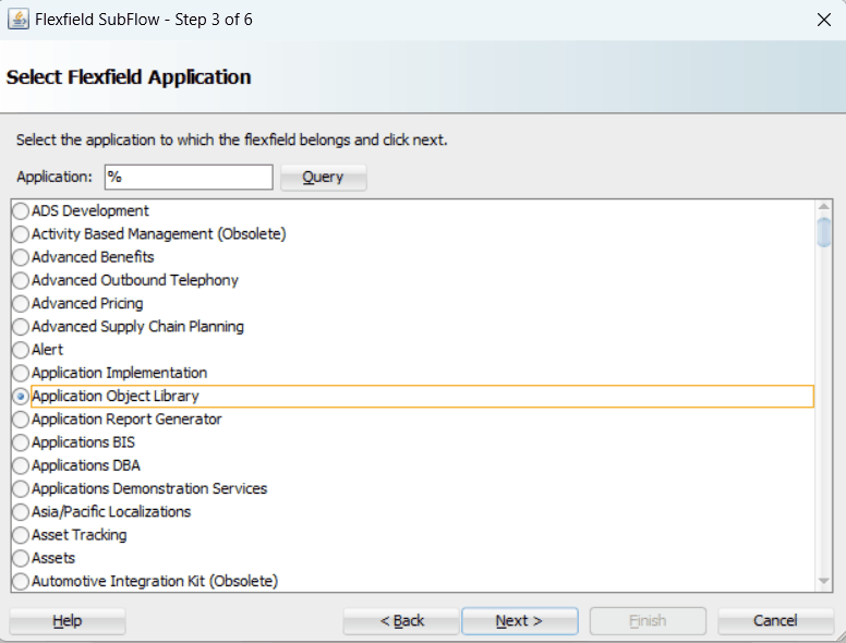
Click Next.
In the Select Flexfield page, enter keyword search (such as 'FND%') if desired and click Query to execute the search. All the matched descriptive flexfields are displayed for your selection.
Select your desired descriptive flexfield (such as FND_FLEX_TEST) and click Next.
Flexfield Subflow - Select Flexfield
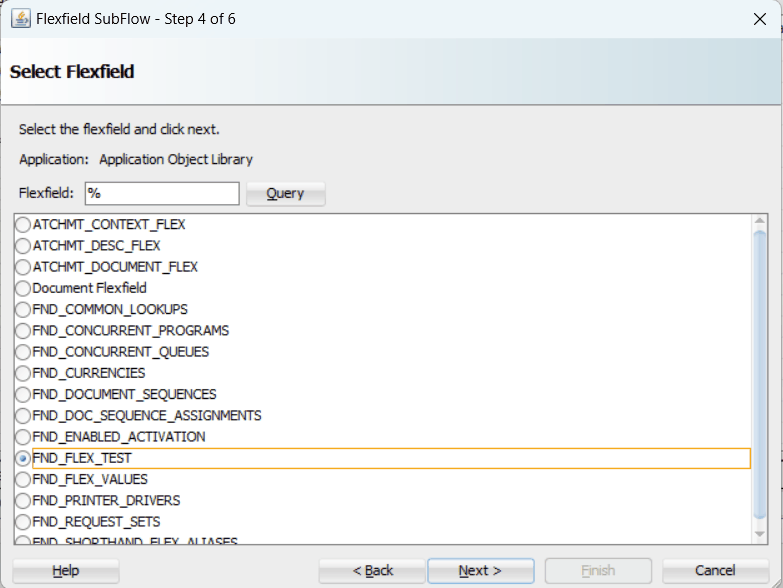
The Configure Mapping page appears where you can choose desired mapping for your descriptive flexfield.
Notice that your selected descriptive flexfield name FND_FLEX_TEST is automatically populated as the Flexfield name.
Flexfield Subflow - Configure Mapping
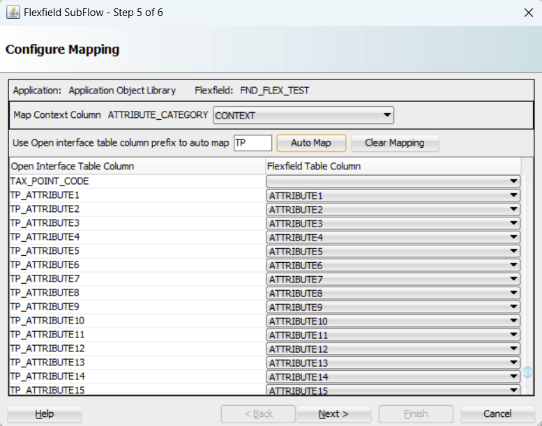
Selecting Context Column for Descriptive Flexfield Mapping
For descriptive flexfields, you need to perform an additional mapping for the context column. This is because flexfield mapping cannot span across open interface tables. All the flexfield table columns including the context column should be mapped to the open interface table columns in the OIT table.
In the Map Context Column ATTRIBUTE_CATEGORY field, select a desired category name that you want to view the mapping information from the drop-down list. For example, select CONTEXT from the drop-down list.
Note: If an open interface table column has already mapped to a flexfield table column, you cannot remap that column to other flexfield table column. In this situation, 'Mapped to other Flexfield' appears instead for that mapped open interface table column.
Flexfield Subflow - Configure Mapping for Context Column
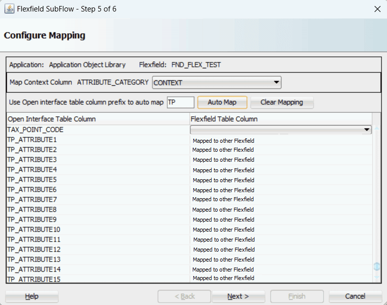
Similar to key flexfields, the mapping can be performed manually or assisted with the automapping feature by clicking Auto Map.
Automapping feature maps all the flexfield table columns to the open interface table columns, which have the column name as part of the interface table column name. For example, flexfield table column names from ATTRIBUTE1 to ATTRIBUTE20 are automatically displayed and mapped to the open interface table columns from ATTRIBUTE1 to ATTRIBUTE20 respectively through automapping.
If there are multiple sets of open interface table columns and the flexfield table column names, then the prefix needs to be specified for automapping. This would map the potential open interface table columns which need to be considered for the mapping. Enter table column prefix (such as 'TP') to first locate your desired interface table columns that you want the automapping to be performed. Next, click Auto Map. All the interface table columns with prefix 'TP' are automatically displayed along with the automapped table column names. Interface table column 'TP_ATTRIBUTE1' is mapped to column ATTRIBUTE1, and interface table column 'TP_ATTRIBUTEn' is mapped to column ATTRIBUTEn.
Instead of using automapping feature, you can manually select a desired flexfield table column name from the drop-down list for a corresponding interface table column for your flexfield mapping.
Click Clear Mapping to clear current mapping you have in the flexfield table column only. All previously mapped columns marked with 'Mapped to other Flexfield' will not be removed from the system.
Click Next to proceed to the next page.
In the Configure Flexfields page, select at least one context value for the selected descriptive flexfield. For example, select desired context values (such as 'IN' and 'JP').
You can either enter keyword search in the Context field or simply click Query to execute the search before selection.
For descriptive flexfields, context value should be available to the run time through an open interface table column.
Please note that there are certain criteria need to be met in order to have your desired context values displayed in the wizard for selection. See: Guidelines for Defining Flexfield Structure and Context Values.
Flexfield Subflow - Configure Flexfields
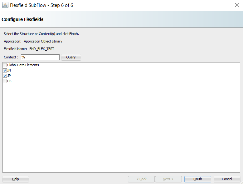
Click Finish to complete the flexfield configuration.
The Oracle E-Business Suite Module Browser window appears. The newly-added descriptive flexfield information including the segment values for the selected context value is displayed in the right pane of the window.
Oracle E-Business Suite Module Browser Displaying an Open Interface Table with Descriptive Flexfield Information
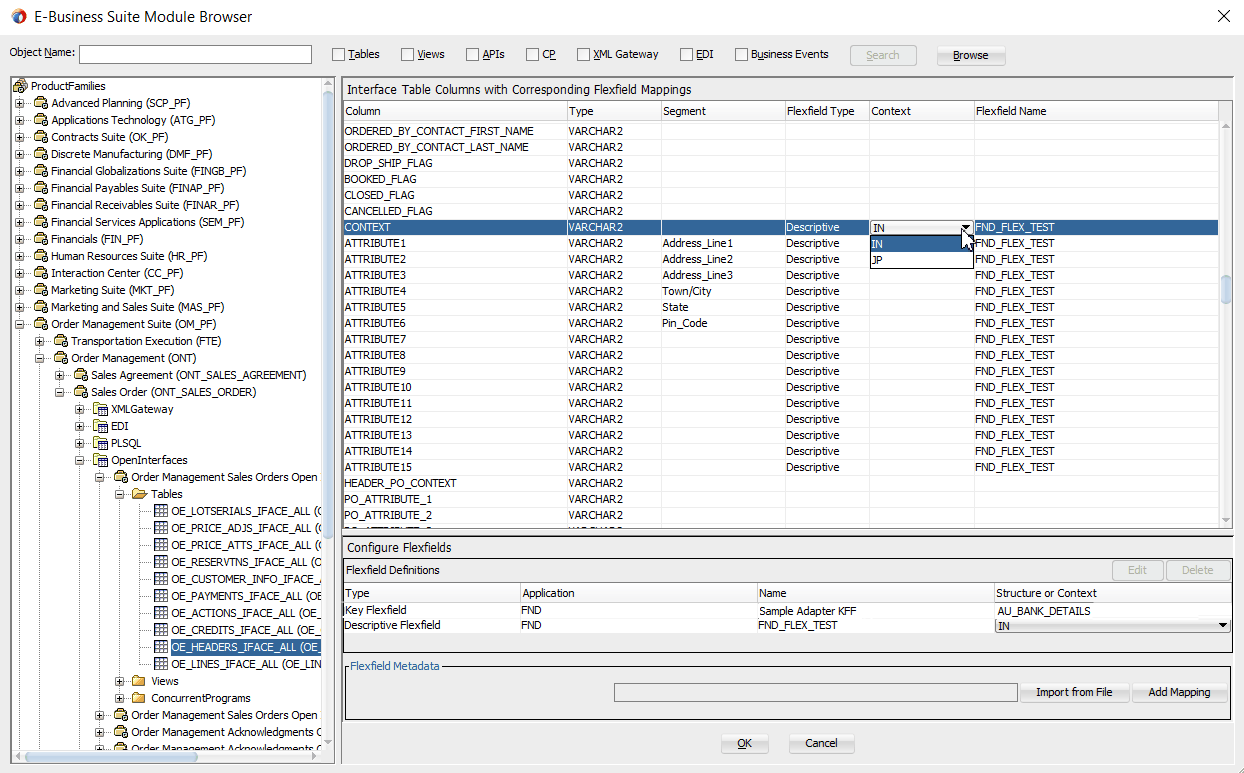
Click OK.
The Application Interface page appears with the selected open interface table.
Application Interface Page
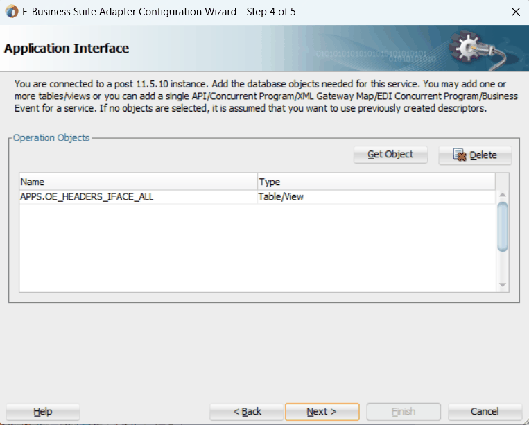
Click Next.
The Operation Type page is displayed.
Adapter Configuration Wizard - Operation Type Page
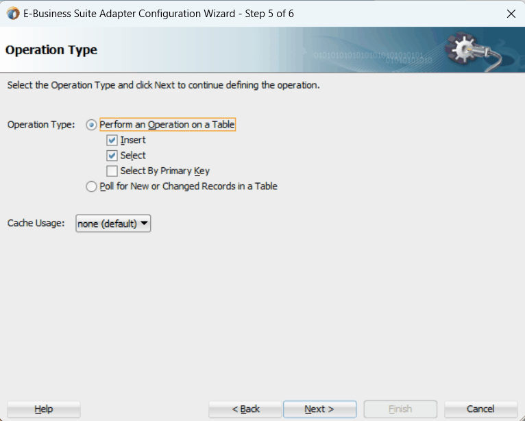
Select the Perform an Operation on a Table radio button and then choose the Select and Insert checkboxes.
Click Next. The Select Table page appears which displays the tables that have been previously imported in this JDeveloper project. Select the OE_HEADER_IFACE_ALL table.
Click Next. The Relationships page is displayed.
Click Next. The Attribute Filtering page appears.
Click Deselect All and select the orderSourceId checkbox only.
The mapped flexfield table column names we defined earlier for both key and descriptive flexfields are already selected in this page. However, they appear as grayed-out attributes indicating that you cannot deselect them.
Click Next. The Define Selection Criteria page is displayed with SQL statements populated.
Click Next. The Advanced Options page is displayed.
Click Next. The JCA Endpoint Properties page is displayed.
Click Next and then click Finish.
The wizard generates the WSDL file corresponding to the partner link. An enhanced XSD file, for example AppsReference_flex.xsd, is also created. This XSD file contains the schema describing the procedure arguments with the elements representing the interface table columns that have been replaced with flexfield segment names.
Click Apply and then OK.
Additionally, configuration file and flexfield mapping file are created. For more information on these files, see Reviewing Flexfield Configurations.
Once a new flexfield mapping has been configured or added, if modification is needed, you can make updates by first selecting desired flexfield type that you want to modify and then make needed changes. For more information on how to modify the selected mapping details, see Modifying Flexfield Mapping Definitions.
Both key and descriptive flexfield mapping data configured earlier during the partner link creation can be shown at design time along with the following activities orchestrated in the BPEL process within in a SOA composite:
A Composite Example with Key and Descriptive Flexfield Mappings
Here is an example describing both key and descriptive flexfield mappings in the BPEL process of a SOA composite:
Create a new SOA composite application with BPEL process
Add a partner link service called AppsReference with the key and descriptive flexfield mappings that we configured earlier for the ONT.OE_HEADERS_IFACE_ALL open interface table.
Add a partner link for File Adapter WriteSelectOutput to write the inserted order data as an output file in XML format.
In the File Directories dialog, enter the physical directory (such as /usr/tmp) where the output xml file (such as output_payload.xml) resides.
In the Messages dialog, select the 'browse for schema file' icon next to the URL field to open the Type Chooser.
Click Type Explorer and select Project Schema Files > AppsReference_table.xsd > AppsReference_flex.xsd > OeHeaderIFaceAllCollection.
Click OK. The selected schema information will be automatically populated in the URL and Schema Element fields.
Configure three Invoke activities
Associate the first Invoke activity with the partner link AppsReference to insert data to the ONT.OE_HEADERS_IFACE_ALL open interface table columns.
Associate the second Invoke activity with the partner link AppsReference that contains flexfield mapping to invoke the service with selected order data. Ensure to click the Output tab to specify the output variable.
Associate the third Invoke activity with the File Adapter partner link WriteSelectOutput to write the output file.
Add two Assign activities:
To pass order data containing both key and descriptive flexfields defined earlier as part of the input payload to the first Invoke activity to invoke the service AppsReference.
Mapped key and descriptive flexfield column names corresponding to the flexfield matching segments defined in the Oracle E-Business Suite are displayed in the Assign activity. See: Assigning Parameters with Key and Descriptive Flexfields in the Assign Activity.
To pass the output details from the service invocation as input data to the File Adapter.
BPEL Process in SOA Composite
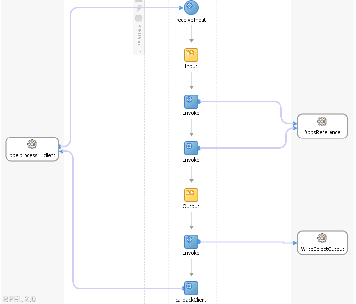
For more information on how to create design time tasks, see Design-Time Tasks for Open Interface Tables.
Flexfield Validation in the Schema File
Select the enhanced XSD file (such as AppsReference_flex.xsd) in Oracle JDeveloper and notice that the mapped key flexfields are displayed with type 'flex' under the Sample_Adapter_KFF, and the mapped descriptive flexfields are displayed with type 'flex' under the FND_FLEX_TEST flexfield as part of the schema.
For key flexfields, the following table explains the relationship between the key flexfield mapping data and the actual segments defined in Oracle E-Business Suite:
| Key Flexfield Segments Mapped During Flexfield Configuration | Key Flexfield Segments Defined in Oracle E-Business Suite |
|---|---|
| SEGMENT1 | BSB_Number |
| SEGMENT2 | Account_Number |
| SEGMENT3 | Account_Name |
Mapped segment column names for the key flexfield 'BSB_Number', 'Account_Number' and 'Account_Name' are displayed in the Oracle E-Business Suite Module Browser once the mapping is complete.
Schema File with Mapped Key Flexfield Segments
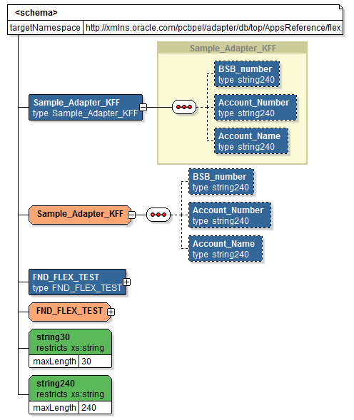
For descriptive flexfields, the mapped table column names Address_Line1, Address_Line2, Address_Line3, Town/City, State, and Pin_Code are grouped by context value IN, and Postal_Code, Province, City, Address_Line1, Address_Line2, and Address_Line3 are grouped by context value JP listed in a tree structure. Context value nodes are connected with the <choice> icon in between indicating that only either one of the context values and its associated table columns can be selected.
Schema File with Mapped Descriptive Flexfield Segments
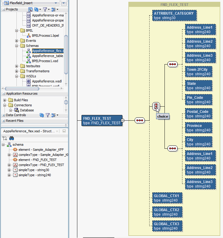
Assigning Parameters with Key and Descriptive Flexfields in the Assign Activity
In the Assign activity of the BPEL process diagram within the SOA composite application, the mapped key and descriptive flexfields can be displayed and used to pass an input variable received from a payload to the Invoke activity for AppsReference service invocation.
In the Assign activity, the mapped key flexfields are displayed under Variables > Process > Variables > Invoke_Insert_InputVariable > OeHeadersIfaceAllCollection > ns4:OeHeadersIfaceAllCollection > ns4:OeHeadersIfaceAll > ns5:Sample_Adapter_KFF.
The mapped descriptive flexfieldd are displayed under Variables > Process > Variables > Invoke_Insert_InputVariable > OeHeadersIfaceAllCollection > ns4:OeHeadersIfaceAllCollection > ns4:OeHeadersIfaceAll > ns5:FND_FLEX_TEST. Expand the <choice> node to locate the segment values based on selected context value, either IN or JP.
The target parameters ns5:ATTRIBUTE1 was mapped to the following descriptive flexfield columns during the descriptive flexfield configuration earlier:
Address_Line1 (under context value <sequence(IN)>)
Postal_Code (under context value <sequence(JP)>)
The target parameters ns5:ATTRIBUTE2 was mapped to the following descriptive flexfield columns during the flexfield configuration earlier:
Address_Line2 (under context value <sequence(IN)>)
Province (under context value <sequence(JP)>)
The target parameters ns5:ATTRIBUTE3 was mapped to the following descriptive flexfield columns during the flexfield configuration earlier:
Address_Line3 (under context value <sequence(IN)>)
City (under context value <sequence(JP)>)
The target parameters ns5:ATTRIBUTE4 was mapped to the following descriptive flexfield columns during the flexfield configuration earlier:
Town/City (under context value <sequence(IN)>)
Address_Line1 (under context value <sequence(JP)>)
The target parameters ns5:ATTRIBUTE5 was mapped to the following descriptive flexfield columns during the flexfield configuration earlier:
State (under context value <sequence(IN)>)
Address_Line2 (under context value <sequence(JP)>)
The target parameters ns5:ATTRIBUTE6 was mapped to the following descriptive flexfield columns during the flexfield configuration earlier:
Pin_Code (under context value <sequence(IN)>)
Address_Line3 (under context value <sequence(JP)>)
Assigning Variables
For the first Assign activity, use the following steps to assign the variables:
In the From navigation tree, navigate to Variables > Process > Variables > inputVariable and select body.
In the To navigation tree, navigate to Variables > Process > Variables > Invoke_Insert_InputVariable and select OeHeadersIfaceAllCollection
Drag the source node (body) to connect to the target node (OeHeadersIfaceAllCollection) that you just specified. This creates a line that connects the source and target nodes. The copy rule is displayed in the From and To sections at the bottom of the Edit Assign dialog box.
For the second Assign activity, use the following steps to assign the variables:
Since the OeHeadersIfaceAllCollection node variables contained in the Source and Target are identical, instead of specifying each flexfield, we can simply drag the source node (OeHeadersIfaceAllCollection) to connect to the target node (OeHeadersIfaceAllCollection) to complete the second Assign activity.
In the From navigation tree, navigate to Variables > Process > Variables > Invoke_AppsReferenceSelect_OutputVariable and select OeHeadersIfaceAllCollection.
In the To navigation tree, navigate to Variables > Process > Variables > Invoke_Write_InputVariable and select body.
Drag the source node (OeHeadersIfaceAllCollection) to connect to the target node (body) that you just specified. This creates a line that connects the source and target nodes. The copy rule is displayed in the From and To sections at the bottom of the Edit Assign dialog box.
Click Apply and OK to complete the Assign activity.
After deploying the BPEL process contained in a SOA Composite application to the Oracle WebLogic managed server (such as 'soa-server1'), the key and descriptive flexfields we configured earlier are displayed in the Oracle Enterprise Manager Fusion Middleware Control (http://<servername>:<portnumber>/em).
Click the Target Navigation icon near the left top corner to display the Target Navigation pane on the left. Expand the Target Navigation tree by clicking SOA > soa-infra (soa-server1) to navigate through the SOA Infrastructure home page and menu to access your deployed SOA composite applications (such as 'Insert [1.0]') running in the SOA Infrastructure for that managed server.
In the Deployed Composites tab, click the SOA Composite application that you want to initiate (such as 'Insert [1.0]') and click Test at the top of the page. The Test Web Service page for initiating an instance appears.
You can specify the XML payload data to use in the Input Arguments section.
Both key and descriptive flexfield mappings defined earlier are displayed as part of the input payload fields.
Displaying Mapped Descriptive Flexfields As Part of the Payload
In the SOAP Body section, expand the Payload > OeHeadersIfaceAll > OeHeadersIfaceAll > FND_FLEX_TEST.
One set of descriptive flexfield configured earlier at the design time are passed as part of the payload input and displayed at the run time.
FND_FLEX_TEST (context value 'IN')
Address_Line1
Address_Line2
Address_Line3
Town/City
State
Pin_Code
Displaying Mapped Key Flexfields As Part of the Payload
In the SOAP Body section, expand the Payload > OeHeadersIfaceAll > OeHeadersIfaceAll > Sample_Adapter_KFF.
Mapped key flexfield (Sample_Adapter_KFF) with the following mapped segments are displayed as part of the input payload fields:
BSB_Number
Account_Number
Account_Name
Enter appropriate data as input payload. Click Invoke to invoke the service
In the Instance ID column, click a specific instance ID to show the message flow through the various service components and binding components. The Flow Trace page is displayed.
Click the Insert BPEL Component link to open the instance details.
In the Audit Trail tab, click the <payload> link under the first Invoke activity. The payload details is displayed.
Go to the directory (such as \user\tmp) where you specified for the write operation when defining the File Adapter. Open the output XML file. The data should be the same as the input details shown in the payload from the first Invoke activity.
The output content is part of a response message for the requestor.
Response Message
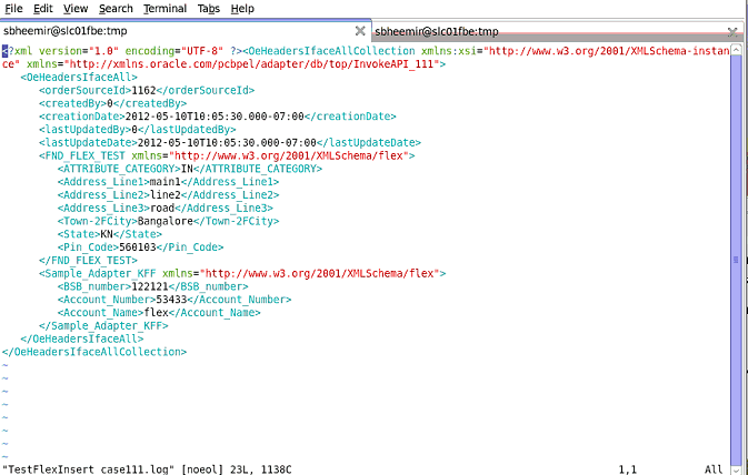
Instead of configuring a new mapping, you can simply import an existing mapping for your selected interface. By using a previously configured mapping, you can quickly establish the flexfield mapping for your interface or use it as a base with proper modification if needed.
To import an existing mapping, click Import from File in the Configure Flexfields region. The Open window appears where you can select a desired flexfield mapping.
Open Window with a Selected Flexfield Mapping
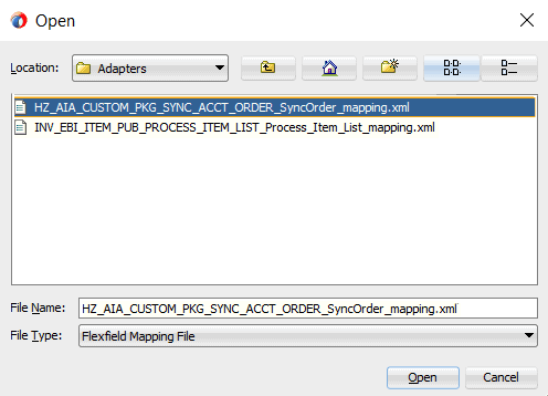
After selecting the desired mapping to be imported, click Open. The selected mapping file is automatically displayed in the Import Flexfield Data into the project field.
For example, select 'HZ_AIA_CUSTOM_PKG_SYNC_ACCT_ORDER_SyncOrder_mapping.xml' file and the imported mapping for the selected API is automatically displayed in the Parameters with Corresponding Flexfield Mappings region along with the selected mapping file name.
When a desired mapping is imported for the selected interface, you will need to select the structure for a key flexfield and context values for a descriptive flexfields.
First, select the key or descriptive flexfield in the Flexfield Definitions section that requires modification, and then click Edit. The Flexfield Subflow - Welcome page is displayed. Click Next to select the desired flexfield context values if it's for a descriptive flexfield.
Flexfield Subflow - Configure Flexfields
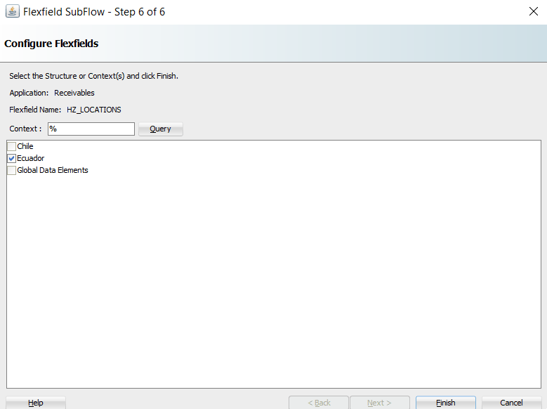
Click Finish to complete the descriptive flexfield mapping information. The updated descriptive flexfield context value (Ecuador) is now added both in the Parameters with Corresponding Flexfield Mappings region and Flexfield Definitions section.
Oracle E-Business Suite Module Browser with Updated Mapping
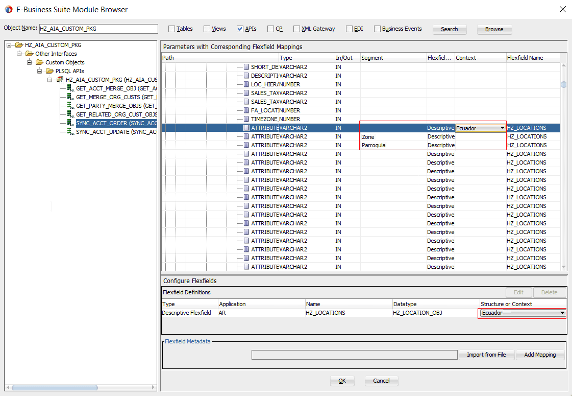
Use the same approach to update the key flexfield that requires structure information before clicking OK.
For more information on how to modify the selected mapping details, see Modifying Flexfield Mapping Definitions.
Oracle E-Business Suite Adapter allows you to modify flexfield mapping definitions for both key and descriptive flexfields as often as needed. However, modification is only limited to context values for a descriptive flexfield or flexfield structure for a key flexfield. If further update is needed in addition to modifying structure or context values, you should delete the flexfield mapping first and configure a new one.
Modifying Flexfield Mapping Data
To modify flexfield mapping data, select either the Key Flexfield or Descriptive Flexfield in the Flexfield Definitions section that you want to modify and then click Edit. Appropriate flexfield pages corresponding to your selected flexfield type appear where you can modify the flexfield mapping details.
For example, modify the structure of the descriptive flexfield (HZ_LOCATIONS). The Configure Flexfields window appears after you click Next in the Flexfield Subflow Welcome wizard.
Flexfield Subflow - Configure Flexfields

Click Query and select the 'Ecuador' checkbox only as the context value. Click Finish to complete the modification. The updated flexfield information should be reflected in the Flexfield Definitions section.
Configure Flexfields Region with Modified Flexfield Mapping Data

You can also validate the changes in the flexfield configuration xml file (<projectname>_flex-config.xml). See: Reviewing Flexfield Mapping Configurations.
For more information on how to configure or add each Flexfield Subflow window, see Adding or Configuring a New Flexfield Mapping.
Deleting Flexfield Mapping Data
To delete flexfield mapping data, select either the Key Flexfield or Descriptive Flexfield that you want to delete and then click Delete. This removes the selected flexfield mapping data and the associated structure or values from the database.
Alternatively, use [Control] and [Shift] keys to select multiple flexfield mappings before the deletion.
After creating a partner link with flexfield mapping information, from Oracle JDeveloper, expand the SOA > Schemas folder and select the enhanced XSD file, for example ProcessItem_KFF_flex.xsd, to validate the flexfield mapping information you configured or updated earlier.
The enhanced schema information is displayed with flexfield segment names based on the mapping chosen at the design time.
An Enhanced XSD File

Additionally, two xml files are created along with the XSD file. Expand the SOA > Adapters folder to view the file details:
Mapping XML: The mapping xml file (for example INV_EBI_ITEM_PUB_PROCESS_ITEM_LIST_ProcessItem_KFF_mapping.xml) would hold the mapping information captured in the mapping wizard panel. This information can be reused for the same API and can be imported from another Partner Link.
Key Flexfield Mapping Details in Oracle JDeveloper
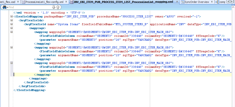
Another mapping example (ONT_OE_HEADERS_IFACE_All_mapping.xml) is for the open interface table we defined earlier. This example contains the mappings for both key and descriptive flexfields:
Key and Descriptive Flexfield Mapping Details in Oracle JDeveloper
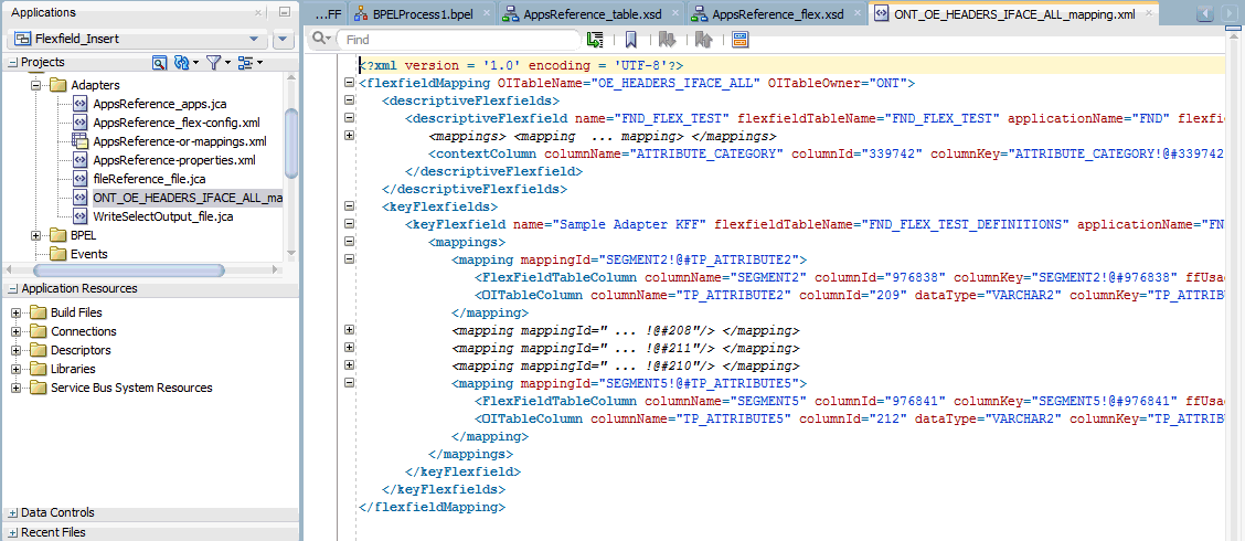
For information on how to import the flexfield mapping for a selected API or open interface table, see Importing an Existing Flexfield Mapping.
Config XML: The config xml (for example OE_ORDER_PUB_PROCESS_LINE_GL_Flexfield_flex-config.xml) has the flexfield information including both key and descriptive flexfield mappings if configured. This is not reusable.
Please note that config xml is internal to the partner link, it should neither be edited nor reused.
Flexfield Configuration Details in Oracle JDeveloper
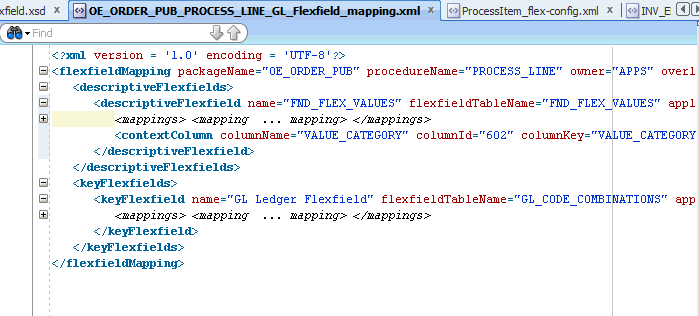
Oracle E-Business Suite Adapter implements the Oracle SOA Suite logging framework to write the diagnostic log files in text format. Therefore, whenever the Oracle E-Business Suite services are invoked using Oracle E-Business Suite Adapter, the log messages are recorded which can be accessed by system administrator. This enriches the problem identification mechanism to track any issues during service invocations at run time for Oracle E-Business Suite Adapter.
Oracle E-Business Suite Adapter and technology adapters implement the LogManager interface of JCA Binding Component, which redirects the log files for both inbound and outbound interactions to the soa-diagnostic.log file in the Oracle Diagnostic Logging (ODL) format. These log files record all types of events including startup and shutdown information, errors and warning messages, access information on HTTP requests, and additional information. It provides a quick, inside-out view about the invocation process which greatly helps administrators identify and resolve potential issues efficiently. With proper log-level configuration in Oracle Enterprise Manager Fusion Middleware Control, you can view ODL level log files written to a single file at run time for Oracle E-Business Suite Adapter as well as technology adapters.
To better understand how the logging mechanism work, the following topics are discussed in this chapter:
For more information about SOA Suite, see Oracle Fusion Middleware Administrator's Guide for Oracle SOA Suite.
All logs of Oracle E-Business Suite Adapter and technology adapters are redirected to the soa-diagnostic.log file in the Oracle Diagnostic Logging (ODL) format. To be able to view logs for Oracle E-Business Suite Adapter, you need to set or enable an appropriate message type and its associated log level for the logger oracle.soa.adapter using the Oracle Enterprise Manager Fusion Middleware Control. This enables the log settings at the Oracle SOA Suite level.
Note: The logger configuration is under $FMWHOME/user_projects/domains/soainfra/config/fmwconfig/servers/soa_server1/logging.xml and the corresponding logger name for all Oracle JCA Adapters is called oracle.soa.adapter.
The following table lists the diagnostic message types and log levels:
Note: For each message type, possible values for message level are from 1 (highest severity) through 32 (lowest severity). Some components support only some of the levels for each message type. Generally, you need to specify only the type; you do not need to specify the level.
The default message type for each logger is set to NOTIFICATION, level 1.
| Message Type | Level | Description |
|---|---|---|
| INCIDENT_ERROR | 1 | A serious problem that may be caused by a bug in the product and that should be reported to Oracle Support. Examples are errors from which you cannot recover or serious problems. |
| ERROR | 1 | A serious problem that requires immediate attention from the administrator and is not caused by a bug in the product. An example is if Oracle Fusion Middleware cannot process a log file, but you can correct the problem by fixing the permissions on the document. |
| WARNING | 1 | A potential problem that should be reviewed by the administrator. |
| NOTIFICATION | 1 | A major lifecycle event such as the activation or deactivation of a primary subcomponent or feature. |
| NOTIFICATION | 16 | A finer level of granularity for reporting normal events. |
| TRACE | 1 | Trace or debug information for events that are meaningful to administrators, such as public API entry or exit points. |
| TRACE | 16 | Detailed trace or debug information that can help Oracle Support diagnose problems with a particular subsystem. |
| TRACE | 32 | Very detailed trace or debug information that can help Oracle Support diagnose problems with a particular subsystem. |
To set the diagnostic message type and log level for Oracle E-Business Suite Adapter in Oracle SOA Suite:
Use the following procedures to set the message type and its associated log level:
Navigate to http://<servername>:<portnumber>/em.
The Oracle Enterprise Manager Fusion Middleware Control home page is displayed.
Enter username and password to log on to the console.
Right-click soa-infra from the SOA Folder in the Navigator tree.
Select Logs > Log Configuration from the pop-up menu.
Note: You can also access the Log Configuration page by clicking the SOA Infrastructure Menu and selecting Logs > Log Configuration from the drop-down menu.
This opens the Log Configuration page where you can view a list of loggers (persistent or active run time) and configure the Oracle Diagnostic Logging (ODL) level for setting the amount and type of information to write to a log file and the log level state.
Select the Log Levels tab.
Select one of the following values from the View drop-down list:
Runtime Loggers (default): Runtime loggers are automatically created during run time and become active when services are getting executed. For example, oracle.soa.b2b or oracle.soa.bpel are runtime loggers. Log levels for runtime loggers are not persistent across component restarts.
Loggers with Persistent Log Level State: Persistent loggers are loggers that are saved in a configuration file and become active when the component is started. The log levels for these loggers are persistent across component restarts.
Note: By default, the log level is set for Runtime Loggers. Runtime loggers do not persistent across when a component restarts. To ensure that log levels persist across component when it restarts, select Loggers With Persistent Log Level State from the View list.
Expand the oracle.soa node to locate oracle.soa.adapter runtime logger in the Logger Name list. Select the logging level from the Oracle Diagnostic Log Level drop-down list. For example, select 'TRACE:32 (FINEST)'.
Click Apply.
Creating and Editing Log File in the Log Files Tab
You can edit a specific log file by clicking the log handler link displayed in the Log File column. This opens the Log Files tab where you can configure the basic and advanced log configuration settings. These settings include handler's name, the log file in which the log messages are logged, the format of the log messages, the rotation policies used, and other parameters based on the log file configuration class.
For example, select the log handler from the table and click Edit Configuration. The Edit Log File dialog box is displayed.
To change log file location, enter a new path in the Log Path field.
To configure message levels, select the logging level from the Log Level drop-down list. For example, select 'TRACE:32 (FINEST)'.
To configure log file rotation, in the Rotation Policy section, select either Size Based or Time Based log file with appropriate information.
Fore more information on how to configure log file, see the Managing Log Files and Diagnostic Data Chapter, Oracle Fusion Middleware Administrator's Guide.
For more information about SOA Suite, see Oracle Fusion Middleware Administrator's Guide for Oracle SOA Suite.
Based on the log level set for oracle.soa.adapter runtime logger in Oracle SOA Suite, logging can be automatically controlled or enabled for PL/SQL APIs and Concurrent Programs while these interfaces are invoked during runtime execution. There is no need to enable the FND logging framework on the Oracle E-Business Suite side separately.
Note: This automatic FND logging would be available in Oracle E-Business Suite Release 12.1.3 and above only.
The following table lists the log level mapping between oracle.soa.adapter runtime logger and the corresponding Oracle E-Business Suite:
| Runtime Logger oracle.soa.adapter Log Level | Oracle E-Business Suite Log Level |
|---|---|
| INCIDENT_ERROR | LEVEL_UNEXPECTED |
| ERROR | LEVEL_ERROR |
| WARNING | LEVEL_EXCEPTION |
| NOTIFICATION 1, 16, 32 | LEVEL_EVENT |
| TRACE 1 | LEVEL_PROCEDURE |
| TRACE 16, 32 | LEVEL_STATEMENT |
Oracle E-Business Suite Adapter and technology adapters implement the LogManager interface of JCA Binding Component, which redirects the log files written to a single file at run time in the Oracle Diagnostic Logging (ODL) format.
For both outbound and inbound interactions, the log files are redirected to the single file soa-diagnostic.log.
The log files for Oracle SOA Suite that is deployed to the server-soa managed server are located in MW_HOME/user_projects/domains/<domain_name>/servers/server-soa/logs/soa-diagnostic.log.
To search and view Oracle E-Business Suite Adapter log files, you can use Oracle Enterprise Manager Fusion Middleware Control, the WLST displayLogs command-line tool, or you can download log files to your local client and view them using another tool (for example a text editor, or another file viewing utility). For information on how to use WLST command-line tool to search and view log files, see the Managing Log Files and Diagnostic Data Chapter, Oracle Fusion Middleware Administrator's Guide.
Use the following steps to search Adapter Logs through the Oracle Enterprise Manager Fusion Middleware Control:
Navigate to http://<servername>:<portnumber>/em.
The Oracle Enterprise Manager Fusion Middleware Control home page is displayed.
Enter username and password to log on to the console.
There are two ways to access the Log Messages page from the Navigator tree in the left pane:
From the SOA folder, right-click soa-infra.
From the WebLogic Domain folder, right-click soainfra.
Select Logs and then View Log Messages from the pop-up menu. The Log Messages page is displayed with the Search section and a table that shows a summary of the messages with default search criteria.
Enter the following search criteria for searching the log messages for Oracle E-Business Suite Adapter:
Date Range: Select your value from the drop-down list and enter an appropriate number. For example, 'Most Recent' 6 hours.
If 'Time Interval' is selected from the drop-down list, select the calendar icon for Start Date and then select the date and time. Similarly, select the calendar icon for End Date and then select the date and time.
Message Types: Select one or more of the message types. For example, select the Trace checkbox if it is the message type configured earlier for Oracle E-Business Suite Adapter.
Message: Select 'Contains' from the list of values and then enter 'Oracle E-Business Suite Adapter' in the text box.
Specify more search criteria if needed in the Search section.
You can optionally add more search criteria by clicking Add Fields. This action allows you to add more criteria, such as Host, which lets you narrow the search to particular hosts. Then click Add.
Execute the search by clicking Search. All messages that match your search criteria will be retrieved and displayed in the table. These messages can be displayed as messages, or can be grouped by message type or message ID depending on the selected value in the Show field.
Click one of the log messages from the table. The selected message details, such as message level, component, ECID (Execution Context ID), Relationship ID, actual message, are displayed below the table of messages.
Clicking the ECID link retrieves related messages with the same ECID in the Related Messages by ECID page. For more information on related messages, see Correlating Messages Across Log Files and Components.
Select an appropriate output option from the Export Messages to File drop-down list if you want to export log messages as a Oracle Diagnostic Log Text file (.txt) XML file (.xml), or Comma-Separated List (.csv) file.
Click Target Log Files to open the Log Files page where you can view a list of log files related to the managed server (server-soa).
Select a file and click View Log File. The View Log File page is displayed for the selected log file where you can view a list of messages contained in this log.
To view the details of a message, select the message. The message details, such as message level, component, ECID, Relationship ID, actual message, are displayed below the table of messages.
To view messages that are related by time or ECID, click View Related Messages and select 'by Time' or by 'ECID (Execution Context ID)'.
Alternatively, clicking the ECID link directly from the message details also retrieves related messages with the same ECID in the Related Messages by ECID page.
Oracle Fusion Middleware components provide message correlation information for diagnostic messages. Message correlation information helps those viewing diagnostic messages to determine relationships between messages across components. Each diagnostic message contains an Execution Context ID (ECID) and a Relationship ID.
An ECID is a globally unique identifier associated with the execution of a particular request. An ECID is generated when the request is first processed. A Relationship ID distinguishes the work done in one thread on one process from the work done by any other threads on this and other processes on behalf of the same request.
While viewing log messages in the Oracle Enterprise Manager Fusion Middleware Control, you can view correlated messages by selecting a log message first, and then selecting one of the following values from the View Related Messages drop-down list:
Note: The View Related Messages selection is available only when 'Messages' is chosen in the Show field when displaying all matching messages based on search criteria. If 'Group by Message Type' or 'Group by Message ID' is selected in the Show field, then all matching messages are displayed by groups based on message type or message ID. In this situation, the View Related Messages field is not available.
by Time: This displays the Related Messages by Time page where all messages with the same timestamp as the selected message are displayed in this page.
by ECID (Execution Context ID): This displays the Related Messages by ECID page where all messages with the same ECID as the selected message are displayed in this page.
By searching for related messages using the message correlation information, multiple messages can be examined and the component that first generates a problem can be identified. Message correlation data can help establish a clear path for diagnosing errors generated in the API being invoked.
In order to identify the root cause of an issue or error which might occur during invocation of an Oracle E-Business Suite interface, Oracle E-Business Suite Adapter provides user-friendly, descriptive exceptions and error messages. Especially, these would be available during invocation of any PL/SQL APIs.
Apart from handling errors during adapter preprocessing and the runtime execution by Database Adapter and AQ Adapter, it also provides a way to retrieve the functional errors raised by PL/SQL APIs at run time, without the need for an extra call to retrieve them. These messages would guide you to pinpoint the cause of failures at run time.
Additionally, based on the common logging framework used by other JCA Adapters, all errors and exceptions pertaining to Oracle E-Business Suite Adapter and debug information will be logged. This allows administrators or developers to better understand what happened during the execution and take necessary actions to solve the issue.
During the invocation of an integrated interface supported by Oracle E-Business Suite Adapter, in case of issues or errors occurred (such as the entered order number does not exist while invoking OE_ORDER_PUB.CHANGE_ORDER API), an exception (ORA-20100: Order number does not exist) would be thrown and such exception consists of functional errors. This type of exception is used extensively to report functional problems while executing the API.
For most PL/SQL APIs, functional errors can be thrown as SQLException caught by Adapter runtime engine along with code and message or as part of API output parameters. However, certain PL/SQL APIs do not throw functional errors during execution, but they keep on accumulating them in the memory stack. The responsibility of fetching the errors is deferred to the caller of the APIs.
For example, HRMS APIs put functional errors in FND_MESSAGE stack using FND_MSG_PUB.put package. Upon completion of the API call, the caller must explicitly fetch the errors from this stack using FND_MSG_PUB.GET() methods.
Note: Error messages can only be retrieved from the stack FND_MSG_PUB in this release.
For such APIs that require explicit handling, a new JCA property called APIErrorHandler is introduced to fetch functional errors from the FND_MESSAGE memory stack.
At run time, if the JCA property is set, the error handler will be invoked right after the execution of the PL/SQL API. If this returns one or more errors, then Oracle E-Business Suite Adapter will throw runtime exception. The exception handler, such as catchAll fault handler, can be used to process the messages coming out of this function.
Please note that the following functional error handling parameter needs to be added to the WSDL file (XX_apps.jca) for fetching the functional errors for such APIs:
<property name="APIErrorHandler" value="FND_MSG_PUB.GET_DETAIL"/>
SOA Composite Application with BPEL Process Scenario
This example uses a PL/SQL API called Create Project (PA_PROJECT_PUB.CREATE_PROJECT) to explain how to use the APIErrorHandler JCA property along with the catchAll fault handler to catch any faults which might occur during the service invocation.
At run time, if the service invocation is executed successfully, a project should be created in Oracle Projects by using an existing project. If any error occurs, the catchAll fault handler will catch the error messages. These messages will be written in an xml file.
Functional Requirement
To successfully create a project in Oracle Project using the PL/SQL API (PA_PROJECT_PUB.CREATE_PROJECT), the following functional requirement must be in place:
An existing project is associated with a template in Oracle Project.
A valid Oracle E-Business Suite user who has the responsibility to create a project in Oracle Project, and that user must have the privilege to execute this PA_PROJECT_PUB.CREATE_PROJECT API.
This example includes the following design-time activities:
Create a main process to invoke the Create Project service through a partner link
Create a partner link for the Create Project API
Add an Invoke activity to invoke the API
Add an Assign activity to assign the input for the service invocation
Add another Assign activity to assign the output for the service invocation
Add a CatchAll process on the main process you just created to catch faults if occur during the service invocation
Create a file adapter with "Write File" as the operation type
Add an Assign activity to pass the faults from the catchAll fault handler
Add an Invoke activity to invoke the file adapter partner link to write the error messages in an xml file
SOA Composite Application with BPEL Process Creation Flow
Based on the process scenario, the following design-time tasks are explained in this section:
Deploying and Testing the Composite Application
Once you complete the design-time activities, deploy the composite application and test it to see if the output file generated by the file adapter contains the faults.
See Validating and Testing SOA Composite Application with BPEL Process.
For the payload information on creating a project, see Sample Payload for Creating a Project.
Use this step to create a new SOA composite application that will contain various BPEL process activities.
To create a new SOA composite application with BPEL process:
Open Oracle JDeveloper.
Click New Application in the Application Navigator.
The "Create SOA Application - Name your application" page is displayed.
Enter an appropriate name for the application in the Application Name field and select SOA Application from the Application Template list.
Click Next. The "Create SOA Application - Name your project" page is displayed.
Enter an appropriate name for the project in the Project Name field, for example, TestProjectCreation.
In the Project Technologies tab, select 'Web Services' and ensure that SOA is selected from the Available technology list to the Selected technology list.
Click Next. The "Create SOA Application - Configure SOA settings" page is displayed.
Select Composite With BPEL from the Composite Template list, and then click Finish. You have created a new application, and a SOA project. This automatically creates a SOA composite.
In the Create BPEL Process page, leave the default BPEL 2.0 Specification selection unchanged. This creates a BPEL project that supports the BPEL 2.0 specification.
Name: Enter an appropriate name for the BPEL process, such as TestProjectCreation.
Template Type: Select "Web Service".
Template: Select Synchronous BPEL Process.
Select 'required' from the Transaction drop-down list and click OK. A synchronous BPEL process is created with the Receive and Reply activities. The required source files including bpel and wsdl, using the name you specified and the associated composite are also generated.
Use this step to create a partner link called CreateProjectApi for the PL/SQL API that will be invoked later.
To create a partner link:
Drag and drop Oracle Applications from the BPEL Services list into the right Partner Link swim lane of the process diagram. The Adapter Configuration Wizard Welcome page appears. Click Next.
The Adapter Configuration Wizard Welcome page appears.
Enter a service name in the Service Name field. For example, CreateProjectApi. Click Next. The Service Connection dialog appears.
Specify your database connection and proceed to the Oracle Applications Module Browser.
Locate the PL/SQL API in the Oracle Applications Module Browser by navigating to Projects Suite (PJ_PF) > Projects (PA) > Project (PA_PROJECT) > PLSQL > Project Definition (PA_PROJECT_PUB) to select Create Project (PA_PROJECT_PUB.CREATE_PROJECT).
For information about Oracle Applications Module Browser, see Understanding the Oracle Applications Module Browser.
In the Application Interface page, click Next.
In the Finish page, click Finish to complete the process of configuring Oracle E-Business Suite Adapter.
The wizard generates the CreateProjectApi.wsdl file corresponding to the CreateProjectApi_sp.xsd schema. This WSDL file is now available for the partner link.
Select the Partner Link Type and Partner Role fields from the drop-down lists. Click Apply and then OK to complete the partner link configuration.
To fetch the functional errors for the API you just created as a partner link:
In Oracle JDeveloper, navigate to SOA > Adapters folder and double click the CreateProjectApi_apps.jca. Add the following functional error handling parameter to the CreateProjectApi_apps.jca file and save the changes:
<property name="APIErrorHandler" value="FND_MSG_PUB.GET_DETAIL"/>
CreateProjectApi_apps.jca File with Functional Error Handling Parameter Highlighted
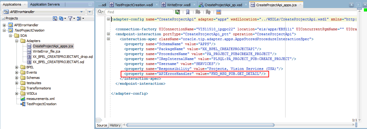
Use this step to configure a BPEL process by writing the output to a text file.
In Oracle JDeveloper, drag and drop the File Adapter service from the BPEL Services list into the right Partner Link swim lane of the process diagram. The Adapter Configuration wizard welcome page appears.
Click Next. The Service Name dialog box appears.
Enter a name for the file adapter service, for example WriteError.
Click Next. The Adapter Interface dialog box appears.
Select the Define from operation and schema (specified later) radio button and click Next. The Operation dialog box appears.
Specify the operation type, for example Write File.
This automatically populates the Operation Name field.
Click Next to access the File Directories dialog box.
For the Directory specified as field, select Physical Path. Enter directory path, such as /usr/tmp/, in the Directory for Outgoing Files field. Specify a naming convention for the output file, such as pa_%SEQ%_%yyMMddHHmmss%.xml.
Click Next. The Messages dialog box appears.
Select Browse for schema file in front of the URL field. The Type Chooser window is displayed.
Click the Import Schema Files button on the top right corner of the Type Chooser window.
Click the Browse Resources button in the Import Schema File window to add the Error.xsd file to the schema. Select the Copy to Project checkbox. Click OK.
Select the Maintain original directory structure for imported files Copy Options checkbox and click OK.
The selected Error.xsd is displayed as URL and the Exception element is selected as Schema Element.
Click Next and then Finish. The wizard generates the WSDL file corresponding to the partner link. The main Create Partner Link dialog box appears, specifying the new WSDL file WriteError.wsdl.
Click Apply and then OK to complete the configuration and create the partner link with the required WSDL settings for the File Adapter Service.
The WriteError Partner Link appears in the BPEL process diagram.
This step adds a CatchAll activity to catch any faults if occur during the invocation process.
In the expanded Scope activity of the Oracle JDeveloper, click the Add CatchAll icon.
BPEL Diagram with the Add CatchAll Icon Selected
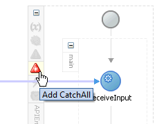
You can find that a CatchAll activity is created in the right side of the main scope activity.
BPEL Diagram with the CatchAll Activity Added
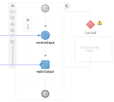
This step is to configure two Invoke activities in order to:
Invoke the CreateProjectApi partner link service.
Invoke the WriteError file adapter partner link that in turn writes the error messages in a output file.
To add an Invoke activity for CreateProjectApi Partner Link:
In Oracle JDeveloper, expand the BPEL Constructs from the Component Palette. Drag and drop the Invoke activity from the Component Palette into the center swim lane of the process diagram, between the receiveInput and replyOutput activities.
Link the Invoke activity to the CreateProjectApi service. The Edit Invoke dialog box appears.
Enter a name for the Invoke activity, such as InvokeCreateProjectAPI.
In the Input tab, click the Create icon next to the Input Variable field to create a new variable. The Create Variable dialog box appears.
Enter a name for the variable. You can also accept the default name. Ensure the Global Variable radio button is selected and click OK.
Select the Output tab. Use the same method mentioned in step 4 to create an output variable.
Click Apply in the Edit Invoke dialog box.
Click OK in the Edit Invoke dialog box to finish configuring the Invoke activity.
The Invoke activity appears in the process diagram.
To add the second Invoke activity for WriteError File Adapter Partner Link:
In Oracle JDeveloper, expand the BPEL Constructs from the Component Palette. Drag and drop the second Invoke activity from the Component Palette into the center swim lane of the CatchAll process diagram.
Link the Invoke activity to the WriteError service. The Edit Invoke dialog box appears.
Follow the instructions described in step 4 of the first Invoke activity to create the input variable for this Invoke activity.
Click Apply and then OK in the Edit Invoke dialog box to finish configuring the Invoke activity.
The second Invoke activity appears in the process diagram.
This step is to configure three Assign activities:
To pass the input information to the CreateProjectApi service through the Invoke activity.
To pass the output information from the CreateProjectApi service through the Invoke activity.
To pass the faults caught through the CatchAll activity as the input to the WriteError file adapter.
To add the first Assign activity in the main scope:
In Oracle JDeveloper, expand the BPEL Constructs from the Component Palette. Drag and drop the Assign activity into the center swim lane of the process diagram, between the receiveInput and Invoke activities.
Double-click the Assign activity to access the Edit Assign dialog box.
Click the General tab to enter the name for the Assign activity, such as 'AssignInput'.
Select the Copy Rules tab and expand the source and target trees:
In the From navigation tree, navigate to Variables > Process > Variables > inputVariable and select payload.
In the To navigation tree, navigate to Variables > Process > Variables > CreateProjectApi_InputVariable and select InputParameters.
Drag the source node (payload) to connect to the target node (InputParameters) that you just identified. This creates a line that connects the source and target nodes. The copy rule is displayed in the From and To sections at the bottom of the Edit Assign dialog box.
The Edit Assign dialog box appears.
Click Apply and then OK to complete the configuration of the Assign activity.
To add the second Assign activity:
Add the second Assign activity by dragging and dropping the Assign activity from the BPEL Constracts section of the Component Palette into the center swim lane of the process diagram, between the Invoke and replyOutput activities.
Repeat Step 2 to Step 3 described in creating the first Assign activity to add the second Assign activity called 'AssignOuput'.
Select the Copy Rules tab and expand the source and target trees:
In the From navigation tree, navigate to Variables > Process > Variables > CreateProjectApi_OutputVariable and select OutputParameters.
In the To navigation tree, navigate to Variables > Process > Variables > outputVariable and select payload.
Drag the source node (OutputParameters) to connect to the target node (payload) that you just identified. This creates a line that connects the source and target nodes. The copy rule is displayed in the From and To sections at the bottom of the Edit Assign dialog box.
Click Apply and then OK to complete the configuration of the Assign activity.
To add the third Assign activity in the CatchAll activity:
Add the third Assign activity by dragging and dropping the Assign activity from the BPEL Constracts section of the Component Palette into the CatchAll process diagram, before the Invoke activity.
Repeat Step 2 to Step 3 described in creating the first Assign activity to add the second Assign activity.
In the Edit Assign dialog, enter the first parameter:
Click the Expression icon to invoke the Expression Builder dialog.
Expression Builder Dialog
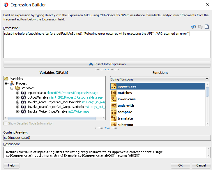
Enter substring-before(substring-after(ora:getFaultAsString(),"Following error occurred while executing the API"),"API returned an error") in the Expression box. Click OK.
The Expression icon with the expression value appears in the center of the Edit Assign dialog, between the From and To navigation tree nodes.
In the To navigation tree, navigate to Variables > Process > Variables > Invoke_Write_Exception_InputVariable > body > ns4:Exception and select ns4: message string.
Drag the Expression icon to connect to the target node (ns4: message string) that you just identified. This creates a line that connects the source and target nodes. The copy rule is displayed in the From and To sections at the bottom of the Edit Assign dialog box.
Edit Assign Dialog
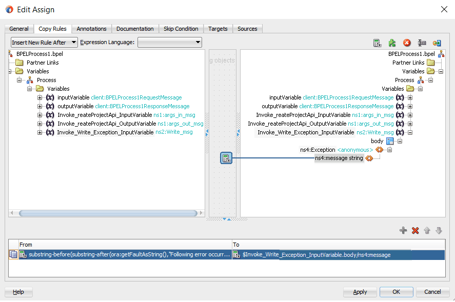
Click Apply and then OK to complete the configuration of the Assign activity.
Complete BPEL Process Flow
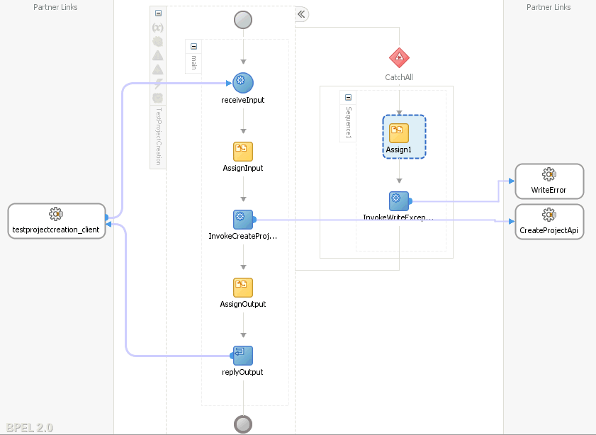
Click the TestProjectCreation to display the Oracle JDeveloper composite diagram:
Composite Diagram

Deploying the SOA Composite Application with BPEL Process
After creating the BPEL process contained in the SOA Composite application at the design time, you need to deploy the SOA Composite with BPEL process first and then manually test the process in the Oracle Enterprise Manager Fusion Middleware Control (http://<servername>:<portnumber>/em).
Important: Before deploying the SOA Composite with BPEL process using Oracle JDeveloper, you must have established the connectivity between the design-time environment and the runtime server. Ensure that you have configured Oracle E-Business Adapter on your Oracle SOA Suite server to handle the service invocation. For configuration details, see:
To deploy the SOA Composite application, in Oracle JDeveloper select the SOA Composite project in the Applications window. Right-click the project name, such as TestProjectCreation, and then select Deploy > [project name] > [serverConnection] from the menu that appears.
For example, you can select Deploy > TestProjectCreation > soa-server1 if you have the server connection set up properly.
In the Select Server page, select 'soa-server1' that you have established the server connection earlier. Click Next.
In the SOA Servers page, accept the default target SOA Server ('soa-server1') selection.
Click Next and Finish to start the deployment process.
You can check for successful compilation in the SOA - Log window, and verify that the deployment is successful in the Deployment - Log window.
Validating and Testing the Deployed SOA Composite
In the Oracle Enterprise Manager Fusion Middleware Control, click the Target Navigation icon near the left top corner to display the Target Navigation pane on the left. Expand the Target Navigation tree by clicking SOA >soa-infra (soa_server1) to navigate through the SOA Infrastructure home page and menu to access your deployed SOA composite applications running in the SOA Infrastructure for that managed server.
In the Deployed Composites tab, click the SOA Composite application that you want to initiate. The selected composite details including the associated component name, services, and references are shown in the Dashboard tab. Click Test at the top of the page.
In the Test Web Service page, specify the XML payload data to use in the Input Arguments section. Enter the input string required by the process and click Test Web Service to initiate the process.
The test results appear in the Response tab upon completion.
In the Response tab, click Launch Flow Trace. Click the Flow Instances tab. In the Search Options dialog, select desired search criteria and click Search. From the Search Results page, click the desired Flow ID to display the Flow Trace page.
If any error occurred during the test, you should find it in the Faults tab.
Click the TestProjectCreation link in the Trace section to view the invocation details in the Audit Trail tab.
Click the Flow tab to check the BPEL process flow diagram. Click an activity of the process diagram to view the activity details and flow of the payload through the process.
For example, click the "InvokeCreateProjectAPI (faulted)" to view the faults.
BINDING.JCA-12563
Exception occurred when binding was invoked.
Exception occurred during invocation of JCA binding: "JCA Binding execute of Reference operation 'CreateProjectApi' failed due to: API  Execution Error.
Following error occurred while executing the API  "PA_PROJECT_PUB.CREATE_PROJECT": "1. PAPA_FUNCTION_SECURITY_ENFORCEDNFND_ERROR_LOCATION_FIELDNFND_MESSAGE_TYPEE
".
API returned an error.
Correct the inputs for the API call. Contact oracle support if error is not fixable.
".
The invoked JCA adapter raised a resource exception.
Please examine the above error message carefully to determine a resolution.
Additionally, verify the faults collected through the file adapter partner link during the service invocation. For example, go to the outputDir (/usr/tmp/) you specified for the write operation during the file adapter partner link creation. Open the output file (such as pa_%SEQ%_%yyMMddHHmmss%.xml) which contains the following faults:
<part name="detail">
<detail>API  Execution Error.
Following error occurred while executing the API  "PA_PROJECT_PUB.CREATE_PROJECT": “
1. PA PA_FUNCTION_SECURITY_ENFORCED N
FND_ERROR_LOCATION_FIELD
FND_MESSAGE_TYPE E".
API returned an error.
Correct the inputs for the API call. Contact oracle support if error is not fixable.
</detail>
</part>
<part name="code">
<code>EBzA-201</code>
</part>
The following information shows the sample payload in creating a project in Oracle E-Business Suite:
<soap:Envelope xmlns:soap="http://schemas.xmlsoap.org/soap/envelope/">
   <soap:Body>
			<ns1:InputParameters xmlns:ns1="http://xmlns.oracle.com/pcbpel/adapter/db/sp/EBSReference">
				<ns1:P_API_VERSION_NUMBER>1.0</ns1:P_API_VERSION_NUMBER>
				<ns1:P_COMMIT>F</ns1:P_COMMIT>
				<ns1:P_INIT_MSG_LIST>T</ns1:P_INIT_MSG_LIST>
				<ns1:P_PM_PRODUCT_CODE>MSPROJECT</ns1:P_PM_PRODUCT_CODE>
				<ns1:P_PROJECT_IN>
					<ns1:PM_PROJECT_REFERENCE>AGL-AMG Project 6</ns1:PM_PROJECT_REFERENCE>
					<ns1:PROJECT_NAME>AGL-AMG Project 6</ns1:PROJECT_NAME>
					<ns1:PA_PROJECT_NUMBER>SAGIR-P6</ns1:PA_PROJECT_NUMBER>
					<ns1:CREATED_FROM_PROJECT_ID>1005</ns1:CREATED_FROM_PROJECT_ID>
					<ns1:CARRYING_OUT_ORGANIZATION_ID>478</ns1:CARRYING_OUT_ORGANIZATION_ID>
					<ns1:PROJECT_STATUS_CODE>ACTIVE</ns1:PROJECT_STATUS_CODE>
					<ns1:DESCRIPTION>TaskDesc</ns1:DESCRIPTION>
					<ns1:START_DATE>2014-01-01T00:00:00</ns1:START_DATE>
					<ns1:COMPLETION_DATE>2018-12-31T00:00:00</ns1:COMPLETION_DATE>
					<ns1:PROJECT_RELATIONSHIP_CODE>Primary</ns1:PROJECT_RELATIONSHIP_CODE>
				</ns1:P_PROJECT_IN>
				<ns1:P_KEY_MEMBERS>
					<ns1:P_KEY_MEMBERS_ITEM>
						<ns1:PERSON_ID>2960</ns1:PERSON_ID>
						<ns1:PROJECT_ROLE_TYPE>PROJECT MANAGER</ns1:PROJECT_ROLE_TYPE>
					</ns1:P_KEY_MEMBERS_ITEM>
				</ns1:P_KEY_MEMBERS>
				<ns1:P_CLASS_CATEGORIES>
					<ns1:P_CLASS_CATEGORIES_ITEM>
						<ns1:CLASS_CATEGORY>Construction</ns1:CLASS_CATEGORY>
						<ns1:CLASS_CODE>New Building</ns1:CLASS_CODE>
					</ns1:P_CLASS_CATEGORIES_ITEM>
				<ns1:P_CLASS_CATEGORIES>
				<ns1:P_TASKS_IN>
					<ns1:P_TASKS_IN_ITEM>
						<ns1:PM_TASK_REFERENCE>1</ns1:PM_TASK_REFERENCE>
						<ns1:PA_TASK_NUMBER>1</ns1:PA_TASK_NUMBER>
						<ns1:TASK_DESCRIPTION>Plant function</ns1:TASK_DESCRIPTION>
						<ns1:PM_PARENT_TASK_REFERENCE></ns1:PM_PARENT_TASK_REFERENCE>
					</ns1:P_TASKS_IN_ITEM>
				   <ns1:P_TASKS_IN_ITEM>
						<ns1:PM_TASK_REFERENCE>1.1</ns1:PM_TASK_REFERENCE>
						<ns1:PA_TASK_NUMBER>1.1</ns1:PA_TASK_NUMBER>
						<ns1:TASK_DESCRIPTION>Plant function</ns1:TASK_DESCRIPTION>
						<ns1:PM_PARENT_TASK_REFERENCE>1</ns1:PM_PARENT_TASK_REFERENCE>
					</ns1:P_TASKS_IN_ITEM>
				</ns1:P_TASKS_IN>
			 <ns1:P_ORG_ROLES/>
			 <ns1:P_STRUCTURE_IN/>
			 <ns1:P_EXT_ATTR_TBL_IN/>
			</ns1:InputParameters>
	</soap:Body>
</soap:Envelope>By implementing the J2EE Data Source for secured connection between Oracle E-Business Suite and Oracle SOA Suite, two distinct advantages can be leveraged. Firstly, to get the secured connection to the Oracle E-Business Suite's application database, you do not require Apps/Apps-equivalent schema's user name and password, just FND user name and password (concept of Oracle E-Business Suite user name and password) is sufficient. Secondly, since the password is not stored in the middleware, not only this eliminates the security risk, but also does away the need to keep the password in-sync between Oracle E-Business Suite and SOA Suite.
Oracle E-Business Suite Adapter authenticates users at run time and gets the connection to Oracle E-Business Suite databases through the use of J2EE data sources. This approach is native to Oracle E-Business Suite in defining the connection pool to access the application database.
Account details information including application login user name and password that was required as part of the configuration for database connection is added together with the dbc file location as input parameters during the J2EE data source creation.
To accomplish this process, the following steps are used to define J2EE data source connection to the Oracle E-Business Suite database:
Register your Service-Oriented Architecture (SOA) suite application tier node on the Oracle E-Business Suite environment and generate the dbc file used by the data source implementation to instantiate the connections.
Copy the dbc file to the application tier server where your SOA suite server runs, and place it on a location in the file system to which the SOA suite owner has access.
Create a connection pool where you need to enter the application login user name, password, and dbc file location as the connection factory properties.
Create an application data source. This is the step that you associate the application data source with the Java Naming and Directory Interface (JNDI) name for the application database connection for Oracle E-Business Suite Adapter.
To enable the native Oracle E-Business Suite connectivity using J2EE data sources feature,