5 Field Replaceable Units

This chapter describes the components of an E5-APP-B card that can be replaced in the field and includes procedures for replacing each type of field replaceable unit (FRU).

5.1 Introduction

E5-APP-B cards are complete application server platforms and are designed for the high-availability environments required by telephony networks. They are installed in an EAGLE shelf.

Even with the advanced reliability of the E5-APP-B design, hardware failures may still occur. The E5-APP-B card is designed for easy maintenance when replacements are needed.

This chapter highlights the E5-APP-B card components that are field replaceable units (FRU) and provides procedures for replacing them.

This chapter explains how to remove a card from the EAGLE. The procedures include the administrative commands required to take a card out of service and place it back into service.

In the event a numbered event message is encountered, refer to the appropriate procedure in Unsolicited Alarm and Information Messages Reference.

Additional information about each command can be found in Commands User's Guide.

5.2 Safety Information

Safety icons and text are used throughout this manual to warn the reader of the potential of personal injury, service interruption, and equipment damage.

Before beginning any procedure described in this manual, make sure that you are familiar with each of the following safety admonishments. Additional safety admonishments may be included, or repeated, for specific procedures.

Caution:

All personnel associated with the installation of these systems must adhere to all safety precautions and use required protection equipment, to avoid the possibility of injury to personnel, service degradation, and/or service interruption.

Caution:

Always wear a wrist strap or other electrostatic protection when handling an E5-APP-B card.

Caution:

Always place removed cards into an electrostatic protection bag before sending to Oracle or storing in inventory (unless the card is being stored in the optional spare card storage shelf).

5.3 E5-APP-B Card FRUs and Part Numbers

The following E5-APP-B card components can be replaced in the field:

  • E5-APP-B cards (P/N 870-3096-01 and P/N 870-3096-02)
  • Drive modules (P/N 870-3097-01 and P/N 870-3097-02)

5.4 Removing and Replacing E5-APP-B Cards

This section gives procedures on removing and replacing the E5-APP-B card and drive modules.

5.4.1 Removing an E5-APP-B Card

Procedure - Remove E5-APP-B card

Note:

The shutdown, init 6 or halt commands will not shut down the E5-APP-B card.
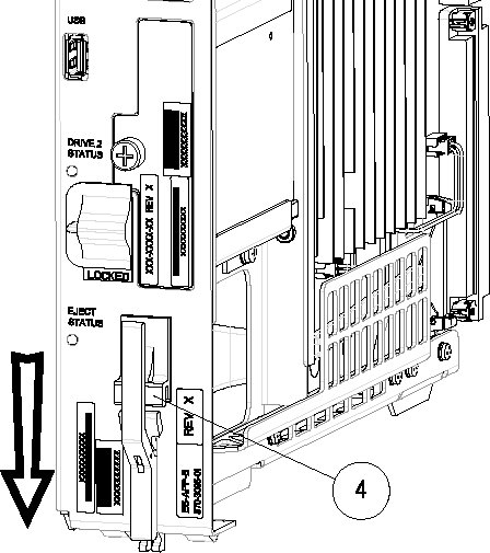
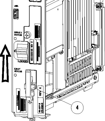
  1. On the E5-APP-B card, slide the Ejector switch (4) up to the UNLOCKED position (see Figure 5-1).

    Caution:

    When the Ejector switch goes from locked to unlocked and the E5-APP-B card is in service, the card will halt.

    Figure 5-1 E5-APP-B Card Eject Hardware Switch, UNLOCKED


    E5-APP-B Card Eject Hardware Switch, UNLOCKED
  2. WAIT for the E5-APP-B Eject Status LED to go from blinking red to a steady red.
    When the Eject Status LED is steady red, the E5-APP-B card is in shutdown state.
    If the Ejector switch is put into the LOCKED position now, the E5-APP-B card will reboot.
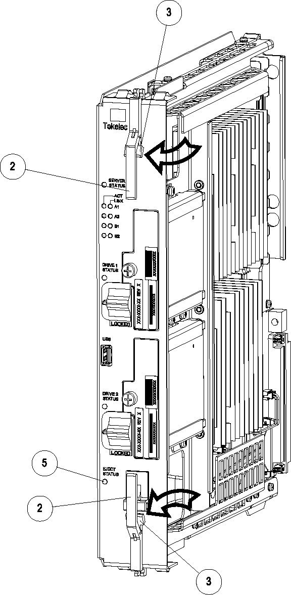
  3. Grasp the upper and lower card Inject/Eject (I/E) lever release (3) just underneath the I/E lever, and press it to meet the I/E lever. This is the mechanical interlock for the card.
    See Figure 5-2

    Figure 5-2 E5-APP-B Card UNLOCKED


    E5-APP-B Card UNLOCKED

  4. While holding the I/E interlock and lever, pull the levers (2) away from the shelf until they are parallel to the floor.
  5. Remove the E5-APP-B card from the EAGLE shelf.

5.4.2 Replacing an E5-APP-B Card

Procedure - Replace E5-APP-B card

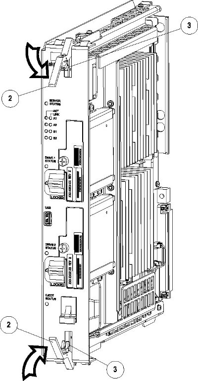
  1. While holding the I/E interlock and lever, pull the levers (2) away from the card until they are parallel to the floor.
    Figure 5-3 illustrates the angle of the interlocks and levers just before inserting E5-APP-B Card into the EAGLE shelf.

    Figure 5-3 E5-APP-B Card UNLOCKED

    E5-APP-B Card UNLOCKED
  2. Insert the E5-APP-B card into the EAGLE shelf.

    Carefully align the edges of the card with the top and bottom card guides. Then, push the card along the length of the card guides until the rear connectors on the card engage the mating connectors on the target shelf backplane.

  3. Push in the top and bottom inject/eject clamps (see Figure 5-4).

    Figure 5-4 E5-APP-B Card Inject Levers


    E5-APP-B Card Inject Levers

    This locks the card in place and ensures a strong connection with the pins on the target shelf backplane.

  4. Slide the E5-APP-B Ejector switch (4) down to the LOCKED position (see Figure 5-5).

    Note:

    When the Ejector switch goes from UNLOCKED to LOCKED, the E5-APP-B Eject Status LED blinks red as the E5-MASP card goes online.

    Figure 5-5 E5-APP-B Card Inject Hardware Switch, LOCKED


    E5-APP-B Card Inject Hardware Switch, LOCKED

  5. WAIT for the E5-APP-B Eject Status LED to go from blinking red to off.

5.5 Removing and Replacing a Drive Module Assembly

E5-APP-B cards are designed for high-availability environments, but even with the advanced reliability of the E5-APP-B card, hardware failures can occur. The E5-APP-B card is designed for easy maintenance when drive module replacement is needed. Since there are two drive modules configured with RAID in an E5-APP-B card, if one becomes corrupt the other drive continues to function. No down time is required to replace a drive module as this procedure can be used on a setup that is up and running.

Oracle now provides 480G drive modules that allow for a larger data capacity. When upgrading from 300G to 480G drive modules, both drive modules should be replaced one after the other. The 480G drive modules will support the existing data capacity and no down time is required. To take advantage of the increased storage capacity of the 480G drive modules, EPAP must be re-installed. For information about increasing the existing data capacity after upgrading to 480G drive modules, see Increasing Data Capacity with 480G Drive Modules.

Procedure - Remove and Replace a Drive Module Assembly
  1. Log in as admusr and use the smartd command to verify the drive module names.
    $ ls /var/TKLC/log/smartd
    lock log.sda log.sdb sda sdb
    In this example, the drive module names are sda and sdb.
  2. Use the mdstat command to determine whether a drive module is corrupt:
     $ sudo cat /proc/mdstat
    • On a healthy system where both drive modules (sda and sdb) are functioning properly, the mdstat output will include both drive modules:
       $ sudo cat /proc/mdstat
      Personalities : [raid1]
      md1 : active raid1 sdb2[1] sda2[0]
            262080 blocks super 1.0 [2/2] [UU]
      
      md2 : active raid1 sda1[0] sdb1[1]
            292631552 blocks super 1.1 [2/2] [UU]
            bitmap: 2/3 pages [8KB], 65536KB chunk
      
      unused devices: <none>
      
    • On a system where one of the drive modules is healthy and one is corrupt, only the healthy drive module is displayed:
       $ sudo cat /proc/mdstat
      Personalities : [raid1]
      md1 : active raid1 sdb2[1]
            262080 blocks super 1.0 [2/1] [_U]
      
      md2 : active raid1 sdb1[1]
            292631552 blocks super 1.1 [2/1] [_U]
            bitmap: 2/3 pages [8KB], 65536KB chunk
      
      unused devices: <none>
      

      In this example, the mdstat output shows only sdb, which indicates that sda is corrupt.

  3. Run the failDisk command to mark the appropriate drive module to be replaced.
    If you are replacing a healthy drive module with a higher capacity drive module, the force option is required. The force option is not required when replacing a corrupt drive module.
    • Replacing a corrupt drive module:
      $ sudo /usr/TKLC/plat/sbin/failDisk <disk to be removed>

      For example:

      $ sudo /usr/TKLC/plat/sbin/failDisk /dev/sda
    • Replacing a healthy drive module with a higher capacity drive module:
      $ sudo /usr/TKLC/plat/sbin/failDisk --force <disk to be removed>

      For example:

      $ sudo /usr/TKLC/plat/sbin/failDisk --force /dev/sda
  4. After failDisk runs successfully, remove the drive module assembly.
  5. Insert the new drive module assembly.
  6. If you are replacing a 300G drive module with a 480G drive module, repeat these steps to replace the other 300G drive module with a 480G drive module.

5.5.1 Removing a Drive Module Assembly

Procedure - Remove Drive Module Assembly

  1. Verify that the drive module is locked in position and in use.

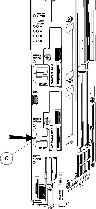
    The switch lock release (C) is in the LOCKED position and the Status LED on the E5-APP-B card is OFF.

    Move the switch lock release (C) to the "released" position by pressing in the direction indicated. Refer to Figure 5-6.

    Figure 5-6 Drive Module Released

    Drive Module Released
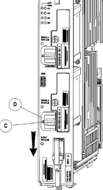
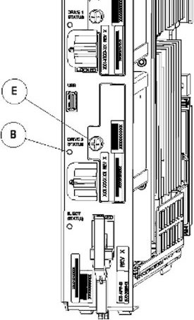
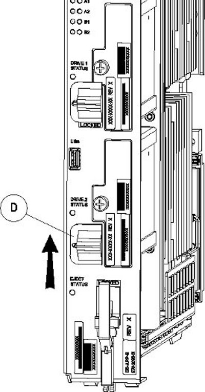
  2. Move drive module locking switch (D) from the LOCKED to the unlocked position and wait for the LED (B) to indicate a steady red state. See Figure 5-7 and Figure 5-8, respectively.
    When drive module locking switch (D) is transitioned from locked to unlocked, the LED will flash red to indicate the drive is unlocked and in process of shutting down.

    Figure 5-7 Drive Module UNLOCKED


    Drive Module UNLOCKED

    Caution:

    Removal of the drive prior to the LED indicating steady red could result in drive corruption.

    Figure 5-8 Drive Module Status


    Drive Module Status

  3. When the LED indicates a steady red, the drive module can be safely removed.
  4. Loosen the drive module screw (E) (see Figure 5-8).
  5. Grasp the screw (E) and pull the drive out slowly until it is free from the card (see Figure 5-9).

    Figure 5-9 Drive Module Removal


    Drive Module Removal

5.5.2 Replacing a Drive Module Assembly

Procedure - Replace Drive Module Assembly

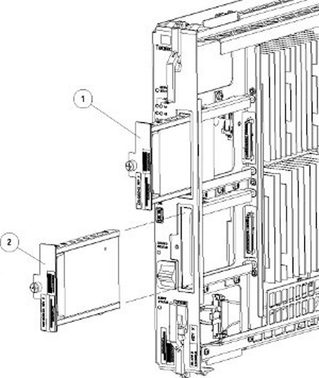
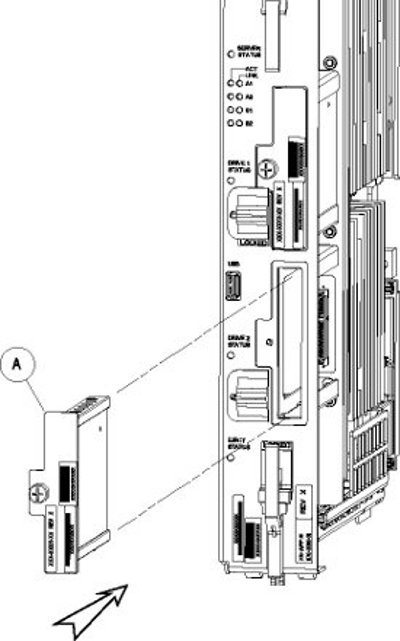
  1. Slide a new drive(s) module into the drive slot on the card (see Figure 5-10).

    Figure 5-10 Drive Module Replacement


    Drive Module Replacement

  2. Gently push the drive (A) in slowly until it is properly seated.
  3. Tighten the mounting screw until the Drive Status LED is in a steady red state ((B), from Figure 5-8).
  4. Move the drive module locking switch (D) from the unlocked to the LOCKED position.

    When drive module locking switch (D) is transitioned from unlocked to locked, the LED will flash red to indicate the drive is locked and in process of coming online (see Figure 5-11).

    Figure 5-11 Drive Module Locked


    Drive Module Locked

  5. When the LED turns off, log in as admusrroot and run the cpDiskCfg command to copy the partition table from the good drive module to the new drive module.
    $ sudo /usr/TKLC/plat/sbin/cpDiskCfg <source disk> <destination disk>
    # /usr/TKLC/plat/sbin/cpDiskCfg <source disk> <destination disk>
    For example:
    $ sudo /usr/TKLC/plat/sbin/cpDiskCfg /dev/sdb /dev/sda
    # /usr/TKLC/plat/sbin/cpDiskCfg /dev/sdb /dev/sda
  6. After successfully copying the partition table, use the mdRepair command to replicate the data from the good drive module to the new drive module.
    $ sudo /usr/TKLC/plat/sbin/mdRepair
    # /usr/TKLC/plat/sbin/mdRepair
    This step takes 45 to 90 minutes and runs in the background without impacting functionality.

    Sample output of the command:

    [admusr@recife-b ~]$ sudo /usr/TKLC/plat/sbin/mdRepair
    SCSI device 'sdb' is not currently online
    probing for 'sdb' on SCSI 1:0:0:0
    giving SCSI subsystem some time to discover newly-found disks
    Adding device /dev/sdb1 to md group md1...
    md resync in progress, sleeping 30 seconds...
    md1 is 0.0% percent done...
    
    This script MUST be allowed to run to completion.  Do not exit.
    
    
    bgRe-installing master boot loader(s)
    
    Adding device /dev/sdb2 to md group md3...
    Adding device /dev/sdb9 to md group md5...
    Adding device /dev/sdb7 to md group md4...
    Adding device /dev/sdb6 to md group md7...
    Adding device /dev/sdb8 to md group md6...
    Adding device /dev/sdb3 to md group md2...
    Adding device /dev/sdb5 to md group md8...
    md resync in progress, sleeping 30 seconds...
    md3 is 3.6% percent done...
    
    This script MUST be allowed to run to completion.  Do not exit.
    
    
    md resync in progress, sleeping 30 seconds...
    md5 is 27.8% percent done...
    
    This script MUST be allowed to run to completion.  Do not exit.
    
    md resync in progress, sleeping 30 seconds...
    md4 is 8.9% percent done...
    
    This script MUST be allowed to run to completion.  Do not exit.
    
    md resync in progress, sleeping 30 seconds...
    md4 is 62.5% percent done...
    
    This script MUST be allowed to run to completion.  Do not exit.
    
    md resync in progress, sleeping 30 seconds...
    md7 is 14.7% percent done...
    
    This script MUST be allowed to run to completion.  Do not exit.
    
    md resync in progress, sleeping 30 seconds...
    md7 is 68.3% percent done...
    
    This script MUST be allowed to run to completion.  Do not exit.
    
    md resync in progress, sleeping 30 seconds...
    md8 is 0.3% percent done...
    
    This script MUST be allowed to run to completion.  Do not exit.
    
    md resync in progress, sleeping 30 seconds...
    md8 is 1.1% percent done...
    
    This script MUST be allowed to run to completion.  Do not exit.
    
    md resync in progress, sleeping 30 seconds...
    md8 is 2.0% percent done...
    
  7. Use the cat /proc/mdstat command to confirm whether RAID repairs are successful.

    After the RAID is repaired successfully, output showing both drive modules is displayed:

    Personalities : [raid1]
    md1 : active raid1 sdb2[1] sda2[0]
          262080 blocks super 1.0 [2/2] [UU]
     
    md2 : active raid1 sda1[0] sdb1[1]
          468447232 blocks super 1.1 [2/2] [UU]
          bitmap: 1/4 pages [4KB], 65536KB chunk
     
    unused devices: <none>
    
    Personalities : [raid1]
    md2 : active raid1 sda2[0] sdb2[1]
          26198016 blocks super 1.1 [2/2] [UU]
          bitmap: 1/1 pages [4KB], 65536KB chunk
     
    md1 : active raid1 sda3[0] sdb3[1]
          262080 blocks super 1.0 [2/2] [UU]
     
    md3 : active raid1 sdb1[1] sda1[0]
          442224640 blocks super 1.1 [2/2] [UU]
          bitmap: 1/4 pages [4KB], 65536KB chunk
    
    unused devices: <none>
    

    Output of cat /proc/mdstat prior to re-mirroring:

    [admusr@recife-b ~]$ sudo cat /proc/mdstat
    Personalities : [raid1] 
    md1 : active raid1 sda1[0]
          264960 blocks [2/1] [U_]
          
    md3 : active raid1 sda2[0]
          2048192 blocks [2/1] [U_]
          
    md8 : active raid1 sda5[0]
          270389888 blocks [2/1] [U_]
          
    md7 : active raid1 sda6[0]
          4192832 blocks [2/1] [U_]
          
    md4 : active raid1 sda7[0]
          4192832 blocks [2/1] [U_]
          
    md6 : active raid1 sda8[0]
          1052160 blocks [2/1] [U_]
          
    md5 : active raid1 sda9[0]
          1052160 blocks [2/1] [U_]
          
    md2 : active raid1 sda3[0]
          1052160 blocks [2/1] [U_]
          
    unused devices: <none>
    
    
    Output of cat /proc/mdstat during re-mirroring process:
    [admusr@recife-b ~]$ sudo cat /proc/mdstat
    Personalities : [raid1] 
    md1 : active raid1 sdb1[1] sda1[0]
          264960 blocks [2/2] [UU]
          
    md3 : active raid1 sdb2[1] sda2[0]
          2048192 blocks [2/2] [UU]
          
    md8 : active raid1 sdb5[2] sda5[0]
          270389888 blocks [2/1] [U_]
          [=====>...............]  recovery = 26.9% (72955264/270389888) finish=43.8min speed=75000K/sec
          
    md7 : active raid1 sdb6[1] sda6[0]
          4192832 blocks [2/2] [UU]
          
    md4 : active raid1 sdb7[1] sda7[0]
          4192832 blocks [2/2] [UU]
          
    md6 : active raid1 sdb8[1] sda8[0]
          1052160 blocks [2/2] [UU]
          
    md5 : active raid1 sdb9[1] sda9[0]
          1052160 blocks [2/2] [UU]
          
    md2 : active raid1 sdb3[2] sda3[0]
          1052160 blocks [2/1] [U_]
          resync=DELAYED
    
    Output of cat /proc/mdstat upon successful completion of re-mirror:
    [admusr@recife-b ~]$ sudo cat /proc/mdstat
    Personalities : [raid1]
    md1 : active raid1 sdb1[1] sda1[0]
          264960 blocks [2/2] [UU]
    
    md3 : active raid1 sdb2[1] sda2[0]
          2048192 blocks [2/2] [UU]
    
    md8 : active raid1 sdb5[1] sda5[0]
          270389888 blocks [2/2] [UU]
    
    md7 : active raid1 sdb6[1] sda6[0]
          4192832 blocks [2/2] [UU]
    
    md4 : active raid1 sdb7[1] sda7[0]
          4192832 blocks [2/2] [UU]
    
    md6 : active raid1 sdb8[1] sda8[0]
          1052160 blocks [2/2] [UU]
    
    md5 : active raid1 sdb9[1] sda9[0]
          1052160 blocks [2/2] [UU]
    
    md2 : active raid1 sdb3[1] sda3[0]
          1052160 blocks [2/2] [UU]
    
    unused devices: <none>
    

5.6 Increasing Data Capacity with 480G Drive Modules

If 300G drive modules were in use when EPAP was installed, EPAP must be re-installed to take advantage of the additional storage capacity available on 480G drive modules.

Procedure - Increase Data Capacity with 480G Drive Modules

  1. Backup the data and configurations of the existing setup.
    Perform the following procedures for data backup and configurations:
    • Pre Full Upgrade Steps
      1. SETTING UP PRE-FULL UPGRADE ENVIRONMENT
      2. CAPTURING CURRENT CONFIGURATIONS
      3. CAPTURING CURRENT CONFIGURATIONS ON STANDALONE EPAP
      4. PRE-FULL UPGRADE CHECK
    • Data Backup before Full Upgrade
      1. SHUTTING DOWN THE PDBA AND EPAP
      2. DISABLE EPAP VIP AND DEACTIVATE PDBA PROXY FEATURE
      3. STOP ACTIVE PDBA AND VERIFY PDBA REPLICATION STATUS
      4. DISCONNECT REMOTE PDBA
      5. BACKUP EUIDB DATABASE
      6. BACKUP PDB
      7. BACKUP RTDB DATABASE
      8. STOP MYSQL SERVICE
      9. TRANSFER DATABASES TO MATE AND REMOTE
    For detailed configurations of these procedures, refer 3.2 Pre Full Upgrade Steps and 3.3 Data Backup before Full Upgrade in Full Upgrade Guide.
  2. If you have not already replaced both 300G drive modules with 480G drive modules, remove the 300G drive modules from the E5-APP-B card.
  3. If you have not already replaced both 300G drive modules with 480G drive modules, insert the new 480G drive modules.

    See steps 1 through 4 in Replacing a Drive Module Assembly.

  4. After the drive modules are successfully replaced, IPM the drive modules with the latest TPD and install EPAP.
    Perform the following procedures for IPM and EPAP installation:
    1. PRE INSTALL CONFIGURATION
    2. EPAP INSTALLATION
    For detailed configurations of these procedures, refer 3.4 IPM and EPAP 16.1 Installation in Full Upgrade Guide.
  5. Perform initial configuration and data migration to complete the procedure.
    Perform the following procedures for initial configuration and data migration:
    • Initial Configuration
      1. CONFIGURE NETWORK INTERFACE USING PLATCFG UTILITY
      2. CONFIGURE NETWORK INTERFACES
      3. TRANSFER DATABASES
      4. RESTORE EUIDB DATABASE
      5. CONFIGURE PROVISIONING NETWORK
      6. VERIFY CONFIGURATIONS
      7. CONFIGURE NTP SERVERS
      8. POST CONFIGURATION SYSCHECK
      9. REBOOT THE MPS
    • Data Migration
      1. RESTORE PDB
      2. RESTORE AND CONVERT RTDB
      3. VERIFY PDBA AND RTDB ARE IN SYNC
      4. RELOAD RTDB FROM MATE
      5. POINT ACTIVE PDB (2A) TO UPGRADED STANDBY PDB (1A)
      6. SET SPECIFIC RTDB HOMING
      7. POINT STANDBY PDB (1A) TO ACTIVE PDB (2A)
      8. RESTART THE PDBA AND EPAP
      9. UPDATE PDB CONFIGURATION
      10. EXCHANGE KEYS BETWEEN PROVISIONABLE AND NONPROVISIONABLE SERVERS USING SCRIPT
      11. EXCHANGE KEYS BETWEEN PROVISIONABLE AND NONPROVISIONABLE
      12. ENABLE EPAP PDBA PROXY AND EPAP VIP OPTIONAL FEATURES
      13. CONFIGURE THE AUTO BACKUP
      14. SWITCHOVER PDBA
      15. CHECK REPLICATION BETWEEN ACTIVE AND STANDBY PDBA
    For detailed configurations of these procedures, refer to 3.5 Initial Configuration on EPAP and 3.6 Data Migration in Full Upgrade Guide.