9 Servicing the DIMMs (CRU)
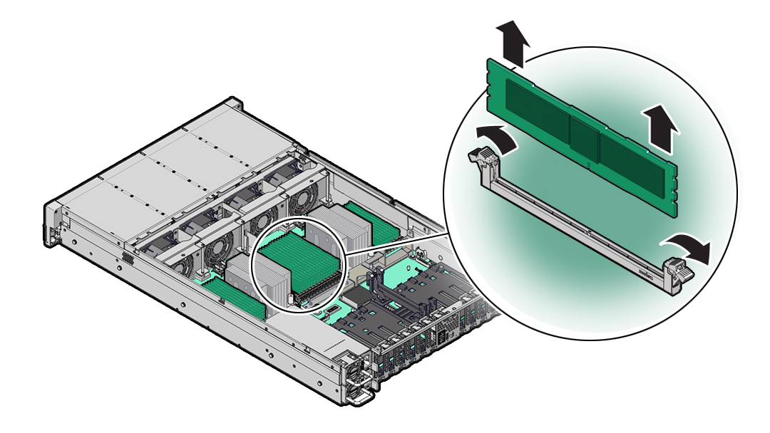
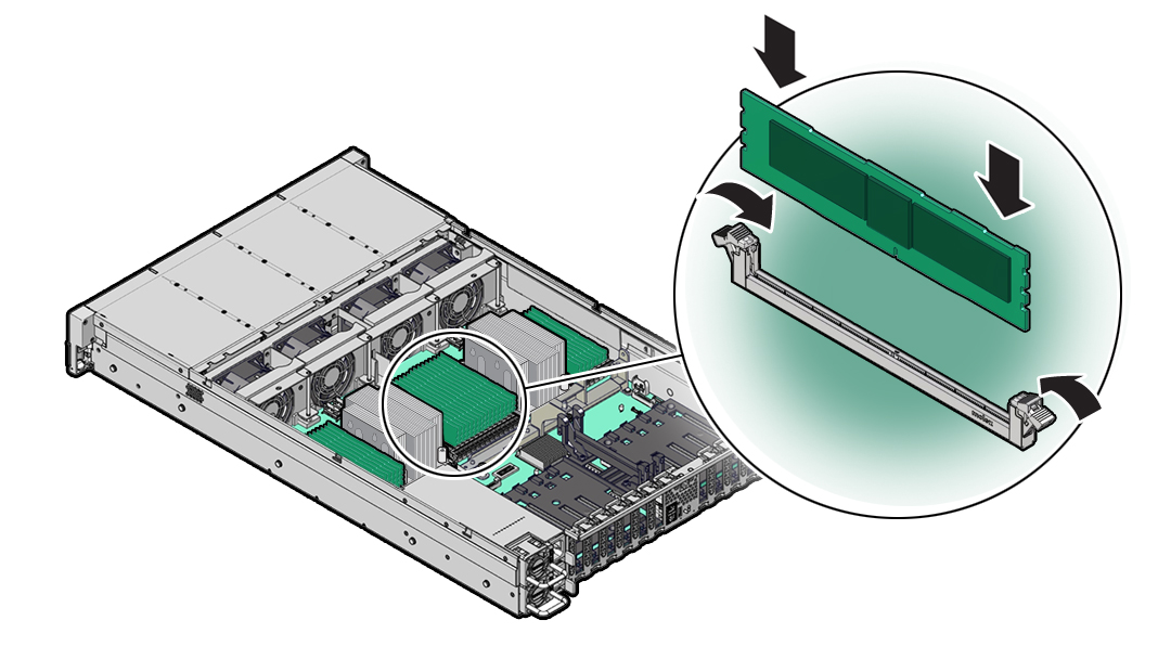
This section describes how to service memory modules (DIMMs). DIMMs are customer-replaceable units (CRUs) that require you to power off the server. For more information about CRUs, see Illustrated Parts Breakdown and Customer-Replaceable Units.
Caution:
These procedures require that you handle components that are sensitive to electrostatic discharge. This sensitivity can cause the components to fail. To avoid damage, ensure that you follow antistatic practices as described in Electrostatic Discharge Safety.Caution:
Ensure that all power is removed from the server before removing or installing DIMMs, or damage to the DIMMs might occur. You must disconnect all power cables from the system before performing these procedures.The following topics and procedures provide information to assist you when replacing a DIMM or upgrading DIMMs:
DIMM and Processor Physical Layout
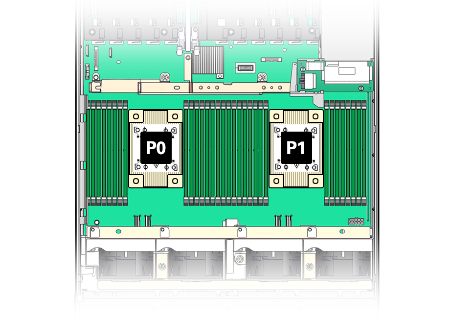
Each processor, P0 and P1, has sixteen DIMM slots organized into eight memory channels. Each memory channel contains two DIMM slots: a black DIMM slot (channel slot 0) and a white DIMM slot (channel slot 1).
The physical layout of the DIMMs and processor(s) is shown in the following figure. When viewing the server from the front, processor 0 (P0) is on the left.
| Memory Channels | DIMM Slot 0 (Black) | DIMM Slot 1 (White) |
|---|---|---|
|
0 |
D13 |
D12 |
|
1 |
D15 |
D14 |
|
2 |
D9 |
D8 |
|
3 |
D11 |
D10 |
|
4 |
D2 |
D3 |
|
5 |
D0 |
D1 |
|
6 |
D6 |
D7 |
|
7 |
D4 |
D5 |
Note:
In single-processor systems, the DIMM slots associated with processor 1 (P1) are nonfunctional and should not be populated with DIMMs.DIMM Population Scenarios
There are two scenarios in which you are required to populate DIMMs:
-
A DIMM fails and needs to be replaced.
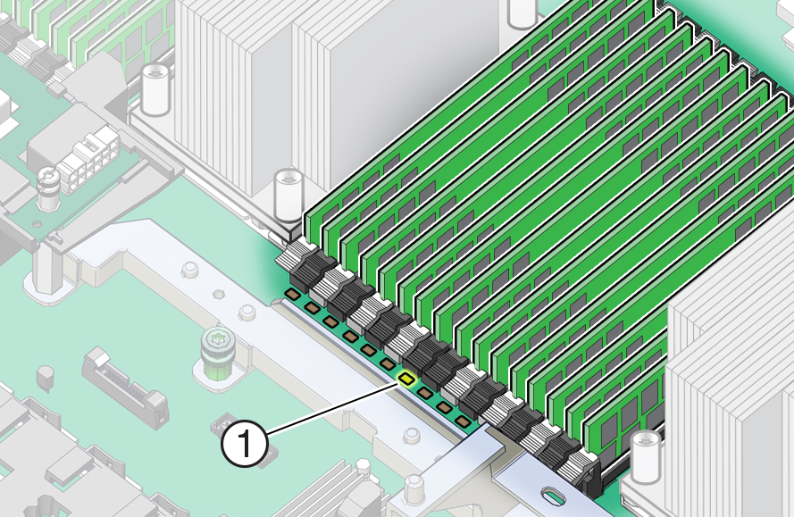
In this scenario, you can use the Fault Remind button to determine the failed DIMM, then remove the failed DIMM and replace it. To ensure that system performance is maintained, you must replace the failed DIMM with a DIMM of the same size (in gigabytes) and type (quad-rank or dual-rank). In this scenario, you should not change the DIMM configuration.
-
You have purchased new DIMMs and you want to use them to upgrade the server memory.
In this scenario, you must adhere to the DIMM population rules and follow the recommended DIMM population order for optimal system performance.
DIMM Population Rules
The population rules for adding DIMMs to the server are as follows:
-
The server supports 64-GB and 32-GB dual-rank Registered DIMMs (RDIMMs).
-
Each memory channel is composed of a black slot (channel slot 0) and a white slot (channel slot 1). Populate the black slot first, and then populate the white slot.
Note:
The black slot for each channel must be populated first because it is considered furthest away from the processor. -
The server supports either one DIMM per channel (1DPC) or two DIMMs per channel (2DPC).
-
The server operates properly with a minimum of one DIMM installed per processor.
-
The server does not support lockstep memory mode, which is also known as double device data correction, or Extended ECC.
-
Mixing of single-rank and dual-rank DIMMs in Oracle Server X9-2L is not supported.
Populating DIMMs for Optimal System Performance
Optimal performance is generally achieved by populating the DIMMs so that the memory is symmetrical, or balanced. Symmetry is achieved by adhering to the following guidelines:
-
In single-processor systems, populate DIMMs of the same size in multiples of eight.
-
In dual-processor systems, populate DIMMs of the same size in multiples of sixteen.
-
Populate the DIMM slots in the order described in the following sections, which provide an example of how to populate the DIMM slots to achieve optimal system performance.
Note:
Not all possible configurations are provided in this section.Populating DIMMs in Single-Processor Systems for Optimal System Performance
In single-processor systems, install DIMMs only into DIMM slots associated with processor 0 (P0). Starting with slot P0 D0, first fill the black slots, and then fill the white slots, as shown in the following figure.
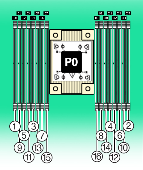
The following table describes the proper order in which to populate DIMMs in a single-processor system using the numbered callouts in the above figure, and the DIMM slot labels (D0 through D15).
| Population Order | Processor/DIMM Slot |
|---|---|
|
Populate black slots first in the following order: |
|
|
After black slots have been populated, populate white slots in the following order: |
|
Populating DIMMs in Dual-Processor Systems for Optimal System Performance
In dual-processor systems, populate DIMMs into DIMM slots starting with processor 0 (P0) D7, alternating between slots associated with processor 0 (P0) and matching slots for processor 1 (P1). Fill the black slots, and then the white slots, as shown in the following figure.
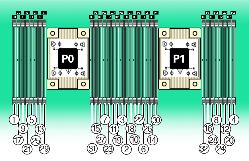
The following table describes the proper order in which to install DIMMs in a dual-processor system using the numbered callouts in the above figure, and the DIMM slot labels (D0 through D15).
| Population Order | Processor/DIMM Slot |
|---|---|
|
Populate black slots first in the following order: |
|
|
After black slots have been populated, populate white slots in the following order: |
|
The DIMM population for each processor (P0 and P1) must be identical.
Table 9-1 DIMM Memory Slot Population Requirements
| DIMMs per CPU | Channel Population Order | DIMM Memory Slots CPU-0/1 |
|---|---|---|
|
16 DIMMs per CPU |
Number Installed |
|
|
12 DIMMs per CPU |
Number Installed |
|
|
8 DIMMs per CPU |
Number Installed |
|
|
6 DIMMs per CPU |
Number Installed |
|
|
4 DIMMs per CPU |
Number Installed |
|
|
2 DIMMs per CPU |
Number Installed |
|
|
1 DIMM per CPU |
Number Installed |
|
DIMM Operating Speeds
The maximum supported memory speed is 3200 MT/s. However, not all system configurations support operation at this speed. The maximum attainable memory speed is limited by the maximum speed supported by the specific type of processor. All memory installed in the system operates at the same speed, or frequency.
DIMM Rank Classification Labels
DIMMs come in a variety of ranks: dual or quad. Each DIMM is shipped with a label identifying its rank classification. The following table identifies the label corresponding to each DIMM rank classification:
Table 9-2 DIMM Rank Classification Labels
| Rank Classification | Label |
|---|---|
|
Quad-rank LRDIMM |
4Rx4 |
|
Dual-rank RDIMM |
2Rx4 |
Inconsistencies Between DIMM Fault Indicators and the BIOS Isolation of Failed DIMMs
When a single DIMM is marked as failed by Oracle ILOM (for example, fault.memory.intel.dimm.training-failed is listed in the service processor Oracle ILOM event log), BIOS might disable the entire memory channel that contains the failed DIMM, up to two DIMMs. As a result, none of the memory installed in the disabled channel is available to the operating system. However, when the Fault Remind button is pressed, only the fault status indicator (LED) associated with the failed DIMM lights. The fault LEDs for the other DIMMs in the memory channel remain off. Therefore, you can correctly identify the failed DIMM using the lit LED.
Using the Server Fault Remind Button
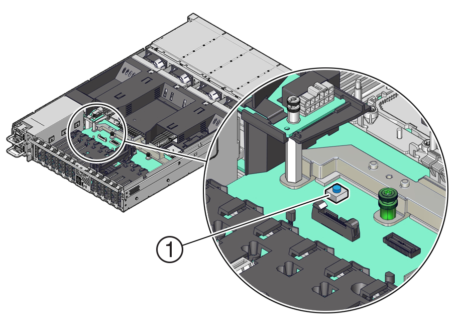
When the server Fault Remind button [1] is pressed, an LED located next to the Fault Remind button lights green to indicate that there is sufficient voltage present in the fault remind circuit to light any fault LEDs that were lit due to a component failure. If this LED does not light when you press the Fault Remind button, it is likely that the capacitor powering the fault remind circuit has lost its charge. This can happen if the Fault Remind button is pressed for several minutes with fault LEDs lit or if power has been removed from the server for more than 15 minutes.
The following figure shows the location of the Fault Remind button.
