1 About the Oracle Server X9-2L
These sections describe the controls, connectors, LEDs, system components, and replaceable components of the server:
Note:
Always update the server with the latest firmware, drivers, and other hardware-related software by downloading the latest software release package when you first receive the server, and for every new software release. For information about the software release packages and how to download the software, refer to Getting Firmware and Software in Oracle Servers X9-2 and X9-2L Installation Guide at Oracle Server X9-2L Documentation.Product Description
The Oracle Server X9-2L is an enterprise-class, two rack unit (2U) server. It supports the following components:
-
Up to two Intel processors with the following capabilities are supported:
-
Intel Xeon Platinum, 32-core, 2.6 GHz, 250 W processors
-
Intel Xeon Gold, 24-core, 2.0 GHz, 165 W processors
-
Intel Xeon Gold, 18-core, 3.0 GHz, 205 W processors
-
Intel Xeon Silver, 16-core, 2.3 GHz, 135 W processors
-
-
Up to sixteen DDR4 DIMMs per processor for a maximum of thirty-two 32-GB and 64-GB RDIMMs with speeds up to 3200 MT/sec are supported in dual-processor systems. Total supported memory is 2 TB.
-
Up to ten (four x16, eight x8) PCIe Gen4 slots are supported the dual-processor systems. PCIe slots 1 through 5 are nonfunctional in single-processor systems.
-
Storage drive configurations can include the following:
-
Up to twelve 3.5-inch hot-pluggable SAS3 hard disk drives (HDDs), or up to twelve 2.5-inch hot-pluggable PCIe Gen4 NVM-Express (NVMe) solid-state disk drives (SSDs)
-
Two hot-pluggable internal M.2 Gen3 SATA or PCIe Gen3 NVMe flash SSDs
-
-
Two hot-pluggable, redundant 1200W (or 1400W) power supplies.
-
Four hot-swappable fan modules, each containing an 80x56 mm counter-rotating dual motor fan.
-
An on-board Oracle Integrated Lights Out Manager (Oracle ILOM) service processor (SP) based on the ASPEED Pilot 4 chip.
Front and Back Panel Components
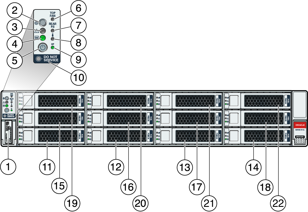
The following sections describe the controls, indicators, connectors, and drives located on the front and back panels.
Front Panel Components

| Callout | Description |
|---|---|
|
1 |
Product Serial Number (PSN) label and Radio Frequency Identification (RFID) tag |
|
2 |
Locate Button/LED: white |
|
3 |
Fault-Service Action Required LED: amber |
|
4 |
System OK LED: green |
|
5 |
On/Standby button |
|
6 |
Fault-Service Required LED: Top: Fan Module (amber) |
|
7 |
Fault-Service Required LED: Rear: Power Supply (amber) |
|
8 |
Fault-Service Required LED: Overtemp Icon: System Over Temperature Warning (amber) |
|
9 |
SP OK LED: green |
|
10 |
DO NOT SERVICE LED: white |
|
11 |
Storage drive 0 HDD/NVMe |
|
12 |
Storage drive 1 HDD/NVMe |
|
13 |
Storage drive 2 HDD/NVMe |
|
14 |
Storage drive 3 HDD/NVMe |
|
15 |
Storage drive 4 HDD/NVMe |
|
16 |
Storage drive 5 HDD/NVMe |
|
17 |
Storage drive 6 HDD/NVMe |
|
18 |
Storage drive 7 HDD/NVMe |
|
19 |
Storage drive 8 HDD/NVMe |
|
20 |
Storage drive 9 HDD/NVMe |
|
21 |
Storage drive 10 HDD/NVMe |
|
22 |
Storage drive 11 HDD/NVMe |
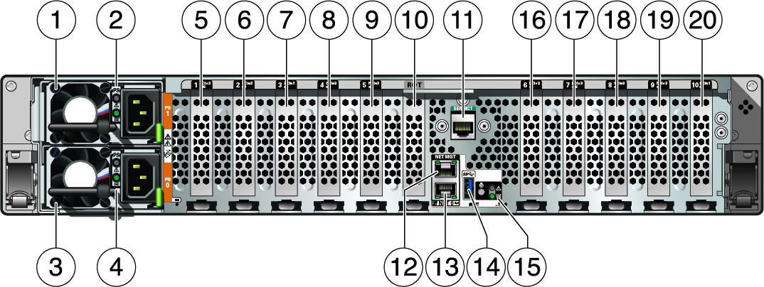
Back Panel Components and Cable Connections

Note:
For more information on back panel components and connections, see Back Panel Connector Locations. See also Back Panel Pinhole Switch.About System Components
These sections describe the components of the server:
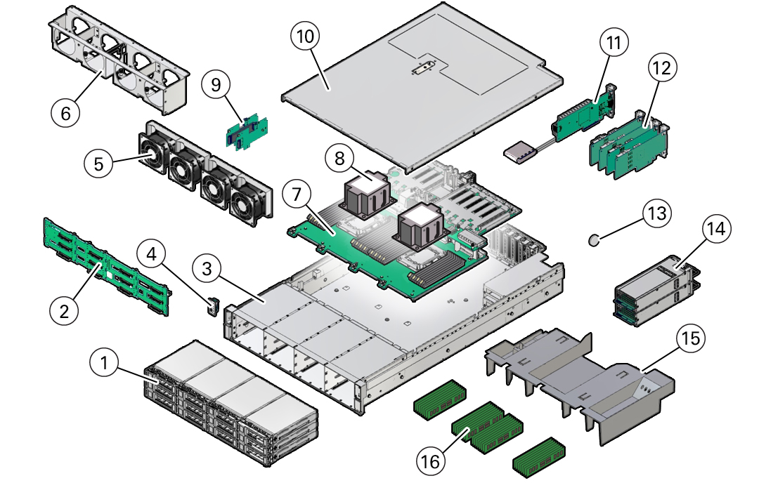
Illustrated Parts Breakdown
The following figure identifies the major components of the server.

| Callout | Description |
|---|---|
|
1 |
Twelve storage drives |
|
2 |
Disk backplane |
|
3 |
System chassis |
|
4 |
Front LED indicator module and temperature sensor |
|
5 |
Fan modules |
|
6 |
Fan tray |
|
7 |
Motherboard assembly |
|
8 |
Processors and heatsinks (Single-processor systems contain only a single processor in socket P0; socket P1 contains a cover to protect processor socket pins.) |
|
9 |
Internal M.2 SATA |
|
10 |
Top cover |
|
11 |
(Optional) Oracle Storage 12 Gb SAS PCIe RAID HBA, Internal card and super capacitor for SAS storage drive configurations, or an Oracle Retimer card (not shown) for NVMe storage drive configurations that include NVMe storage drives in slots 8 through 11. |
|
12 |
PCIe cards (PCIe slots 1 through 5 are nonfunctional in single-processor systems.) |
|
13 |
System battery |
|
14 |
Power supplies |
|
15 |
Air baffle |
|
16 |
DIMMs (Sixteen DIMMs are supported in single-processor systems and the DIMMs must be installed in P0 DIMM sockets.) |
Customer-Replaceable Units
The following table lists the customer-replaceable units (CRUs) in the server and directs you to the replacement instructions.
| CRU (Service Level) | Description | Replacement Instructions |
|---|---|---|
|
Battery (Cold service) |
Lithium coin-cell battery that powers the CMOS BIOS and real-time clock. |
|
|
Air baffle (Cold service) |
Aids in the cooling the system components. |
|
|
DIMMs (Cold service) |
Add or replace memory modules in the system. |
|
|
Storage drives (Hot service) |
Storage drive configurations can be comprised of both hard disk drives (HDDs), solid state disk drives (SSDs), or NVMe drives. Configurations include:
|
|
|
Internal M.2 flash SSDs (Hot service) |
Supports up to two hot-pluggable internal M.2 SATA or NVMe flash SSDs. |
|
|
Fan modules (Hot service) |
Four fan modules for cooling the server components. |
|
|
PCIe cards (Cold service) |
Optional add-on cards that can expand the functionality of the server. |
|
|
Power supply units (Hot service) |
Two fully redundant AC-powered power supplies. |
Field-Replaceable Units
The following table lists the field-replaceable units (FRUs) in the server and directs you to the replacement instructions.
| FRU (Service Level) | Description | Replacement Instructions |
|---|---|---|
|
Processor and heatsink (Cold service) |
Processor that carries out the instructions of the system. |
|
|
Disk backplane (Cold service) |
Provides power and communications connectors for storage drives. |
|
|
SAS cables (Cold service) |
Provides signals between the front disk backplane and the Oracle Storage 12 Gb SAS PCIe RAID HBA, Internal card. |
|
|
NVMe cables (Cold service) |
Provides signals between the Oracle Retimer card located in PCIe slot 10 and the disk backplane. Note: NVMe cables between the Oracle Retimer card and the storage backplane are required if storage drive slots 8 through 11 contain NVMe SSDs. |
|
|
Oracle Storage 12 Gb SAS PCIe RAID HBA, Internal card and super capacitor (Cold service) |
Located in PCIe slot 10, the Oracle Storage 12 Gb SAS PCIe RAID HBA, Internal card manages SAS storage drives. |
Servicing the Internal HBA Card and HBA Super Capacitor (FRU) |
|
Front LED indicator module (Cold service) |
Contains the push-button circuitry and LEDs that are displayed on the front panel. |
|
|
Temperature sensor (Cold service) |
Provides temperature information for the system. |
|
|
Motherboard assembly (Cold service) |
Provides connectors for the DIMMs, processors, PCIe risers, and other components. |