A Card Removal/Replacement Procedures

A.1 Introduction

This appendix explains how to remove a card from the EAGLE. The procedures include the administrative commands required to take a card out of service and place it back into service.

In the event a numbered event message is encountered, refer to the appropriate procedure in Unsolicited Alarm and Information Messages Reference.

Additional information about each command can be found in Commands User's Guide.

Caution:

Always wear a wrist strap or other electrostatic protection when handling EAGLE cards.

Caution:

Always place removed cards into an electrostatic protection bag before sending to Oracle, or storing in inventory (unless the card is being stored in the optional spare card storage shelf).

Note:

For the complete list of cards supported by EAGLE Release 47.0, see Hardware Reference Guide.

A.2 EAGLE Replacement Parts List

For a listing of field replaceable parts and cables used in the EAGLE and their part numbers, refer to the tables in Part Numbers.

All parts must be replaced through the Return Material Authorization (RMA) process. Contact the My Oracle Support (MOS), before replacing any parts.

A.3 E5-MASP Card Replacement

This procedure is to replace an E5-MASP card. Before the E5-MASP is replaced, it must be verified that it is the standby MASP.

The E5-MASP (made up of the E5-MCAP and E5-TDM cards) contains the removable USB drive, the fixed disk drive, the terminal processor for the 16 serial I/O ports, and an interface to the maintenance disk and alarm (E5-MDAL) card.

  1. Before beginning this procedure, make sure there is a copy of the current release GPLs on a removable USB drive on-hand.
  2. If the active E5-MASP card fails, the EAGLE automatically switches activity to the standby MASP.
  3. Enter the following command to display the card status:
    rept-stat-card

    The following is an example of a possible output.

    
        e5oam 08-12-01 15:38:32 EST  EAGLE 40.1.0
        CARD   VERSION      TYPE      GPL        PST            SST        AST
        1108   -----------  MCPM      MCP        OOS-MT-DSBLD   Manual     -----
        1109   030-009-000  HIPR2     HIPR2      IS-NR          Active     -----
        1110   030-009-000  HIPR2     HIPR2      IS-NR          Active     -----
        1111   030-010-000  IPSM      IPS        IS-NR          Active     -----
        1113 030-010-008 E5MCAP OAMHC IS-NR Standby -----
        1114   -----------  E5TDM                IS-NR          Active     -----
        1115   030-010-008  E5MCAP    OAMHC      IS-NR          Active     -----
        1116   -----------  E5TDM                IS-NR          Active     -----
        1117   -----------  E5MDAL               OOS-MT         Isolated   -----
    
        Command Completed.


    In this sample output, 1113/1114 are standby and 1115/1116 are active. Perform 5 only if the card to be replaced is not Standby.

  4. From the output of the rept-stat-card command, executed in 3, determine the MASP activity.

    Record which E5-MCAP is Active and Standby. Record the card locations of both sets of E5-MCAPs and E5-TDMs.

    Table A-1 Card Locations

    Card Location

    Active E5MCAP


    Active E5TDM


    Standby E5MCAP


    Standby E5TDM

     
  5. Verify the E5-MASP card to be replaced (failing or non-failing) is Standby before continuing.
    1. If the E5-MASP card is failing it should already be Standby. Go to 7
    2. If the card is not Standby and needs replacement, enter the following command to verify the database:
      rept-stat-db:display=all

      Verify all the cards in the system have the same database count. If the counts do not match, contact My Oracle Support (MOS).

    3. Enter the following command to force the active E5-MASP card to become Standby:
      init-card:loc=x

      where x is the card location (1113 or 1115) from 3.

  6. If 5 was performed, execute the rept-stat-card command and verify if the card to be replaced is part of the Standby MASP.
  7. If a failing E5-TDM card is to be replaced, perform a database backup before replacing the failed card.
    Insert the removable USB drive with the current release GPLs into the Active E5-MASP removable USB port. Using Daily Procedures, create a backup of the database on the Active removable USB drive. Then go to 9.

    warning:

    Do not proceed to 9 if the backup fails. Contact My Oracle Support (MOS).
  8. If a non-failing E5-TDM card is to be replaced, insert the removable USB drive containing the copy of the current release GPLs into the Active E5-MASP.
  9. Enter the following command to verify that the security log on the standby MASP contains no entries that must be copied to the FTA area of the fixed disk:
    rept-stat-seculog

    The following is an example of a possible output.

    
    RLGHNCXA03W 96-10-04 15:59:06 EDT EAGLE 34.0.0
                 -- SINCE LAST UPLOAD --  OLDEST   NEWEST   LAST
    LOC  ROLE    ENTRIES %FULL OFLO FAIL  RECORD   RECORD   UPLOAD
    1114 Active  8312    84    No   No    95-08-12 96-01-04 96-12-16
                                          11:23:56 15:59:06 14:02:22 
    1116 Standby 693     7     No   No    95-09-12 95-09-30 95-09-30
                                          11:24:12 14:00:06 14:02:13
    
    • If the number shown in the ENTRIES field for the standby MASP (shown with the entry Standby in the ROLE field) is 0, go to 12.
    • If the number shown in the ENTRIES field for the standby MASP is greater than 0, these entries must be copied to the FTA area of the fixed disk.
    To copy these entries, go to the next step.
  10. Copy the security log entries on the standby MASP to the FTA area on the fixed disk using the following command:
    copy-seculog:slog=stb:dloc=act

    The following is a possible output of the message that should appear (the copy-seculog:slog=stb command was used).

    
    RLGHNCXA03W 96-10-04 15:59:06 EDT EAGLE 34.0.0
    Security log on E5TDM 1116 copied to file 961004s.log on E5TDM 1114
    
  11. Remove the card from service by entering the following command:
    rmv-card:loc=xxxx

    where xxxx is the card location.

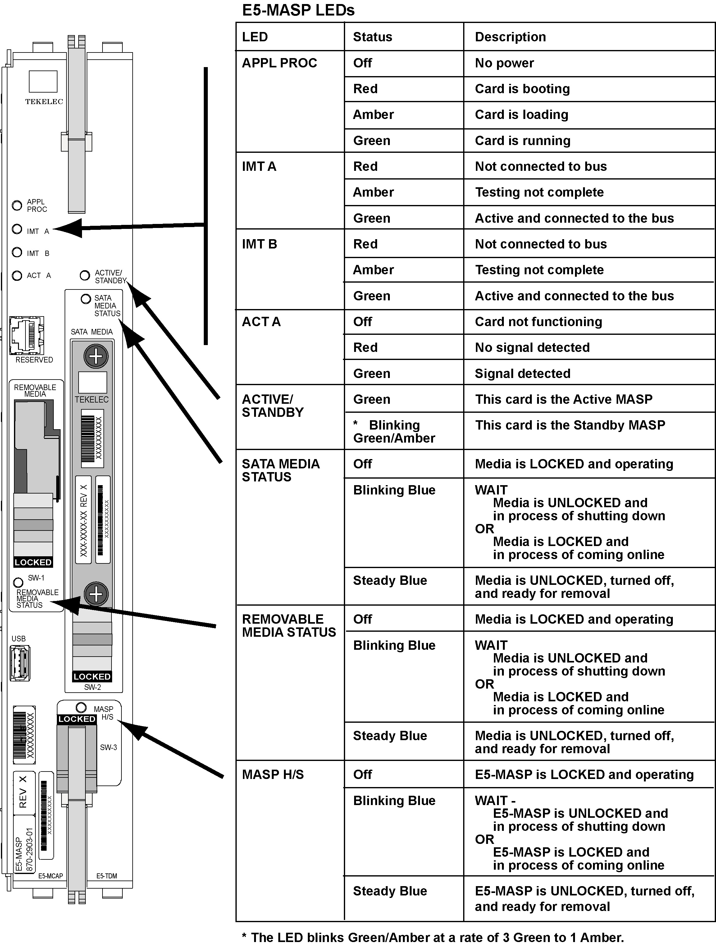
  12. Replace the Standby E5-MASP. Refer to Figure A-3 for description ofthe E5-MASP LEDs.
    1. On the standby E5-MASP card determined in 6 , slide the MASP H/S switch (SW3) up to the UNLOCKED position (see Figure A-1).

      Caution:

      When the Ejector switch goes from locked to unlocked and the E5-APP-B card is in service, the card will halt.

      Figure A-1 E5-MASP Card Inject/Eject Hardware Switch, UNLOCKED

      img/870-2903-xx_e5-masp_board_latch_unlocked.jpg
    2. WAIT for the MASP H/S LED to go from blinking blue to a steady blue.
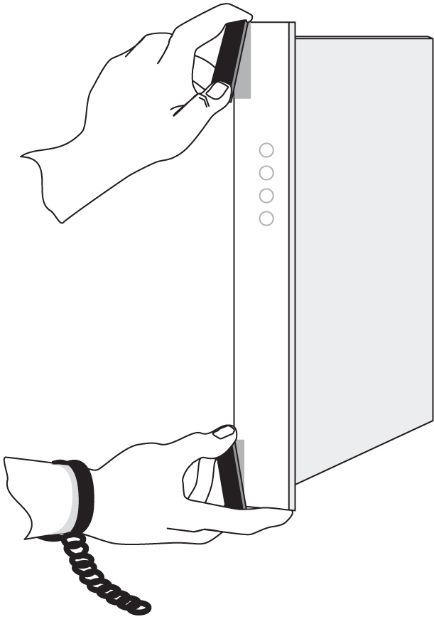
    3. Grasp the upper and lower card Inject/Eject (I/E) lever release interlock, located just underneath the I/E lever, and press it to meet the I/E lever. This is the mechanical interlock for the card.
    4. While holding the I/E interlock and lever, pull the levers away from the shelf until they are parallel to the floor.
    5. Remove the standby E5-MASP card. Gently pull the card towards you until the card clears the shelf.

      Note:

      UAMs are generated during this step. An audible alarm is generated.
    6. Place the card you have removed in an electrostatic discharge (ESD) protective container, or place the card in the spare card storage shelf.
    7. Be sure that the replacement card has the same Oracle part number and revision number as the card you have just removed.
    8. Open the ejector levers on the replacement card. Insert the spare E5-MASP card.
      Carefully align the card’s edges with the top and bottom card guides. Then push the card along the length of the card guides until the rear connectors on the card engage the mating connectors on the target shelf backplane.

      Note:

      UAMs are generated during this step. An audible alarm is generated. Wait for the E5-MASP card to come up to standby mode.
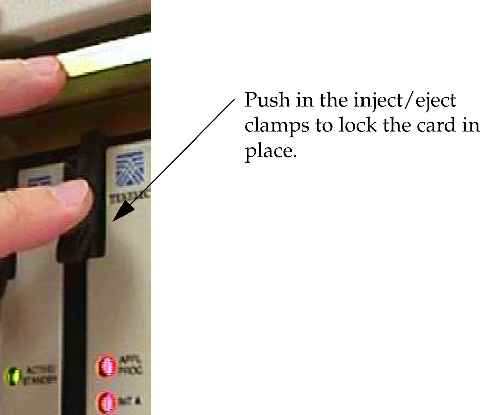
    9. Push in the top and bottom inject/eject clamps.

      This locks the card in place and ensures a strong connection with the pins on the target shelf backplane.

    10. Slide the MASP H/S switch (SW3) down to the LOCKED position (see Figure A-2).

      Note:

      When the Ejector switch goes from UNLOCKED to LOCKED, the E5-APP-B Eject Status LED blinks red as the E5-MASP card goes online.

      Figure A-2 E5-MASP Card Inject/Eject Hardware Switch, LOCKED

      img/870-2903-xx_e5-masp_board_latch_locked.jpg
    11. WAIT for the MASP H/S LED to go from blinking blue to off.
  13. Insert the removable USB drive containing the appropriate GPLs from 1 into the newly installed E5-MASP. (Refer to Removable USB Drive.)
  14. Enter the following command to change the state of the appropriate card to the out of service - maintenance disabled state:
    inh-card:loc=xxxx:force=yes

    where xxxx is the card location stenciled on the shelf of the EAGLE. Following is an example of a possible output:

    
    RLGHNCXA03W  00-06-05  11:11:28 EDT  EAGLE 34.0.0
    Card has been inhibited.
    
  15. Enter the following command to load and activate the approved GPL onto the inhibited card:
    flash-card:code=appr:loc=xxxx:force=yes

    where xxxx is the card location used in the previous step. The optional force=yes is used to force the command to work on an IS-NR card.

  16. Enter the following command to put the card that was inhibited in 14 back into service:
    alw-card:loc=xxxx

    where xxxx is the card location used in 14. Following is an example of a possible output:

    
    RLGHNCXA03W  00-06-05  11:11:28 EDT  EAGLE 34.0.0
    Card has been allowed.
    

    Note:

    Allow the card to run for 5 minutes before continuing.
  17. Enter the following command to verify the database is consistent (same level as the other cards in the system).
    rept-stat-db:display=version

    The following is an example of a possible output.

    
    rlghncxa03w 13-04-19 12:38:29 EST  EAGLE5 45.0.0-64.62.0
    DATABASE STATUS: >> OK <<
                E5TDM 1114 ( STDBY)                 E5TDM 1116 ( ACTV )
                C   LEVEL    TIME LAST BACKUP     C   LEVEL    TIME LAST BACKUP
                - -------- ---------------------- - -------- ----------------------
        FD BKUP Y      175 13-04-16 16:09:11 MST  Y      175 13-04-16 16:09:11 MST
        FD CRNT Y      218                        Y      218
                MCAP 1113                         MCAP 1115
                - --------                        - --------
        RD BKUP Y        1     -        -         Y        1     -        -
        USB BKP -    -         -        -         -    -         -        -
    
        CARD/APPL  LOC   C  T  LEVEL       TIME LAST UPDATE   VERSION STATUS
        ---------  ----  -  -  ----------  -----------------  -------------------
        OAMHC-RMV    1113  Y  -  1               -        -     135-000-000  NORMAL
        E5TDM-CRNT   1114  Y  N  218         13-04-18 19:07:14  135-000-000  NORMAL
        E5TDM-BKUP   1114  Y  -  175         13-04-16 15:51:32  135-000-000  NORMAL
        OAMHC-RMV    1115  Y  -  1               -        -     135-000-000  NORMAL
        OAMHC-USB    1115  -  -      -           -        -          -
        E5TDM-CRNT   1116  Y  N  218         13-04-18 19:07:14  135-000-000  NORMAL
        E5TDM-BKUP   1116  Y  -  175         13-04-16 15:51:32  135-000-000  NORMAL
        ;
     
  18. Compare the VERSION STATUS of the E5-TDM cards in the output of the previous step.
    • If they are identical, continue to the next step.
    • If they are not the same, go to 23
  19. Enter the following command to repair the standby’s E5-MASP database:
    chg-db:action=repair

    Note:

    The system requires approximately two minutes after 16 to acquire duplex mode. As a result, the system will reject the chg-db:action= repair until duplex operation fully returns.

    The following is an example of a possible output.

    
    RLGHNCXA03W 03-08-27 03:46:49 EST  EAGLE 34.0.0
    chg-db:action=repair
    Command entered at terminal #10.
    ;
    RLGHNCXA03W 03-08-27 03:46:50 EST  EAGLE 34.0.0
    REPAIR: MASP A - Repair starts on standby MASP.
    ;
    

    Note:

    Observe that the command execution time may require approximately 20 to 45 minutes.
    
    RLGHNCXA03W 03-08-27 04:15:22 EST  EAGLE 34.0.0
    REPAIR: MASP A - Repair from fixed disk complete.
    ;
    

    Wait for the ‘repair complete’ message to display and for the to MASP return to in-service status. When the ‘repair complete’ message has displayed, proceed to 20

    Note:

    Perform this step only if you are coming from 18.
  20. Enter the following command to show the version numbers of the GPLs stored on each fixed disk (E5-TDM).
    rtrv-gpl

    The following is an example of a possible output.

        tekelecstp 18-01-18 21:23:11 EST  EAGLE 46.5.1.5.0-73.10.0
        rtrv-gpl
        Command entered at terminal #18.
    ;
    
    Command Accepted - Processing
        tekelecstp 18-01-18 21:23:11 EST  EAGLE 46.5.1.5.0-73.10.0
        GPL Auditing  ON
    
        GPL       CARD  RELEASE      APPROVED         TRIAL        REMOVE TRIAL
        OAMHC     1114  143-010-000  143-010-000 ALM  -----------  -----------
        OAMHC     1116  143-010-000  143-010-000 ALM  -----------  -----------
        OAMHC     1115  -----------  -----------      -----------  -----------
        OAMHC69   1114  143-010-000  143-010-000 ALM  -----------  -----------
        OAMHC69   1116  143-010-000  143-010-000 ALM  -----------  -----------
        OAMHC69   1115  -----------  -----------      -----------  -----------
        IPSG32    1114  143-010-000  143-010-000      143-010-000  -----------
        IPSG32    1116  143-010-000  143-010-000      143-010-000  -----------
        IPSG32    1115  -----------  -----------      -----------  -----------
        BLMCAP    1114  143-010-000  143-010-000      143-010-000  -----------
        BLMCAP    1116  143-010-000  143-010-000      143-010-000  -----------
        BLMCAP    1115  -----------  -----------      -----------  -----------
        HIPR2     1114  143-010-000  143-010-000      143-010-000  -----------
        HIPR2     1116  143-010-000  143-010-000      143-010-000  -----------
        HIPR2     1115  -----------  -----------      -----------  -----------
        SFAPP     1114  143-010-000  143-010-000 ALM  143-010-000  -----------
        SFAPP     1116  143-010-000  143-010-000 ALM  143-010-000  -----------
        SFAPP     1115  -----------  -----------      -----------  -----------
        SS7HC     1114  143-010-000  143-010-000      143-010-000  -----------
        SS7HC     1116  143-010-000  143-010-000      143-010-000  -----------
        SS7HC     1115  -----------  -----------      -----------  -----------
        SCCPHC    1114  143-010-000  143-010-000      143-010-000  -----------
        SCCPHC    1116  143-010-000  143-010-000      143-010-000  -----------
        SCCPHC    1115  -----------  -----------      -----------  -----------
        ERTHC     1114  143-010-000  143-010-000      143-010-000  -----------
        ERTHC     1116  143-010-000  143-010-000      143-010-000  -----------
        ERTHC     1115  -----------  -----------      -----------  -----------
        IPSHC     1114  143-010-000  143-010-000      143-010-000  -----------
        IPSHC     1116  143-010-000  143-010-000      143-010-000  -----------
        IPSHC     1115  -----------  -----------      -----------  -----------
        ATMHC     1114  143-010-000  143-010-000      143-010-000  -----------
        ATMHC     1116  143-010-000  143-010-000      143-010-000  -----------
        ATMHC     1115  -----------  -----------      -----------  -----------
        IPSG      1114  143-010-000  143-010-000      143-010-000  -----------
        IPSG      1116  143-010-000  143-010-000      143-010-000  -----------
        IPSG      1115  -----------  -----------      -----------  -----------
        PKTGHC    1114  143-010-000  143-010-000      -----------  -----------
        PKTGHC    1116  143-010-000  143-010-000      -----------  -----------
        PKTGHC    1115  -----------  -----------      -----------  -----------
        BLIXP     1114  143-010-000  143-010-000      143-010-000  -----------
        BLIXP     1116  143-010-000  143-010-000      143-010-000  -----------
        BLIXP     1115  -----------  -----------      -----------  -----------
        MCPHC     1114  143-010-000  143-010-000      143-010-000  -----------
        MCPHC     1116  143-010-000  143-010-000      143-010-000  -----------
        MCPHC     1115  -----------  -----------      -----------  -----------
        SIPHC     1114  143-010-000  143-010-000      143-010-000  -----------
        SIPHC     1116  143-010-000  143-010-000      143-010-000  -----------
        SIPHC     1115  -----------  -----------      -----------  -----------
        DEIRHC    1114  143-010-000  143-010-000      143-010-000  -----------
        DEIRHC    1116  143-010-000  143-010-000      143-010-000  -----------
        DEIRHC    1115  -----------  -----------      -----------  -----------
        ENUMHC    1114  143-010-000  143-010-000      143-010-000  -----------
        ENUMHC    1116  143-010-000  143-010-000      143-010-000  -----------
        ENUMHC    1115  -----------  -----------      -----------  -----------
        PKTG64    1114  143-010-000  143-010-000      -----------  -----------
        PKTG64    1116  143-010-000  143-010-000      -----------  -----------
        PKTG64    1115  -----------  -----------      -----------  -----------
        BLDC64    1114  143-010-000  -----------      143-010-000  -----------
        BLDC64    1116  143-010-000  000-000-000 ALM  143-010-000  -----------
        BLDC64    1115  -----------  -----------      -----------  -----------
        SCCP64    1114  143-010-000  143-010-000      143-010-000  -----------
        SCCP64    1116  143-010-000  143-010-000      143-010-000  -----------
        SCCP64    1115  -----------  -----------      -----------  -----------
        BLSLC32   1114  143-010-000  143-010-000      143-010-000  -----------
        BLSLC32   1116  143-010-000  143-010-000      143-010-000  -----------
        BLSLC32   1115  -----------  -----------      -----------  -----------
        BLSLC64   1114  143-010-000  143-010-000      143-010-000  -----------
        BLSLC64   1116  143-010-000  143-010-000      143-010-000  -----------
        BLSLC64   1115  -----------  -----------      -----------  -----------
        SIP64     1114  143-010-000  143-010-000      143-010-000  -----------
        SIP64     1116  143-010-000  143-010-000      143-010-000  -----------
        SIP64     1115  -----------  -----------      -----------  -----------
        DEIR64    1114  143-010-000  143-010-000      143-010-000  -----------
        DEIR64    1116  143-010-000  143-010-000      143-010-000  -----------
        DEIR64    1115  -----------  -----------      -----------  -----------
        ENUM64    1114  143-010-000  143-010-000      143-010-000  -----------
        ENUM64    1116  143-010-000  143-010-000      143-010-000  -----------
        ENUM64    1115  -----------  -----------      -----------  -----------
        BLDC32    1114  143-010-000  -----------      143-010-000  -----------
        BLDC32    1116  143-010-000  -----------      143-010-000  -----------
        BLDC32    1115  -----------  -----------      -----------  -----------
        MCPHC69   1114  143-010-000  143-010-000      143-010-000  -----------
        MCPHC69   1116  143-010-000  143-010-000      143-010-000  -----------
        MCPHC69   1115  -----------  -----------      -----------  -----------
        IPSHC69   1114  143-010-000  143-010-000      143-010-000  -----------
        IPSHC69   1116  143-010-000  143-010-000      143-010-000  -----------
        IPSHC69   1115  -----------  -----------      -----------  -----------
        BLSL932   1114  143-010-000  143-010-000      143-010-000  -----------
        BLSL932   1116  143-010-000  143-010-000      143-010-000  -----------
        BLSL932   1115  -----------  -----------      -----------  -----------
    
    ;
    Command Executed
    
    
  21. Examine the output of the previous step.
    1. If any version is different continue with 22.
    2. If there are no differences, go to 27.
  22. Enter the following command to load the GPLs from the removable USB drive inserted in 13:
    copy-gpl:sloc=xxxx:dloc=yyyy

    where xxxx is the card location used in 14 and yyyy is the mated E5-TDM location.

    The following is an example of a possible output.

        rlghncxa03w 09-01-07 00:57:31 EST  EAGLE 40.1.0
        COPY GPL:  MASP B - COPY STARTS ON REMOVABLE DRIVE
    ;
    
        rlghncxa03w 09-01-07 01:01:27 EST  EAGLE 40.1.0
        COPY GPL:  MASP B - COPY TO STANDBY MASP COMPLETE
    

    When the command has completed, go to 27

  23. Enter the following command to verify whether measurement collection is on or off:
    rtrv-meas-sched

    The following is an example of a possible output. The COLLECT field shows whether measurement collection is on or off. In this example, measurement collection is on.

    
    RLGHNCXA03W 95-04-03 12:22:55 EST EAGLE 34.0.0
    COLLECT        =  on
    ---------------------
    SYSTOT-STP     =  off
    SYSTOT-TT      =  off
    COMP-LNKSET    =  off
    COMP-LINK      =  on
    MTCD-STP       =  on
    MTCD-LINK      =  on
    • If measurement collection is on, continue with 24.
    • If measurement collection is off, proceed to 25.
  24. Enter the following command to inhibit all measurements:
    chg-meas:collect=off

    Caution:

    Measurements must be inhibited or the copy-disk command cannot be executed. The chg-meas:collect=on command should not be executed while the copy-disk command is in progress. When measurements are inhibited, measurement collection is stopped. For the entire period of time when measurements are inhibited, those measurements will be lost. If possible do not inhibit measurements at midnight since doing so can result in the loss of measurements for an entire day.

    The following is an example of a possible output of the message that should appear.

    
    RLGHNCXA03W 94-02-07 16:12:50 EST  EAGLE 34.0.0
    CHG-MEAS: MASP A - COMPLTD
    
  25. Enter the following copy-disk command along with the card location of the standby E5-TDM (shown by the indicator STDBY in the command output in 17) that the data is being copied to.
    copy-disk:dloc=xxxx:format=yes

    Where xxxx is the card location of the standby E5-TDM.

    This command can take from 33 minutes to 1 hour 46 minutes to execute. It can take even longer depending on other system activity in progress when this command is entered.

    The following is an example of a possible output of the message that should appear when the command has executed and completed. For this example, the copy-disk:dloc=1116 command was entered.

    
    Copy-disk (fixed): from active (1114) to standby (1116) started.
    Extended processing required, please wait.
    Copy-disk (fixed): from active (1114) to standby (1116) completed.
    Measurements collection may be turned on now if desired.
    
    The standby MASP is rebooted to load the data when the command completes successfully.

    Note:

    While this command is executing, commands that affect the database configuration cannot be executed. Any attempt to execute such a command will be rejected.
  26. If measurement collection was turned off in 24, enter the following command to turn on the measurements:
    chg-meas:collect=on

    The following is an example of a possible output of the message that should appear.

    
    RLGHNCXA03W 94-02-07 16:12:50 EST  EAGLE 34.0.0
    CHG-MEAS: MASP A - COMPLTD
    
  27. Enter the following command to verify that the database counts of both MASPs.
    rept-stat-db:display=all

    The following is an example of the possible output for a good database.

    
    rept-stat-db
    Command Accepted - Processing
        rlghncxa03w 13-04-19 12:51:29 EST  EAGLE5 45.0.0-64.62.0
        rept-stat-db
        Command entered at terminal #4.
    ;
        rlghncxa03w 13-04-19 12:51:29 EST  EAGLE5 45.0.0-64.62.0
        DATABASE STATUS: >> OK <<
                E5TDM 1114 ( STDBY)                 E5TDM 1116 ( ACTV )
                C   LEVEL    TIME LAST BACKUP     C   LEVEL    TIME LAST BACKUP
                - -------- ---------------------- - -------- ----------------------
        FD BKUP Y      175 13-04-16 16:09:11 MST  Y      175 13-04-16 16:09:11 MST
        FD CRNT Y      218                        Y      218
                MCAP 1113                         MCAP 1115
                - --------                        - --------
        RD BKUP Y        1     -        -         Y        1     -        -
        USB BKP -    -         -        -         -    -         -        -
        ;
    

Figure A-3 E5-MASP LEDs

img/870-2903-xx_e5_masp_led_table.jpg

A.4 E5-MDAL Card Replacement

Description

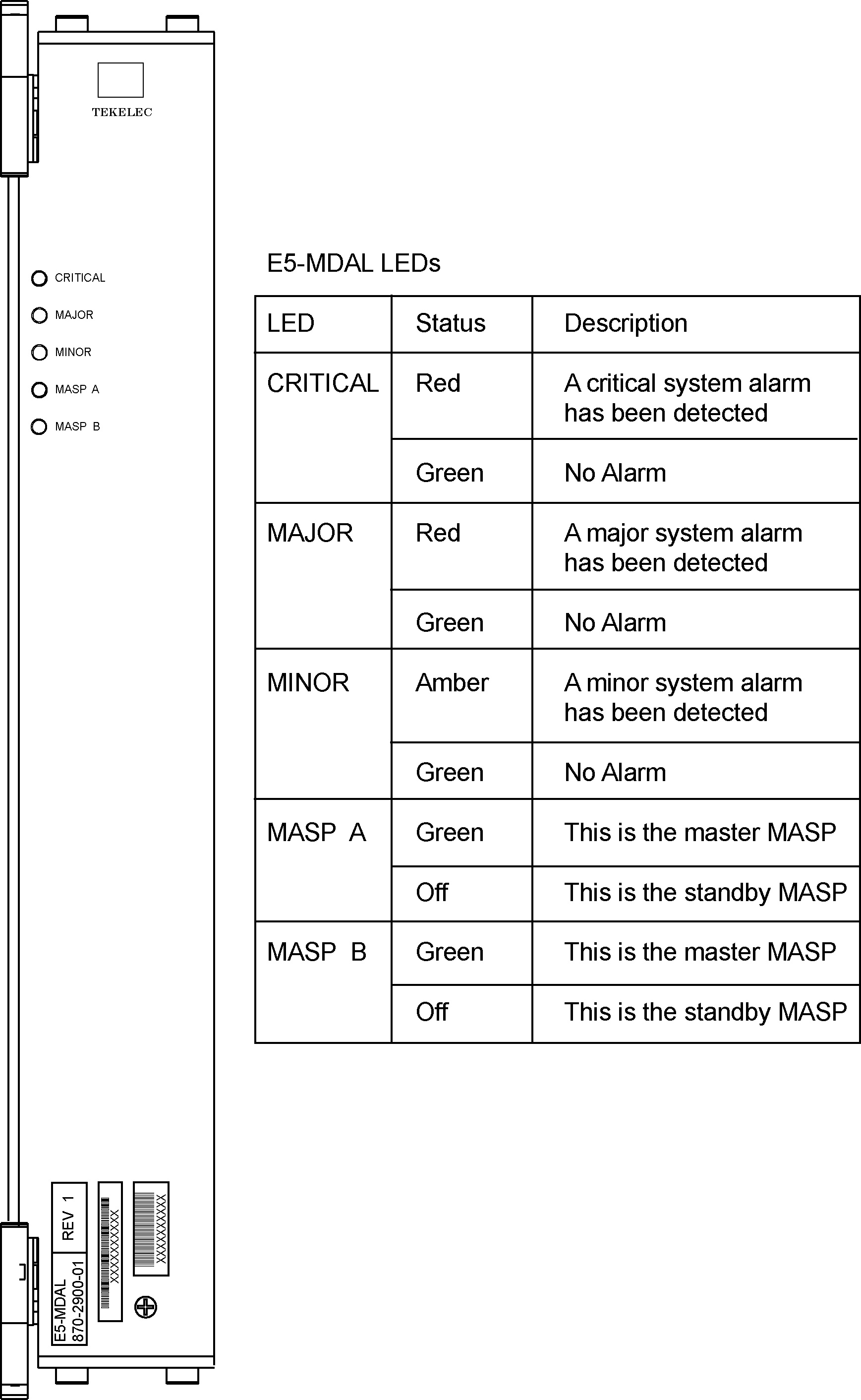
The E5-MDAL (Figure A-4) provides for external alarm indicators, such as bells, horns and lamp indicators.

  1. Remove the card from service as described in the section titled, Replacing a Card in the EAGLE.

    Note:

    Removing the E5-MDAL creates a critical alarm at the Remote Maintenance Center (RMC) as well as the local office.

Figure A-4 E5-MDAL LEDs

img/870-2903-xx_e5-mdal.jpg

A.5 HIPR2 Card Replacement

Use this procedure to remove a High-Speed Inter-processor Message Transport Packet Router 2 (HIPR2) card.

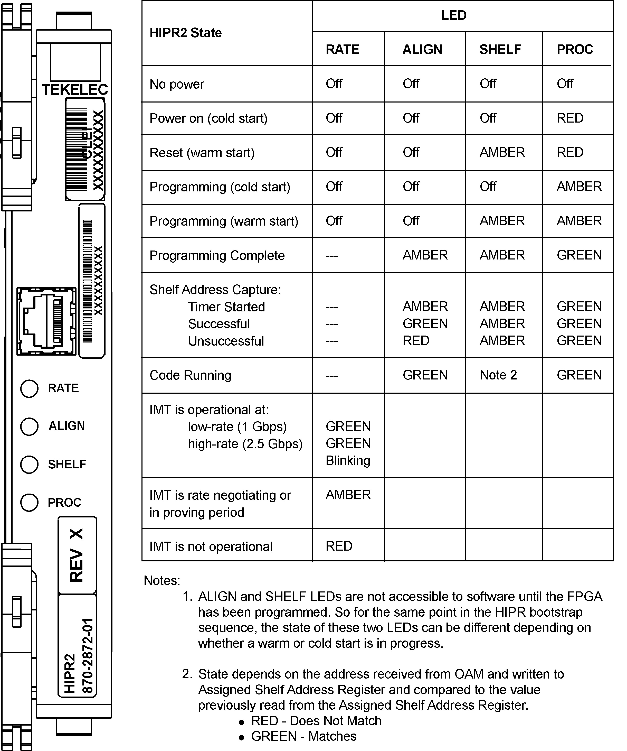
Each shelf contains two HIPR2 cards, one for each IMT bus, that provide continuity of the IMT bus signals even with failed or missing circuit modules. LEDs on the HIPR2 (Figure A-5) indicate connectivity to the IMT

  1. Enter the following command to verify the status of the IMT buses.
    rept-stat-imt

    warning:

    Be sure to inhibit the correct IMT bus. If you inhibit the wrong IMT bus and then remove the HIPR2, total nodal isolation will occur. Wait until the IMT has returned to IS-NR before replacing the other HIPR2.
    The following is an example of the possible output.
    
    RLGHNCXA03W 98-09-27 16:50:24 EST  EAGLE 34.0.0
     IMT   PST             SST        AST
      A    IS-NR           Active     -----
      ALARM STATUS       = No alarms
     IMT   PST             SST        AST
      B    IS-ANR          Fault      -----
      ALARM STATUS       = **  0108 Major IMT Failure Detected
    Command Completed.
    
  2. Enter the following command to inhibit the IMT bus associated with the HIPR2 being removed (top HIPR2 accesses bus A, bottom HIPR2 accesses bus B).
    rmv-imt:bus=x
    where x is the IMT bus to be inhibited.
  3. Remove the HIPR2, per the card replacement procedure described in the section titled Replacing a Card in the EAGLE.
    Place the new HIPR2 into its place. Be sure the revision numbers are compatible (if in doubt, contact My Oracle Support (MOS)).
  4. Enter the following command to restore the IMT bus.
    alw-imt:bus=x
    where x is the IMT bus inhibited.

    Note:

    If UAM 0002 is output, the newly installed HIPR2 card needs to be flashed.
  5. Enter the following command to determine if the newly replaced card's memory needs to be flashed:
    rept-stat-gpl:gpl=xxxxxx
    where xxxxxx is hipr2.
    Following is an example of a HIPR2 output:
    
    tekelecstp 09-07-09 16:53:23 EST  EAGLE5 41.1
    Output:
        GPL        CARD      RUNNING            APPROVED      TRIAL
        HIPR2      1109      128-021-000        128-021-000   128-021-000
        HIPR2      1110      128-021-000        128-021-000   128-021-000
    
        Command Completed.
    ;


    Note:

    Mismatched GPLs should occur only during upgrades or running a trial GPL.
  6. Examine the output from 5.
    • If the GPLs match, continue with 15.
    • If there is a GPL mismatch, continue with 7.
  7. Enter the following command to verify GPL Auditing is ON .
    chg-gpl:audit=on
  8. Enter the following command to load the GPL onto the HIPR2 card.
    init-flash:code=appr:loc=xxxx
    where xxxx is the card location newly replaced card.
    Following is an example of a HIPR2 output using card location 1309:
    
        RLGHNCXA03W  00-06-05  11:11:28 EDT  EAGLE 34.0.0
        FLASH Memory Downloading for card 1309 Started.
    ;
        RLGHNCXA03W  00-06-05  11:11:28 EDT EAGLE 34.0.0
        HIPR2 Downloading for card 1309 Complete.
    ;
        RLGHNCXA03W  00-06-05  11:11:28 EDT  EAGLE 34.0.0
        Command Completed.
    
  9. Enter either of the following commands to initialize the HIPR2.

    Caution:

    These commands boot the HIPR2 processor and bring down the respective IMT bus temporarily (approximately 10 seconds) until the HIPR2 card comes back into service.

    Enter either

    init-mux:bus=[a/b]

    or

    init-mux:loc=xxxx

    where xxxx is the card location used in 8.

    Note:

    Allow the card to run for 5 minutes before continuing.
  10. Enter the following command to activate the GPL loaded onto the HIPR2 card in 8:
    act-flash:loc=xxxx
    where xxxx is the card location used in 8.
    Following is an example of the output using card location 1309:
    
        RLGHNCXA03W  00-06-05  11:11:28 EDT  EAGLE 34.0.0
        FLASH Memory Activation for card 1309 Completed.
    ;
        RLGHNCXA03W  00-06-05  11:11:28 EDT  EAGLE 34.0.0
        Command Completed.
    
  11. Enter the following command to verify the approved GPLs match the running GPLs:
    rept-stat-gpl:gpl=hipr2
  12. If the GPLs match, continue with 15.
    If the GPLs do not match, continue with 13.
  13. Enter the following command determine which cards are in alarm condition (indicated by the acronym ALM in the rept-stat-gpl display):
    rept-stat-gpl
  14. Note which cards are in an alarm condition and, if in doubt, My Oracle Support (MOS).
  15. Enter the following command to verify that the HIPR2 card is in service and the IMT bus has been restored.
    rept-stat-imt
    
    RLGHNCXA03W 98-09-27 16:50:24 EST  EAGLE 34.0.0
     IMT   PST             SST        AST
      A    IS-NR           Active     -----
      ALARM STATUS       = No alarms
     IMT   PST             SST        AST
      B    IS-NR          Active     -----
      ALARM STATUS       = No alarms
    Command Completed.
    

Figure A-5 HIPR2 LEDs

img/870-2879-01_hipr2.jpg

A.6 Determine Card Changeout Time

Description

This procedure assists the customer in deciding if the card should be changed immediately or during the Maintenance Window.

  1. Replace the card immediately if any of the following conditions exist:
    • If there is only one link on the card
    • If there is no other in-service link on this card
    • If there is no other in-service link on this card
    • If any destination is prohibited by the current failure.
  2. Wait until the maintenance window to replace the card if all of the following conditions exist:
    • If the faulty link is not the only in-service link on the card
    • If deactivating the link will prohibit a destination
    • If no destination is prohibited by the current failure.

A.7 E5-ATM-B Card Replacement

This E5-ATM-B Module provides access to remote SS7, IP and other network elements, such as a Signaling Control Point (SCP). This card is equipped with an industry-standard ATM, or DS0 interface.

  1. Enter the following command to determine which links are serviced by this card:
    rept-stat-card:loc=xxxx

    Where xxxx is the card location. The following is an example of the possible output.

    
    RLGHNCXA03W 98-09-27 16:43:42 EST  EAGLE 34.0.0
    CARD  VERSION      TYPE    APPL      PST           SST       AST
    1201  021-002-000  LIMDS0  CCS7ITU   IS-NR         Active    -----
      ALARM STATUS      = *  0022 Clock B for card failed.
      IMT VERSION       = 021-001-000
      PROM VERSION      = 021-001-000
      IMT BUS A         = Conn
      IMT BUS B         = Fault
      SLK A PST         = IS-NR       LS=lsnsspn2  CLLI=-----------
      SLK B PST         = IS-NR       LS=lsnstpi   CLLI=-----------
      SCCP SERVICE CARD = 1212
    Command Completed.
    
  2. Refer to procedure to determine when to change the card.

    Note:

    The inh-slk command will be rejected if inhibiting the link would cause a DPC to become unavailable.
  3. Enter the following command to inhibit the links on both ports of this card (a and b).
    inh-slk:loc=xxxx:port=y

    Where xxxx location of the card from 1 and y is the port.

  4. Enter the following command to change the status of the link to out of service - maintenance disabled (oos-mt-dsbld).
    dact-slk:loc=xxxx:port=y

    Where xxxx location used in 3 and y are the ports used in 3.

  5. Enter the following command to ensure the signaling link status is oos-mt-dsbld (out of service - maintenance disabled).
    rept-stat-slk

    The following is an example of the possible output.

    
    RLGHNCXA03W 98-09-27 17:00:36 EST  EAGLE 34.0.0
    rept-stat-slk
    SLK    LSN          CLLI        PST          SST       AST
    1201,A lsnsspn2     ----------- OOS-MT-DSBLD Unava     ----
    1201,B lsnstpi      ----------- OOS-MT-DSBLD Unava     ----
    1202,A lsnstpn      ----------- IS-NR        Avail     ----
    1202,B lsnstpi      ----------- IS-NR        Avail     ----
    1203,A lsnstpa      ----------- IS-NR        Avail     ----
    1203,B lsnscpa      ----------- IS-NR        Avail     ----
    1205,A lsnscpi      ----------- IS-NR        Avail     ----
    1205,B lsnsspi1     ----------- IS-NR        Avail     ----
    1207,A lsnstpa      ----------- IS-NR        Avail     ----
    1207,B lsnsspa1     ----------- IS-NR        Avail     ----
    1211,A lsnstpn      ----------- IS-NR        Avail     ----
    1211,B lsnsspn1     ----------- IS-NR        Avail     ----
    Command Completed.
  6. Enter the following command to inhibit the card and disconnect it from the IMT bus.
    rmv-card:loc=xxxx

    Where xxxx location used in 3 and 4.

  7. Remove the card, per the card replacement procedure described in the section titled Replacing a Card in the EAGLE..
    Place the new card into its place. Be sure the revision numbers are compatible (if in doubt, contact the My Oracle Support (MOS)).
  8. Enter the following command to download generic program loads and database information:
    alw-card:loc=xxxx

    Where xxxx location used in 6.

  9. Enter the following command to determine which links are serviced by this card:
    rept-stat-card:loc=xxxx

    Where xxxx is the location of the replaced card.

    Note:

    The signaling link alarms will be present until the links are restored in 11.
  10. Examine the output from 9.
    Refer to Corrective Maintenance to clear any GPL related alarms on the newly replaced card before continuing.
  11. Enter the following command to return the links to service.
    Make sure this is done on all links:
    act-slk:loc=xxxx:port=y
    Where xxxx location used in 3 and 4 and y are the ports used in 3 and 4.
  12. Enter the following command to change the link status to IS-NR.
    Make sure this is done on both ports, a and b.
    unhb-slk:loc=xxxx:port=y
    Where xxxx location used in 3 and 4 and y are the ports used in 3 and 4.
  13. Enter the following command to verify the status of the card and its associated links:
    rept-stat-card:loc=xxxx

    Where xxxx is the card location. The following is an example of the possible output.

    
    RLGHNCXA03W 98-09-27 16:43:42 EST  EAGLE 34.0.0
    CARD  VERSION      TYPE    APPL      PST           SST       AST
    1201  024-002-000  LIMDS0  
    SS7ANSI
       IS-NR         Active    -----
      ALARM STATUS      = No Alarms.
      IMT VERSION       = 024-001-000
      PROM VERSION      = 024-001-000
      IMT BUS A         = Conn
      IMT BUS B         = Conn
      SLK A PST         = IS-NR       LS=lsnsspn2  CLLI=-----------
      SLK B PST         = IS-NR       LS=lsnstpi   CLLI=-----------
      SCCP SERVICE CARD = 1212
    Command Completed.
    
  14. Enter the following command to verify the links are properly aligned and are returned to full service:
    rept-stat-slk

    The following is an example of the possible output.

    RLGHNCXA03W 98-09-27 17:00:36 EST  EAGLE 34.0.0
    rept-stat-slk
    SLK    LSN          CLLI        PST          SST       AST
    1201,A lsnsspn2     ----------- IS-NR        Avail     ----
    1201,B lsnstpi      ----------- IS-NR        Avail     ----
    1202,A lsnstpn      ----------- IS-NR        Avail     ----
    1202,B lsnstpi      ----------- IS-NR        Avail     ----
    1203,A lsnstpa      ----------- IS-NR        Avail     ----
    1203,B lsnscpa      ----------- IS-NR        Avail     ----
    1205,A lsnscpi      ----------- IS-NR        Avail     ----
    1205,B lsnsspi1     ----------- IS-NR        Avail     ----
    1207,A lsnstpa      ----------- IS-NR        Avail     ----
    1207,B lsnsspa1     ----------- IS-NR        Avail     ----
    1211,A lsnstpn      ----------- IS-NR        Avail     ----
    1211,B lsnsspn1     ----------- IS-NR        Avail     ----
    Command Completed.

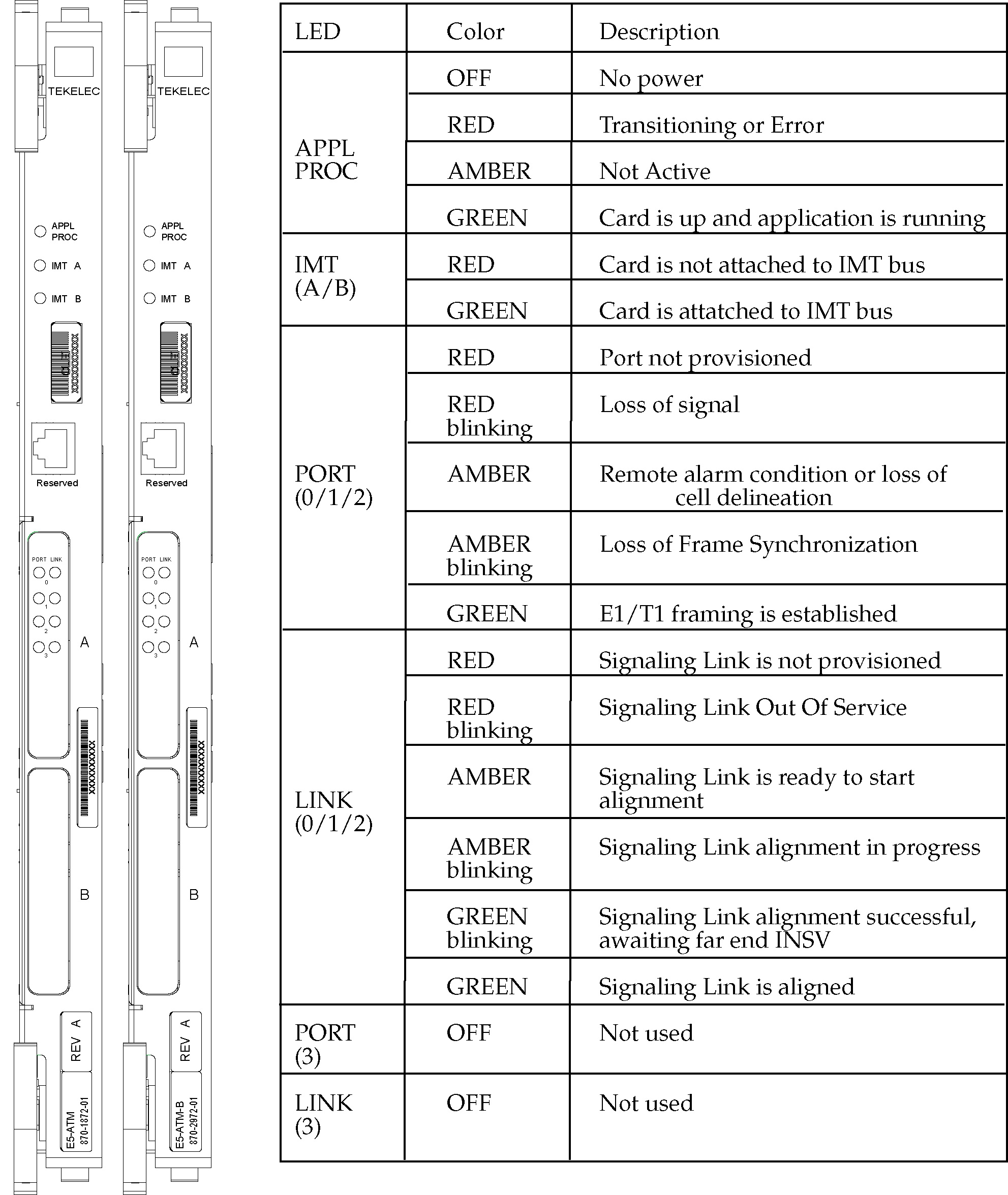
Figure A-6 E5-ATM-B LEDs

img/r_e5_atm-b_leds.jpg

A.8 SS7 and IP7 Card Replacement

This Link Interface Module (LIM) provides access to remote SS7, IP and other network elements, such as a Signaling Control Point (SCP). This card is equipped with an industry-standard ATM, or DS0 interface.

The types of Link Interface Modules (LIM)s currently available are:

  • LIM
  • The E5-E1/T1-B
  • SLIC
  1. Enter the following command to determine which links are serviced by this card:
    rept-stat-card:loc=xxxx

    Where xxxx is the card location. The following is an example of the possible output.

    
    RLGHNCXA03W 98-09-27 16:43:42 EST  EAGLE 34.0.0
    CARD  VERSION      TYPE    APPL      PST           SST       AST
    1201  021-002-000  LIMDS0  CCS7ITU   IS-NR         Active    -----
      ALARM STATUS      = *  0022 Clock B for card failed.
      IMT VERSION       = 021-001-000
      PROM VERSION      = 021-001-000
      IMT BUS A         = Conn
      IMT BUS B         = Fault
      SLK A PST         = IS-NR       LS=lsnsspn2  CLLI=-----------
      SLK B PST         = IS-NR       LS=lsnstpi   CLLI=-----------
      SCCP SERVICE CARD = 1212
    Command Completed.
    
  2. See Determine Card Changeout Time procedure to determine when to change the card.

    Note:

    The inh-slk command will be rejected if inhibiting the link would cause a DPC to become unavailable.
  3. Enter the following command to inhibit the links on both ports of this card (a and b).
    inh-slk:loc=xxxx:port=y

    Where xxxx location of the card from 1 and y is the port.

  4. Enter the following command to change the status of the link to out of service - maintenance disabled (oos-mt-dsbld).

    Enter the same location and ports from 3

    dact-slk:loc=xxxx:port=y

    Where xxxx location used in 3 and y are the ports used in 3 .

  5. Enter the following command to ensure the signaling link status is oos-mt-dsbld (out of service - maintenance disabled).
    rept-stat-slk

    The following is an example of the possible output.

    
    RLGHNCXA03W 98-09-27 17:00:36 EST  EAGLE 34.0.0
    rept-stat-slk
    SLK    LSN          CLLI        PST          SST       AST
    1201,A lsnsspn2     ----------- IS-NR        Avail     ----
    1201,B lsnstpi      ----------- OOS-MT-DSBLD LPBK      ----
    1202,A lsnstpn      ----------- IS-NR        Avail     ----
    1202,B lsnstpi      ----------- IS-NR        Avail     ----
    1203,A lsnstpa      ----------- IS-NR        Avail     ----
    1203,B lsnscpa      ----------- IS-NR        Avail     ----
    1205,A lsnscpi      ----------- IS-NR        Avail     ----
    1205,B lsnsspi1     ----------- IS-NR        Avail     ----
    1207,A lsnstpa      ----------- IS-NR        Avail     ----
    1207,B lsnsspa1     ----------- IS-NR        Avail     ----
    1211,A lsnstpn      ----------- IS-NR        Avail     ----
    1211,B lsnsspn1     ----------- IS-NR        Avail     ----
    Command Completed.
    
  6. Enter the following command to inhibit the card and disconnect it from the IMT bus.
    rmv-card:loc=xxxx

    Where xxxx location used in 3 and 4 .

  7. Remove the LIM/E5E1T1-B/SLIC, per the card replacement procedure described in the section titled Replacing a Card in the EAGLE..
    Place the new SS7LIM into its place. Be sure the revision numbers are compatible (if in doubt, contact the My Oracle Support (MOS) )
    ).
  8. Enter the following command to download generic program loads and database information from the E5-TDM card to the new LIM/E5E1T1-B/SLIC:
    alw-card:loc=xxxx

    Where xxxx location used in 6 .

  9. Enter the following command to determine which links are serviced by this card:
    rept-stat-card:loc=xxxx

    Where xxxx is the location of the replaced card.

    Note:

    The signaling link alarms will be present until the links are restored in 11.
  10. Examine the output from 9.
    See Corrective Maintenance to clear any GPL related alarms on the newly replaced card before continuing.
  11. Enter the following command to return the links to service.
    Make sure this is done on all links:
    act-slk:loc=xxxx:port=y
    Where xxxx location used in 3 and 4 and y are the ports used in 3 and 4.
  12. Enter the following command to change the link status to IS-NR.
    Make sure this is done on both ports, a and b.
    unhb-slk:loc=xxxx:port=y
    Where xxxx location used in 3 and 4 and y are the ports used in 3 and 4.
  13. Enter the following command to verify the status of the card and its associated links:
    rept-stat-card:loc=xxxx

    Where xxxx is the card location. The following is an example of the possible output.

    
    RLGHNCXA03W 98-09-27 16:43:42 EST  EAGLE 34.0.0
    CARD  VERSION      TYPE    APPL      PST           SST       AST
    1201  024-002-000  LIMDS0  
    SS7ANSI
       IS-NR         Active    -----
      ALARM STATUS      = No Alarms.
      IMT VERSION       = 024-001-000
      PROM VERSION      = 024-001-000
      IMT BUS A         = Conn
      IMT BUS B         = Conn
      SLK A PST         = IS-NR       LS=lsnsspn2  CLLI=-----------
      SLK B PST         = IS-NR       LS=lsnstpi   CLLI=-----------
      SCCP SERVICE CARD = 1212
    Command Completed.
    
  14. Enter the following command to verify the links are properly aligned and are returned to full service:
    rept-stat-slk

    The following is an example of the possible output.

    
    RLGHNCXA03W 98-09-27 17:00:36 EST  EAGLE 34.0.0
    rept-stat-slk
    SLK    LSN          CLLI        PST          SST       AST
    1201,A lsnsspn2     ----------- IS-NR        Avail     ----
    1201,B lsnstpi      ----------- OOS-MT-DSBLD LPBK      ----
    1202,A lsnstpn      ----------- IS-NR        Avail     ----
    1202,B lsnstpi      ----------- IS-NR        Avail     ----
    1203,A lsnstpa      ----------- IS-NR        Avail     ----
    1203,B lsnscpa      ----------- IS-NR        Avail     ----
    1205,A lsnscpi      ----------- IS-NR        Avail     ----
    1205,B lsnsspi1     ----------- IS-NR        Avail     ----
    1207,A lsnstpa      ----------- IS-NR        Avail     ----
    1207,B lsnsspa1     ----------- IS-NR        Avail     ----
    1211,A lsnstpn      ----------- IS-NR        Avail     ----
    1211,B lsnsspn1     ----------- IS-NR        Avail     ----
    Command Completed.
    

Figure A-7 DS0A-LIM LEDs


img/t_ss7_and_ip7_lim_mim_hcmim_and_mpl_card_replacement_maintmanual_fig1.jpg

A.9 E5-ENET-B Module

The term E5-ENET refers to the E5-ENET-B (P/N 870-2971-xx).

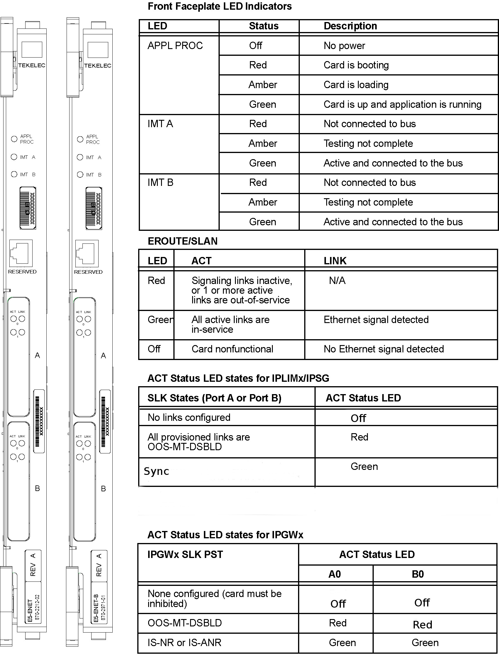
The E5-ENET-b module (refer to Figure A-8) can run different applications. Removal and replacement procedures differ depending on the application.

Note:

If this card is removed, the link supported by this card becomes out of service.

For removal and replacement procedures for a like-for-like card:

  • If the E5-ENET-B card is operating with signaling interfaces such as IPLIM, IPGW or IPSG, refer to IP SIGTRAN on E5-ENET-B.
  • If the E5-ENET-B card is operating with signaling interfaces such as EROUTE, refer to EROUTE on E5-ENET-B.

Figure A-8 E5-ENET-B LEDs
img/r_e5_enet-b_leds.jpg

A.9.1 IP SIGTRAN on E5-ENET-B

The term E5-ENET refers to the E5-ENET-B (P/N 870-2971-xx).

Use this procedure to remove and replace an E5-ENET-B card running an application such as IPLIM, IPLIMI, IPGWI, SS7IPGW, or IPSG, or SLIC running the IPSG application.

Note:

See the "Conversion of SLIC Cards" section in Database Administration - System Management for 32-bit to 64-bit conversion and vice versa.

See the "EAGLE Card Applications and GPLs" table in Database Administration - System Management for details on the flash and application GPLs that are run/required based on different card configurations.

  1. Enter the following command to determine which links are serviced by this card.
    rept-stat-card:loc=xxxx

    Where xxxx is the card location.

    The following is an example of the possible output.

        rlghncxa03w 06-06-01 16:43:42 EST  EAGLE 46.6.0.0
        CARD   VERSION      TYPE      GPL        PST            SST        AST
        1301   082-000-039  E5-ENET      IPLHC      IS-NR          Active     -----
          ALARM STATUS       = No Alarms.
          BLMCAP GPL version = 126-002-000
          IMT BUS A           = Conn
          IMT BUS B           = Disc
          SIGNALING LINK STATUS
              SLK    PST                LS            CLLI          E5IS
              A      IS-NR              ls1m2pa       -----------   INACTIVE
              B      OOS-MT             ls1m2pa       -----------   INACTIVE
              A1     OOS-MT             ls1m2pa       -----------   INACTIVE
              B1     OOS-MT             ls1m2pa       -----------   INACTIVE
              A2     OOS-MT             ls1m2pa       -----------   INACTIVE
              B2     OOS-MT             ls1m2pa       -----------   INACTIVE
              A3     OOS-MT             ls1m2pa       -----------   INACTIVE
              B3     OOS-MT             ls1m2pa       -----------   INACTIVE
    
        Command Completed.
    ;
  2. Refer to Determine Card Changeout Time procedure to determine when to change the card.
  3. Enter the following command to inhibit the links on both ports of this card (a and b):
    inh-slk:loc=xxxx:port=y

    Note:

    This step is not applicable for IPSG-M3UA and IPGW links.

    Where xxxx is the location of the card and y is the port.

    Note:

    The inh-slk command will be rejected if inhibiting the link would cause a DPC to become unavailable.

    The following is an example of the possible output.

        rlghncxa03w 05-01-07 11:11:28 EST  EAGLE5 33.0.0
        Inhibit Link message sent to card
    ;
  4. Enter the following command to change the status of the link to out of service - maintenance disabled (oos-mt-dsbld).
    dact-slk:loc=xxxx:port=y

    Where xxxx is the card location and y is the port used.

    The following is an example of the possible output.

        rlghncxa03w 04-01-07 11:11:28 EST  EAGLE5 33.0.0
        Deactivate Link message sent to card
    ;
  5. Enter the following command to ensure the signaling link status is oos-mt-dsbld (out of service - maintenance disabled).
    rept-stat-slk

    The following is an example of the possible output.

    
    RLGHNCXA03W 98-09-27 17:00:36 EST  EAGLE 34.0.0
    rept-stat-slk
    SLK    LSN          CLLI        PST          SST       AST
    1201,A lsnsspn2     ----------- IS-NR        Avail     ----
    1201,B lsnstpi      ----------- OOS-MT-DSBLD LPBK      ----
    1202,A lsnstpn      ----------- IS-NR        Avail     ----
    1202,B lsnstpi      ----------- IS-NR        Avail     ----
    1203,A lsnstpa      ----------- IS-NR        Avail     ----
    1203,B lsnscpa      ----------- IS-NR        Avail     ----
    1205,A lsnscpi      ----------- IS-NR        Avail     ----
    1205,B lsnsspi1     ----------- IS-NR        Avail     ----
    1207,A lsnstpa      ----------- IS-NR        Avail     ----
    1207,B lsnsspa1     ----------- IS-NR        Avail     ----
    1211,A lsnstpn      ----------- IS-NR        Avail     ----
    1211,B lsnsspn1     ----------- IS-NR        Avail     ----
    Command Completed.
    
  6. Enter the following command to inhibit the card and disconnect it from the IMT bus.
    rmv-card:loc=xxxx

    Where xxxx is the location.

    The following is an example of the possible output.

        rlghncxa03w 04-01-07 11:11:28 EST  EAGLE 31.3.0
        Card has been inhibited.
    ;
  7. Remove the E5-ENET card per the card replacement procedure described in the section titled Replacing a Card in the EAGLE.
    Place the new E5-ENET card into its place. Be sure the revision numbers are compatible (if in doubt, contact My Oracle Support (MOS)).
  8. Enter the following command to verify GPL versions:

    rept-stat-gpl:loc=xxxx,

    Where xxxx is the location of the replaced card.

    The following is an example of the possible output:

    eaglestp YY-MM-DD hh:mm:ss TTTT EAGLE XX.x.x-YY.yy.y 
        GPL        CARD      RUNNING            APPROVED      TRIAL
        IPSG       XXXX     -----------      XXX-XXX-XXX   XXX-XXX-XXX
               ZZZZZZ       YYY-YYY-YYY      YYY-YYY-YYY   YYY-YYY-YYY
    
        Command Completed.
    

    Where ZZZZZZ is the Flash GPL name (BLMCAP, BLSLC32, for example). If the Flash GPL is not getting displayed, then wait for the card to be back on the IMT and run the command again.

  9. If replacing an E5-ENETB card with a SLIC card, change the card type to SLIC using the chg-card:type=slic:loc=xxxx command,

    Where xxxx is the location of the replaced card.

  10. Examine the output from
    Refer to Corrective Maintenance to clear any Flash GPL related alarms on the newly replaced card before continuing.
  11. Enter the following command to put the card back into service:

    alw-card:loc=xxxx

    where xxxx is the card location used in 6

    The following is an example of a possible output:

    Command Accepted - Processing
    eagle3 02-01-18 18:02:20 EST EAGLE5 41.2.0-62.69.65
    alw-card:loc=1112
    Command entered at terminal #1.
    ;
    eagle3 02-01-18 18:02:20 EST EAGLE5 41.2.0-62.69.65
    Card has been allowed.
    ;
    eagle3 02-01-18 18:02:20 EST EAGLE5 41.2.0-62.69.65
    Command Completed.
    ;
    
  12. Enter the following command to return the links to service.
    act-slk:loc=xxxx:port=y

    Where xxxx is the location and y are the ports used in 3 and 4.

    Make sure this is done on all links.

    The following is an example of the possible output.

        tekelecstp 05-01-21 17:00:36 EST  EAGLE5 33.0.0
        Activate Link message sent to card
    ;
  13. Enter the following command to change the link status to IS-NR:
    unhb-slk:loc=xxxx:port=y

    Note:

    This step is not applicable for IPSG-M3UA and IPGW links.

    Make sure this is done on both ports, a and b.

    Where xxxx is the location used in 3 and 4 and y are the ports used in the same steps, respectively.

    The following is an example of the possible output.

        rlghncxa03w 03-03-23 13:20:59 EST  EAGLE 31.3.0
        Allow Link message sent to card
    ;
  14. Enter the following command to verify the status of the card and its associated links.
    rept-stat-card:loc=xxxx

    Where xxxx is the card location.

    The following is an example of the possible output.

        rlghncxa03w 06-06-01 16:43:42 EST  EAGLE 46.6.0.0
        CARD   VERSION      TYPE      GPL        PST            SST        AST
        1301   082-000-039  E5-ENET      IPLHC      IS-NR          Active     -----
          ALARM STATUS       = No Alarms.
          BLMCAP GPL version = 126-002-000
          IMT BUS A           = Conn
          IMT BUS B           = Disc
          SIGNALING LINK STATUS
              SLK    PST                LS            CLLI          E5IS
              A      IS-NR              ls1m2pa       -----------   INACTIVE
              B      OOS-MT             ls1m2pa       -----------   INACTIVE
              A1     OOS-MT             ls1m2pa       -----------   INACTIVE
              B1     OOS-MT             ls1m2pa       -----------   INACTIVE
              A2     OOS-MT             ls1m2pa       -----------   INACTIVE
              B2     OOS-MT             ls1m2pa       -----------   INACTIVE
              A3     OOS-MT             ls1m2pa       -----------   INACTIVE
              B3     OOS-MT             ls1m2pa       -----------   INACTIVE
    
        Command Completed.
    ;
  15. Enter the following command to verify the links are properly aligned and are returned to full service.
    rept-stat-slk

    The following is an example of the possible output.

    
    RLGHNCXA03W 98-09-27 17:00:36 EST  EAGLE 34.0.0
    rept-stat-slk
    SLK    LSN          CLLI        PST          SST       AST
    1201,A lsnsspn2     ----------- IS-NR        Avail     ----
    1201,B lsnstpi      ----------- OOS-MT-DSBLD LPBK      ----
    1202,A lsnstpn      ----------- IS-NR        Avail     ----
    1202,B lsnstpi      ----------- IS-NR        Avail     ----
    1203,A lsnstpa      ----------- IS-NR        Avail     ----
    1203,B lsnscpa      ----------- IS-NR        Avail     ----
    1205,A lsnscpi      ----------- IS-NR        Avail     ----
    1205,B lsnsspi1     ----------- IS-NR        Avail     ----
    1207,A lsnstpa      ----------- IS-NR        Avail     ----
    1207,B lsnsspa1     ----------- IS-NR        Avail     ----
    1211,A lsnstpn      ----------- IS-NR        Avail     ----
    1211,B lsnsspn1     ----------- IS-NR        Avail     ----
    Command Completed.
    
    Procedure complete.

A.9.2 EROUTE on E5-ENET-B

The term E5-ENET refers to either the E5-ENET-B (P/N 870-2971-xx).

Use this procedure to remove and replace an E5-ENET-B card running an application such as EROUTE.

  1. Enter the following command to determine what TCP/IP data links are configured.
    rept-stat-card
    The following is an example of a possible output.
    
        rlghncxa03w 10-01-09 16:35:57 IST  EAGLE 46.0.0
    
        CARD   VERSION      TYPE      GPL        PST            SST       AST
        1101   125-020-000  TSM       GLS        IS-NR          Active    -----
        1102   128-002-000  LIMATM    ATMHC      IS-NR          Active    -----
        1103   125-020-000  E5SM4G    SCCPHC     IS-NR          Active    -----
        1105   125-020-000  E5SM4G    SCCPHC     IS-NR          Active    -----
        1106   130-001-000  TSM       GLSHC      IS-NR          Active    -----
        1109   125-020-000  HIPR2     HIPR2      IS-NR          Active    -----
        1110   125-020-000  HIPR2     HIPR2      IS-NR          Active    -----
        1111   125-020-000  IPSM      IPS        IS-NR          Active    -----
        1112   125-020-000  EDSM      MCP        IS-NR          Active    -----
        1113   070-019-002  E5MCAP    OAMHC      IS-NR          Standby   -----
        1114   -----------  E5TDM                IS-NR          Active    -----
        1115   070-019-002  E5MCAP    OAMHC      IS-NR          Active    -----
        1116   -----------  E5TDM                IS-NR          Active    -----
        1117   -----------  E5MDAL               IS-NR          Active    -----
        1201   125-020-000  LIMDS0    SS7ANSI    IS-NR          Active    -----
        1202   -----------  LIMCH     SS7ANSI    OOS-MT-DSBLD   Manual    -----
        1203   125-020-000  LIMCH     SS7ANSI    IS-NR          Active    -----
        1209   125-020-000  HIPR2     HIPR2      IS-NR          Active    -----
        1210   125-020-000  HIPR2     HIPR2      IS-NR          Active    -----
        1211   125-020-000  LIMATM    ATMANSI    IS-NR          Active    -----
        1213   125-020-000  LIME1ATM  ATMITU     IS-NR          Active    -----
        1301   048-019-022  LIME1     SS7ANSI    IS-NR          Active    -----
        1303   125-022-000  LIME1     SS7ANSI    IS-NR          Active    -----
        1305   125-022-000  LIME1     CCS7ITU    IS-NR          Active    -----
        1309   125-017-000  HIPR2     HIPR2      IS-NR          Active    -----
        1310   125-017-000  HIPR2     HIPR2      IS-NR          Active    -----
        2101   104-002-000  LIMV35    CCS7ITU    IS-NR          Active    -----
        2103   128-018-000  DCM       IPLHC      IS-NR          Active    -----
        2107   104-001-000  LIMCH     CCS7ITU    IS-NR          Active    -----
        2109   128-022-000  HIPR2     HIPR2      IS-NR          Active    -----
        2110   128-022-000  HIPR2     HIPR2      IS-NR          Active    -----
        2111   128-018-000  STC       ERTHC      IS-NR          Active    -----
        1213   053-000-058  E5ENET    IPSG       IS-NR          Active    -----
        Command Completed.
    ;
  2. Enter the following command to determine the status of the TCP/IP data link assigned to the card to be replaced.
    rept-stat-dlk
    The following is an example of the possible output.
    
        rlghncxa03w 10-01-27 17:00:36 EST  EAGLE 42.0.0
        DLK             PST          SST       AST
        1104            IS-NR        Active    ----
        1206            IS-NR        Active    ALMINH
        Command Completed.
    ;
  3. Note the status of the TCP/IP data link.
    • If the link is out of service - maintenance disabled (OOS-MT-DSBLD), go to 5.
    • If the link is not out of service, go to the next step.
  4. Enter the following command to change the status of the TCP/IP data link to OOS-MT-DSBLD.
    canc-dlk:loc=xxxx

    Where xxxx is the card location.

    The following is an example of a possible output.
    
        rlghncxa03w 04-01-27 17:00:36 EST  EAGLE 31.3.0
        Deactivate Link message sent to card.
        Command Completed.
    ;
  5. Enter the following command to inhibit the card and disconnect it from the IMT bus.
    rmv-card:loc=xxxx
    Where xxxx is the card location.

    Note:

    If this is the last type ENET card in the system, the :force=yes parameter must be used with this command.
    The following is an example of a possible output.
    
        rlghncxa03w 04-01-07 11:11:28 EST  EAGLE 31.3.0
        Card has been inhibited.
    ;
  6. Remove the E5-ENET, per the card replacement procedure described in the section titled Replacing a Card in the EAGLE.
    Place the new E5-ENET-B into its place. Be sure the revision numbers are compatible (if in doubt, contact My Oracle Support (MOS)).
  7. Enter the following command to put the new E5-ENET-B card back into service and connect it to the IMT bus.
    alw-card:loc=xxxx

    where xxxx = card location.

    The following is an example of a possible output.
        rlghncxa03w 04-01-07 11:11:28 EST  EAGLE 31.3.0
        Card has been allowed.
    ;
  8. Enter the following command to return the TCP/IP data link to service.
    act-dlk:loc=xxxx

    where xxxx is the card location.

    The following is an example of a possible output.
        rlghncxa03w 04-01-17:00:36 EST  EAGLE 31.3.0
        Activate Link message sent to card.
        Command Completed.
    ;
  9. Enter the following command to verify the status of the card and its associated TCP/IP data link.
    rept-stat-card
    The following is an example of a possible output.
    
        rlghncxa03w 10-01-09 16:35:57 IST  EAGLE 46.0.0
    
        CARD   VERSION      TYPE      GPL        PST            SST       AST
        1101   125-020-000  TSM       GLS        IS-NR          Active    -----
        1102   128-002-000  LIMATM    ATMHC      IS-NR          Active    -----
        1103   125-020-000  E5SM4G    SCCPHC     IS-NR          Active    -----
        1105   125-020-000  E5SM4G    SCCPHC     IS-NR          Active    -----
        1106   130-001-000  TSM       GLSHC      IS-NR          Active    -----
        1109   125-020-000  HIPR2     HIPR2      IS-NR          Active    -----
        1110   125-020-000  HIPR2     HIPR2      IS-NR          Active    -----
        1111   125-020-000  IPSM      IPS        IS-NR          Active    -----
        1112   125-020-000  EDSM      MCP        IS-NR          Active    -----
        1113   070-019-002  E5MCAP    OAMHC      IS-NR          Standby   -----
        1114   -----------  E5TDM                IS-NR          Active    -----
        1115   070-019-002  E5MCAP    OAMHC      IS-NR          Active    -----
        1116   -----------  E5TDM                IS-NR          Active    -----
        1117   -----------  E5MDAL               IS-NR          Active    -----
        1201   125-020-000  LIMDS0    SS7ANSI    IS-NR          Active    -----
        1202   -----------  LIMCH     SS7ANSI    OOS-MT-DSBLD   Manual    -----
        1203   125-020-000  LIMCH     SS7ANSI    IS-NR          Active    -----
        1209   125-020-000  HIPR2     HIPR2      IS-NR          Active    -----
        1210   125-020-000  HIPR2     HIPR2      IS-NR          Active    -----
        1211   125-020-000  LIMATM    ATMANSI    IS-NR          Active    -----
        1213   125-020-000  LIME1ATM  ATMITU     IS-NR          Active    -----
        1301   048-019-022  LIME1     SS7ANSI    IS-NR          Active    -----
        1303   125-022-000  LIME1     SS7ANSI    IS-NR          Active    -----
        1305   125-022-000  LIME1     CCS7ITU    IS-NR          Active    -----
        1309   125-017-000  HIPR2     HIPR2      IS-NR          Active    -----
        1310   125-017-000  HIPR2     HIPR2      IS-NR          Active    -----
        2101   104-002-000  LIMV35    CCS7ITU    IS-NR          Active    -----
        2103   128-018-000  DCM       IPLHC      IS-NR          Active    -----
        2107   104-001-000  LIMCH     CCS7ITU    IS-NR          Active    -----
        2109   128-022-000  HIPR2     HIPR2      IS-NR          Active    -----
        2110   128-022-000  HIPR2     HIPR2      IS-NR          Active    -----
        2111   128-018-000  STC       ERTHC      IS-NR          Active    -----
        1213   053-000-058  E5ENET    IPSG       IS-NR          Active    -----
        Command Completed.
    ;
  10. Enter the following command to verify that the TCP/IP data link has returned to full service.
    rept-stat-dlk
    The following is an example of the possible output.
    
        rlghncxa03w 10-01-27 17:00:36 EST  EAGLE 42.0.0
        DLK             PST          SST       AST
        1104            IS-NR        Active    ----
        1206            IS-NR        Active    ALMINH
        Command Completed.
    ;
  11. Procedure is complete.

A.10 Database Services Module (DSM)

Description

DSM (Figure A-10) cards are related to the TSM/DCM family, but differ by having an AMD K-6 processor and from 1 to 4 GB of memory on an applique board. The DSM card also differs from the TSM cards by having ethernet ports. The DSMs run a version of the SCCP application that has been ported to the VxWorks OS. To differentiate the DSM-VxWorks-SCCP from the SCCP that runs on the TSM cards, the DSM version has been named VSCCP. The extra memory is required to hold a copy of the RTDB. Ethernet ports are required to connect to the EPAP to download the RTDB. Multiple DSMs are used to provide a means of load balancing in high-traffic situations. Each DSM contains an identical database. Furthermore, the DSM RTDBs need to be identical to the one maintained by the EPAPs.

Note:

If there are provisioning scripts, such as LARG data, the DSM replacement activity should be coordinated with the DB/Admin operations to avoid extended provision otherwise RADB resets may occur.
  1. Enter the following command to determine which cards are in service.
    rept-stat-card:loc=xxxx

    Where xxxx is the DSM card location.

    This will indicate which link interface modules (LIMs) will be affected by removal of the DSM card.
  2. Enter the following command to determine the number of DSM cards in service providing GTT.
    rept-stat-sccp
    The following is an example of the possible output.
    
    RLGHNCXA03W  98-02-04 15:10:19 EST EAGLE 34.0.0
    SCCP SUBSYSTEM REPORT IS-NR          Active      -----
    GSM  SUBSYSTEM REPORT IS-NR          Active      -----
    INP  SUBSYSTEM REPORT IS-ANR         Restricted  -----
         ASSUMING MATE'S LOAD
         INPQS: SSN STATUS = Allowed     MATE SSN STATUS  = Prohibited
      
    SCCP Cards Configured= 4  Cards IS-NR= 2  Capacity Threshold = 100%
    CARD   VERSION      PST          SST          AST       MSU USAGE  CPU USAGE
        ------------------------------------------------------------------------------
    1212   103-001-000  IS-NR        Active       ALMINH       45%         30%
    1301 P 103-001-000  IS-NR        Active       ------       35%         40%
    1305   -----------  OOS-MT       Isolated     ------        0%          0%
    2112   -----------  OOS-MT-DSBLD Manual       ------        0%          0%
        ------------------------------------------------------------------------------
    SCCP Service Average MSU Capacity = 40%       Average CPU Capacity = 35%
    AVERAGE CPU USAGE PER SERVICE: 
      GTT   = 15%  GFLEX =  5%  GPORT = 10%
      INPMR =  2%  INPQS =  3%   
    TOTAL SERVICE STATISTICS:  
      SERVICE    SUCCESS    ERRORS    WARNINGS    FORWARD TO GTT    TOTAL
      GTT:          1995         5           -                 -     2000  
      GFLEX:         500         1           4                10      515
      GPORT:         800         0           2                 3      805
      INPMR:          50         5           0                15       70
      INPQS:         499         1           -                 -      500
    Command Completed.
    

    Caution:

    Inhibiting/removing all DSM cards at one time will cause an SCCP nodal outage.
  3. Enter the following command to remove the DSM card from service.

    Caution:

    Removing/inhibiting the last IS-NR DSM card will cause an SCCP outage on the affected node. Before removing the last IS-NR DSMP card from service, ensure the mated STP DSM cards are IS-NR and capable of supporting the rerouted SCCP traffic.
    rmv-card:loc=xxxx

    Where xxxx is the DSM card location.

    If this is the last DSM card in service, the:force=yes parameter must be specified.
  4. Remove the DSM card, per the card replacement procedure described in the section titled Replacing a Card in the EAGLE.
    Place the new DSM card into its place. Be sure the revision numbers are compatible (if in doubt, My Oracle Support (MOS)).
  5. Enter the following command to return the DSM card into service.
    alw-card:loc=xxxx

    Where xxxx is the DSM card location.

    This causes the MASP to begin downloading tables to the new DSM card. When the card has been successfully loaded (there will be a response on the terminal that downloading is complete). This can take up to 4 hours.
  6. Enter the following command to verify the card is operational and providing SCCP services.
    rept-stat-sccp
    The following is an example of the possible output.
    
    RLGHNCXA03W  98-02-04 15:10:19 EST EAGLE 34.0.0
    SCCP SUBSYSTEM REPORT IS-NR          Active      -----
    GSM  SUBSYSTEM REPORT IS-NR          Active      -----
    INP  SUBSYSTEM REPORT IS-ANR         Restricted  -----
         ASSUMING MATE'S LOAD
         INPQS: SSN STATUS = Allowed     MATE SSN STATUS  = Prohibited
      
    SCCP Cards Configured= 4  Cards IS-NR= 2  Capacity Threshold = 100%
    CARD   VERSION      PST          SST          AST       MSU USAGE  CPU USAGE
        ------------------------------------------------------------------------------
    1212   103-001-000  IS-NR        Active       ALMINH       45%         30%
    1301 P 103-001-000  IS-NR        Active       ------       35%         40%
    1305   -----------  OOS-MT       Isolated     ------        0%          0%
    2112   -----------  OOS-MT-DSBLD Manual       ------        0%          0%
        ------------------------------------------------------------------------------
    SCCP Service Average MSU Capacity = 40%       Average CPU Capacity = 35%
    AVERAGE CPU USAGE PER SERVICE: 
      GTT   = 15%  GFLEX =  5%  GPORT = 10%
      INPMR =  2%  INPQS =  3%   
    TOTAL SERVICE STATISTICS:  
      SERVICE    SUCCESS    ERRORS    WARNINGS    FORWARD TO GTT    TOTAL
      GTT:          1995         5           -                 -     2000  
      GFLEX:         500         1           4                10      515
      GPORT:         800         0           2                 3      805
      INPMR:          50         5           0                15       70
      INPQS:         499         1           -                 -      500
    Command Completed.
    

A.11 E5-SM8G-B Card Replacement

The term E5-SM4G refers to either the E5-SM8G-B (P/N 870-2990-01).

The E5-SM8G-B card is a database service module (DSM) designed to operate in the EAGLE shelf. The E5-SM8G-B is a replacement for the DSM card (P/N 870-1984-xx) and the E5-SM4G card. Ethernet ports connect to the EPAP to download the RTDB. Multiple cards are used to provide a means of load balancing in high-traffic situations. Each card contains an identical database. Furthermore, the E5-SM4G RTDBs need to be identical to the one maintained by the EPAPs.

Note:

See the "Conversion of SM8G-B Cards" section in Database Administration - System Management for 32-bit to 64-bit conversion and vice versa.

Note:

If there are provisioning scripts, such as LARG data, the E5-SM4G replacement activity should be coordinated with the DB/Admin operations to avoid extended provision otherwise RADB resets may occur.
  1. Enter the following command to determine which cards are in service. This will indicate which link interface modules (LIMs) will be affected by removal of the E5-SM4G card.
    rept-stat-card:loc=xxxx

    Where xxxx is the E5-SM4G card location.

  2. Enter the following command to determine the number of E5-SM4G cards in service providing GTT.
    rept-stat-sccp
    The following is an example of the possible output.
    RLGHNCXA03W  98-02-04 15:10:19 EST EAGLE 34.0.0
    SCCP SUBSYSTEM REPORT IS-NR          Active      -----
    GSM  SUBSYSTEM REPORT IS-NR          Active      -----
    INP  SUBSYSTEM REPORT IS-ANR         Restricted  -----
         ASSUMING MATE'S LOAD
         INPQS: SSN STATUS = Allowed     MATE SSN STATUS  = Prohibited
      
    SCCP Cards Configured= 4  Cards IS-NR= 2  Capacity Threshold = 100%
    CARD   VERSION      PST          SST          AST       MSU USAGE  CPU USAGE
        ------------------------------------------------------------------------------
    1212   103-001-000  IS-NR        Active       ALMINH       45%         30%
    1301 P 103-001-000  IS-NR        Active       ------       35%         40%
    1305   -----------  OOS-MT       Isolated     ------        0%          0%
    2112   -----------  OOS-MT-DSBLD Manual       ------        0%          0%
        ------------------------------------------------------------------------------
    SCCP Service Average MSU Capacity = 40%       Average CPU Capacity = 35%
    
    AVERAGE CPU USAGE PER SERVICE: 
      GTT   = 15%  GFLEX =  5%  GPORT = 10%
      INPMR =  2%  INPQS =  3%   
    
    TOTAL SERVICE STATISTICS:  
      SERVICE    SUCCESS    ERRORS    WARNINGS    FORWARD TO GTT    TOTAL
      GTT:          1995         5           -                 -     2000  
      GFLEX:         500         1           4                10      515
      GPORT:         800         0           2                 3      805
      INPMR:          50         5           0                15       70
      INPQS:         499         1           -                 -      500
    
    Command Completed.

    Caution:

    Inhibiting/removing all E5-SM4G cards at one time will cause an SCCP nodal outage.
  3. Enter the following command to remove the E5-SM4G card from service. If this is the last E5-SM4G card in service, the :force=yes parameter must be specified.

    Caution:

    Removing/inhibiting the last IS-NR E5-SM4G card will cause an SCCP outage on the affected node. Before removing the last IS-NR E5-SM4G card from service, ensure the mated STP E5-SM4G cards are IS-NR and capable of supporting the rerouted SCCP traffic.
    rmv-card:loc=xxxx
    Where xxxx is the E5-SM4G card location.
  4. Remove the E5-SM4G card, per the card replacement procedure described in Replacing a Card in the EAGLE. Place the new E5-SM8G-B card into its place. Be sure the revision numbers are compatible (if in doubt, contact the My Oracle Support (MOS)).
  5. Enter the following command Use the alw-card command to return the E5-SM4G card into service. This causes the MASP to begin downloading tables to the new E5-SM8G-B card.
    alw-card:loc=xxxx
    Where xxxx is the E5-SM8G-B card location.
    This causes the MASP to begin downloading tables to the new E5-SM8G-B card. When the card has been successfully loaded (there will be a response on the terminal that downloading is complete). This can take up to 4 hours.
  6. Enter the following command to verify the card is operational and providing SCCP services.
    rept-stat-sccp
    The following is an example of the possible output.
    RLGHNCXA03W  98-02-04 15:10:19 EST EAGLE 34.0.0
    SCCP SUBSYSTEM REPORT IS-NR          Active      -----
    GSM  SUBSYSTEM REPORT IS-NR          Active      -----
    INP  SUBSYSTEM REPORT IS-ANR         Restricted  -----
         ASSUMING MATE'S LOAD
         INPQS: SSN STATUS = Allowed     MATE SSN STATUS  = Prohibited
      
    SCCP Cards Configured= 4  Cards IS-NR= 2  Capacity Threshold = 100%
    CARD   VERSION      PST          SST          AST       MSU USAGE  CPU USAGE
        ------------------------------------------------------------------------------
    1212   103-001-000  IS-NR        Active       ALMINH       45%         30%
    1301 P 103-001-000  IS-NR        Active       ------       35%         40%
    1305   -----------  OOS-MT       Isolated     ------        0%          0%
    2112   -----------  OOS-MT-DSBLD Manual       ------        0%          0%
        ------------------------------------------------------------------------------
    SCCP Service Average MSU Capacity = 40%       Average CPU Capacity = 35%
    
    AVERAGE CPU USAGE PER SERVICE: 
      GTT   = 15%  GFLEX =  5%  GPORT = 10%
      INPMR =  2%  INPQS =  3%   
    
    TOTAL SERVICE STATISTICS:  
      SERVICE    SUCCESS    ERRORS    WARNINGS    FORWARD TO GTT    TOTAL
      GTT:          1995         5           -                 -     2000  
      GFLEX:         500         1           4                10      515
      GPORT:         800         0           2                 3      805
      INPMR:          50         5           0                15       70
      INPQS:         499         1           -                 -      500
    
    Command Completed.

    Figure A-9 E5-SM8G-B LEDs

    img/r_e5_sm4g-b_leds.jpg

A.12 E5-ENET-B Card Replacement

This procedure if for the replacement of E5-ENET-B (P/N 870-2971-xx) cards running IPS. The E5-ENET-B can be exchanged with IPSM cards running IPS, without any changes in provisioning information.

When command ENT-CARD is issued for IPSHC, the APPL parameter would be specified as IPS and TYPE would be specified as IPSM. The determination of actual GPL that needs to be loaded on the card is made by OAM based on the hardware board identification provided by the card itself .

  1. Enter the following command to retrieve the terminal types and port numbers:
    rtrv-trm
    The following is an example of the possible display of the terminal settings with the IP User Interface feature enabled and three IPSM cards equipped.
        rlghncxa03w  03-11-01 16:02:08 EST  EAGLE 31.3.0
        TRM   TYPE    COMM        FC    TMOUT MXINV DURAL
        1     VT320   9600 -7-E-1 SW    0     5     00:01:00
        2     VT320   9600 -7-E-1 SW    0     5     00:01:00
        3     VT320   9600 -7-E-1 SW    0     5     00:01:00
        4     KSR     9600 -7-E-1 SW    0     5     00:01:00
        5     NONE    9600 -7-E-1 SW    30    5     00:01:00
        6     NONE    9600 -7-E-1 SW    30    5     00:01:00
        7     NONE    9600 -7-E-1 SW    30    5     00:01:00
        8     NONE    9600 -7-E-1 SW    30    5     00:01:00
        9     VT320   9600 -7-E-1 SW    0     5     00:01:00
        10    VT320   9600 -7-E-1 SW    0     5     00:01:00
        11    VT320   9600 -7-E-1 SW    0     5     00:01:00
        12    KSR     9600 -7-E-1 SW    0     5     00:01:00
        13    NONE    9600 -7-E-1 SW    30    5     00:01:00
        14    NONE    9600 -7-E-1 SW    30    5     00:01:00
        15    NONE    9600 -7-E-1 SW    30    5     00:01:00
        16    NONE    9600 -7-E-1 SW    30    5     00:01:00
    
        TRM  TYPE      LOC              TMOUT MXINV DURAL
        17   TELNET    1201             60    5     00:30:00
        18   TELNET    1201             60    5     00:30:00
        19   TELNET    1201             60    5     00:30:00
        20   TELNET    1201             60    5     00:30:00
        21   TELNET    1201             60    5     00:30:00
        22   TELNET    1201             60    5     00:30:00
        23   TELNET    1201             60    5     00:30:00
        24   TELNET    1201             60    5     00:30:00
        25   TELNET    1203             60    5     00:30:00
        26   TELNET    1203             60    5     00:30:00
        27   TELNET    1203             60    5     00:30:00
        28   TELNET    1203             60    5     00:30:00
        29   TELNET    1203             60    5     00:30:00
        30   TELNET    1203             60    5     00:30:00
        31   TELNET    1203             60    5     00:30:00
        32   TELNET    1203             60    5     00:30:00
        33   TELNET    1208             60    5     00:30:00
        34   TELNET    1208             60    5     00:30:00
        35   TELNET    1208             60    5     00:30:00
        36   TELNET    1208             60    5     00:30:00
        37   TELNET    1208             60    5     00:30:00
        38   TELNET    1208             60    5     00:30:00
        39   TELNET    1208             60    5     00:30:00
        40   TELNET    1208             60    5     00:30:00
    ;
                                       LNP LNP
        TRM  TRAF LINK SA  SYS PU  DB  DB  SUB  UIMRD
        1    YES  YES  YES YES YES YES YES YES  YES
        2    YES  YES  YES YES YES YES YES YES  YES
        3    YES  YES  YES YES YES YES YES YES  YES
        4    YES  YES  YES YES NO  YES YES YES  YES
        5    YES  YES  YES YES YES YES YES YES  YES
        6    NO   YES  YES YES YES YES YES YES  YES
        7    NO   YES  YES YES YES YES YES YES  YES
        8    YES  YES  YES YES YES YES YES YES  YES
        9    YES  YES  YES YES YES YES YES YES  YES
        10   NO   NO   NO  NO  NO  NO  NO  NO   NO
        11   NO   NO   NO  NO  NO  NO  NO  NO   NO
        12   NO   NO   NO  NO  NO  NO  NO  NO   NO
        13   NO   NO   NO  NO  NO  NO  NO  NO   NO
        14   NO   NO   NO  NO  NO  NO  NO  NO   NO
        15   NO   NO   NO  NO  NO  NO  NO  NO   NO
        16   NO   NO   NO  NO  NO  NO  NO  NO   NO
        17   NO   NO   NO  NO  NO  NO  NO  NO   NO
        18   NO   NO   NO  NO  NO  NO  NO  NO   NO
        19   NO   NO   NO  NO  NO  NO  NO  NO   NO
        20   NO   NO   NO  NO  NO  NO  NO  NO   NO
        21   NO   NO   NO  NO  NO  NO  NO  NO   NO
        22   NO   NO   NO  NO  NO  NO  NO  NO   NO
        23   NO   NO   NO  NO  NO  NO  NO  NO   NO
        24   NO   NO   NO  NO  NO  NO  NO  NO   NO
        25   NO   NO   NO  NO  NO  NO  NO  NO   NO
        26   NO   NO   NO  NO  NO  NO  NO  NO   NO
        27   NO   NO   NO  NO  NO  NO  NO  NO   NO
        28   NO   NO   NO  NO  NO  NO  NO  NO   NO
        29   NO   NO   NO  NO  NO  NO  NO  NO   NO
        30   NO   NO   NO  NO  NO  NO  NO  NO   NO
        31   NO   NO   NO  NO  NO  NO  NO  NO   NO
        32   NO   NO   NO  NO  NO  NO  NO  NO   NO
        33   NO   NO   NO  NO  NO  NO  NO  NO   NO
        34   NO   NO   NO  NO  NO  NO  NO  NO   NO
        35   NO   NO   NO  NO  NO  NO  NO  NO   NO
        36   NO   NO   NO  NO  NO  NO  NO  NO   NO
        37   NO   NO   NO  NO  NO  NO  NO  NO   NO
        38   NO   NO   NO  NO  NO  NO  NO  NO   NO
        39   NO   NO   NO  NO  NO  NO  NO  NO   NO
        40   NO   NO   NO  NO  NO  NO  NO  NO   NO
    
             APP  APP                        
        TRM  SERV SS  CARD CLK DBG GTT GWS MEAS MON MPS SEAS 
        1    YES  YES YES  YES YES YES YES YES  YES YES NO   
        2    YES  YES YES  YES YES YES YES YES  YES YES NO   
        3    YES  YES YES  YES YES YES YES YES  YES YES NO   
        4    YES  YES YES  YES YES NO  YES YES  YES YES NO   
        5    YES  YES YES  YES YES YES YES YES  YES YES NO   
        6    YES  YES YES  YES YES YES YES YES  YES YES NO   
        7    NO   YES YES  YES YES YES YES YES  YES YES NO   
        8    YES  YES YES  YES YES YES YES YES  YES YES YES  
        9    YES  YES YES  YES YES YES YES YES  YES YES YES  
        10   NO   NO  NO   NO  NO  NO  NO  NO   NO  NO  NO   
        11   NO   NO  NO   NO  NO  NO  NO  NO   NO  NO  NO  
        12   NO   NO  NO   NO  NO  NO  NO  NO   NO  NO  NO  
        13   NO   NO  NO   NO  NO  NO  NO  NO   NO  NO  NO   
        14   NO   NO  NO   NO  NO  NO  NO  NO   NO  NO  NO   
        15   NO   NO  NO   NO  NO  NO  NO  NO   NO  NO  NO   
        16   NO   NO  NO   NO  NO  NO  NO  NO   NO  NO  NO   
        17   NO   NO  NO   NO  NO  NO  NO  NO   NO  NO  NO   
        18   NO   NO  NO   NO  NO  NO  NO  NO   NO  NO  NO   
        19   NO   NO  NO   NO  NO  NO  NO  NO   NO  NO  NO   
        20   NO   NO  NO   NO  NO  NO  NO  NO   NO  NO  NO   
        21   NO   NO  NO   NO  NO  NO  NO  NO   NO  NO  NO   
        22   NO   NO  NO   NO  NO  NO  NO  NO   NO  NO  NO   
        23   NO   NO  NO   NO  NO  NO  NO  NO   NO  NO  NO   
        24   NO   NO  NO   NO  NO  NO  NO  NO   NO  NO  NO   
        25   NO   NO  NO   NO  NO  NO  NO  NO   NO  NO  NO   
        26   NO   NO  NO   NO  NO  NO  NO  NO   NO  NO  NO   
        27   NO   NO  NO   NO  NO  NO  NO  NO   NO  NO  NO   
        28   NO   NO  NO   NO  NO  NO  NO  NO   NO  NO  NO   
        29   NO   NO  NO   NO  NO  NO  NO  NO   NO  NO  NO   
        30   NO   NO  NO   NO  NO  NO  NO  NO   NO  NO  NO   
        31   NO   NO  NO   NO  NO  NO  NO  NO   NO  NO  NO   
        32   NO   NO  NO   NO  NO  NO  NO  NO   NO  NO  NO   
        33   NO   NO  NO   NO  NO  NO  NO  NO   NO  NO  NO   
        34   NO   NO  NO   NO  NO  NO  NO  NO   NO  NO  NO   
        35   NO   NO  NO   NO  NO  NO  NO  NO   NO  NO  NO   
        36   NO   NO  NO   NO  NO  NO  NO  NO   NO  NO  NO   
        37   NO   NO  NO   NO  NO  NO  NO  NO   NO  NO  NO   
        38   NO   NO  NO   NO  NO  NO  NO  NO   NO  NO  NO   
        39   NO   NO  NO   NO  NO  NO  NO  NO   NO  NO  NO   
        40   NO   NO  NO   NO  NO  NO  NO  NO   NO  NO  NO   
    ;
  2. Enter the following command to change the state of the appropriate card to the out of service - maintenance disabled state:
    inh-card:loc=xxxx:force=yes
    where xxxx is the card location stenciled on the shelf of the EAGLE. Following is an example of the output:
    
    RLGHNCXA03W  00-06-05  11:11:28 EDT  EAGLE 34.0.0
    Card has been inhibited.
    
  3. Remove and replace the card as described in the section titled, Replacing a Card in the EAGLE.
  4. Enter the following command to load and activate the approved GPL onto the inhibited card:

    flash-card:code=appr:loc=xxxx:force=yes

    where xxxx is the card location used in the previous step. The optional force=yes is used to force the command to work on an IS-NR card. Links provisioned on the card are inhibited during command execution. The card and inhibited links are restored to their previous state when the command is completed

    Following is an example of the possible output using card location 1112:

    
        Command Accepted - Processing
    
        tekelecstp 18-01-18 16:06:22 MST  EAGLE 46.5.1.5.0-73.3.0
        flash-card:code=appr:force=yes:loc=1112
        Command entered at terminal #1.
    ;
    
        tekelecstp 18-01-18 16:06:55 MST  EAGLE 46.5.1.5.0-73.3.0
        Flash Card: FLASH GPL required to be downloaded on card 1112
        BLMCAP    : Running version 143-001-000  Expected version 143-002-000
    
    ;
        tekelecstp 18-01-18 16:07:14 MST  EAGLE 46.5.1.5.0-73.3.0
        Flash Card: Downloading BLMCAP on card 1112
        Flash Card: Card(s) will reset after the flash GPL download.
    
    ;
        tekelecstp 18-01-18 16:07:56 MST  EAGLE 46.5.1.5.0-73.3.0
        Flash Card: Activating BLMCAP on card 1112
    
    ;
        tekelecstp 18-01-18 16:08:25 MST  EAGLE 46.5.1.5.0-73.3.0
        Flash Card: Card 1112 flash activation complete.
    ;
        Flash Card: Activating links on card 1112. 
    ;
        tekelecstp 18-01-11 16:09:11 EST  EAGLE5 39.0.0
        Command Completed. 
    ;
    
  5. After the card has been reloaded (a message appears to confirm completion of the load), enter the following command to verify the database is consistent (same level as the other cards in the system).
    rept-stat-card
    The following is an example of the possible output.
        tekelecstp 07-02-25 10:02:42 EST  EAGLE 37.0.0
        CARD   VERSION      TYPE      GPL        PST            SST        AST
        1201   128-013-026  IPSM      IPS        IS-NR          Active     -----
          ALARM STATUS       = No Alarms.
          BPDCM  GPL version = 128-013-012
          IMT BUS A          = Conn
          IMT BUS B          = Conn
    
        Command Completed.
    

A.13 Replacing Cards with SLIC Hardware

The SLIC card supports multiple applications. The chg-card command parameters differ depending on the hardware being replaced. See the "EAGLE Card Applications and GPLs" table in Database Administration - System Management for details on the flash and application GPLs that are run/required based on different card configurations.
  1. Refer to specific card replacement procedures ("SS7 and IP7, HC-MIM Card Replacement," "E5-ENET-B Card Replacement," "E5-SM8G-B Card Replacement") to complete the replacement steps.
  2. Enter the following command when the card replacement procedure states the old card is to be removed and the new card is to be inserted into the system (for the applications that support type=slic, as shown in the "EAGLE Card Applications and GPLs" table):
    chg-card:type=slic:loc=xxxx

    where xxxx is the card location.

A.14 Database Communications Module (DCM)

The database communication module (DCM) (Figure A-10) provides access to a remote host for use by the STP LAN feature. The DCM consists of a 80486-based main assembly and an ethernet applique. Connection to a host is achieved through an ethernet LAN using the TCP/IP protocol.

If this card is removed, the TCP/IP data link supported by this card becomes out of service. Any data to be transmitted to the remote TCP/IP host connected by this TCP/IP data link is lost.

The DCM can only be inserted in the odd numbered card slots of the shelf. Slot 09 of each shelf contains the IPMX card; thus the DCM cannot be inserted in slot 09. The DCM can be inserted in the control shelf, but only in slots 01, 03, 05, 07, and 11. Slots 13, 15, and 17 refer to the extension shelf only. The DCM occupies two card slots, so the even numbered card slot adjacent to the odd numbered slot where the DCM has been inserted must be empty as shown in Table A-2. The DCM is connected to the network through the odd numbered card slot connector.

Table A-2 DCM Card Locations

Location of the DCM Empty Card Location Location of the DCM Empty Card Location

Slot 01

Slot 02

Slot 11

Slot 12

Slot 03

Slot 04

Slot 13

Slot 14

Slot 05

Slot 06

Slot 15

Slot 16

Slot 07

Slot 08

Slot 17

Slot 18

The Double-Slot Enhanced Database Communications Module is a version of the DCM that includes more main memory and better processing performance. The double-slot EDCM can be placed in any slot odd or even that is provisioned. Physically the next higher slot can not be provisioned for a card because of the double-slot EDCM card width.

  1. Enter the following command to determine what TCP/IP data links are configured:rept-stat-card
  2. Enter the following command to determine the status of the TCP/IP data link assigned to the card to be replaced:rept-stat-dlk
    The following is an example of the possible output.
    
    RLGHNCXA03W 97-09-27 17:00:36 EST EAGLE 34.0.0
    DLK     PST     SST     AST
    1104    IS-NR   Avail   ----
    1206    IS-NR   Avail   ALMINH
    Command Completed.
    
  3. If the status of the TCP/IP data link is not out of service - maintenance disabled (OOS-MT-DSBLD), use the canc-dlk command to change the status of the TCP/IP data link to OOS-MT-DSBLD.canc-dlk:loc=xxxx
    Where xxxx is the card location.
  4. Enter the following command to inhibit the card and disconnect it from the IMT bus.
    If this is the last DCM in the system, the :force=yes parameter must be used with this command.rmv-card:loc=xxxxWhere xxxx is the card location.
  5. Remove the DCM, per the card replacement procedure described in the section titled Replacing a Card in the EAGLE.
    Place the new DCM into its place. Be sure the revision numbers are compatible (if in doubt, contact the My Oracle Support (MOS)).
  6. Enter the following command to put the new DCM card back into service and connect it to the IMT bus:alw-card:loc=xxxx
    where xxxx = card location.
  7. Enter the following command to return the TCP/IP data link to service:act-dlk:loc=xxxx
    where xxxx = card location.
  8. Enter the following command to verify the status of the card and its associated TCP/IP data link:rept-stat-card
  9. Enter the following command to verify that the TCP/IP data link has returned to full service:rept-stat-dlk
    The following is an example of the possible output.
    
    RLGHNCXA03W 97-09-27 17:00:36 EST EAGLE 34.0.0
    DLK     PST     SST     AST
    1104    IS-NR   Avail   ----
    1206    IS-NR   Avail   ALMINH
    Command Completed.
    

Figure A-10 DCM LEDs


img/t_database_communications_module_dcm_and_edcm_edcma_maintmanual_fig1.jpg

A.15 Measurement Collection and Polling Module (E5-MCPM)

Note:

Throughout this document, the term MCPM refers to the E5-MCPM-B (P/N 870-3089-xx) card unless specifically noted otherwise.

The primary MCPM card performs all measurements collection and reporting functions and provides on-card RAM storage for collected data and scheduled reports. The Secondary MCPM provides a redundant backup for the Primary card, and assumes collection and reporting responsibilities on the loss of the Primary. TCP/IP connections are used to deliver measurement reports from the Primary MCPM card to the customer via an FTP client. The FTP configuration can be customized to support automatic transfer of scheduled reports from the client to the server.

  1. Enter the following command to determine the status of the MCPM cards.
    rept-stat-meas
  2. Enter the following command to remove the faulty MCPM card from service.
    If this is the last MCPM card in service, the :force=yes parameter must be specified:
    rmv-card:loc=xxxx
    where xxxx is the MCPM card location.
  3. Remove the MCPM card, per the card replacement procedure described in the section titled Replacing a Card in the EAGLE.
    Place the new MCPM card into its place. Be sure the revision numbers are compatible (if in doubt, My Oracle Support (MOS)).
  4. Enter the following command to return the MCPM card into service.
    alw-card:loc=xxxx

    Where xxxx is the MCPM card location.

    This causes the MASP to begin downloading tables to the new MCPM card. When the card has been successfully loaded (there will be a response on the terminal that downloading is complete). This can take up to 10 minutes.

    Note:

    If the card has not loaded in 30 minutes, enter the init-card command to re-boot the MCPM card.
  5. Enter the following command to verify the card is operational:
    rept-stat-meas

A.16 Replacing a Card in the EAGLE

This procedure describes the physical removal and replacement of a card in the EAGLE system.

Note:

Before removing or reseating a card, the card must be taken out of service.

Card replacement procedures in this section refer to this procedure. Locate and perform the appropriate replacement procedure for the card in order to properly take the card out of service.

warning:

Failure to follow appropriate removal procedures may result in equipment damage.

warning:

Before performing any maintenance procedures on the EAGLE, make sure you wear a wrist strap connected to the wrist strap grounding point of the EAGLE.

warning:

This procedure may interrupt service. When possible, perform maintenance during low traffic and database provisioning periods, such as the maintenance window.
  1. Locate the card to be removed.
  2. Use both hands to open injector/ejector module locking tabs out from the faceplate of the card.
    Push the inject/eject clamps outward from the card’s faceplate (top clamp in the “UP” position, bottom clamp in the “DOWN” position). Pull the levers away from the shelf until they are parallel to the floor. Gently pull the card towards you until the card clears the shelf.

    Figure A-11 Push Inject/Eject Clamps Outward

    img/t_replacing_a_card_in_the_eagle_5_iss_maintmanual_fig1.jpg
  3. Place the card you have removed in an electrostatic discharge (ESD) protective container, or place the card in the spare card storage shelf.
  4. Be sure that the replacement card has the same part number and revision number as the card you have just removed (unless this is an upgrade).
  5. Open the ejector levers on the replacement card.
    Carefully align the card’s edges with the top and bottom card guides. Then push the card along the length of the card guides until the rear connectors on the card engage the mating connectors on the target shelf backplane.
  6. Press the left edge of the card’s faceplate using constant pressure until you feel the card’s progress cease.
    To ensure proper seating, the tabs must be held in the release position until the locking tabs can engage with the upper and lower flange on the shelf.

    warning:

    Do not impact the faceplate in order to mate the connectors. Any impact to the card’s faceplate can damage the faceplate, the pins, or the connectors.
  7. Push in the top and bottom inject/eject clamps.
    This locks the card in place and ensures a strong connection with the pins on the target shelf backplane.

    Figure A-12 Push in Inject/Eject Clamps

    img/t_replacing_a_card_in_the_eagle_5_iss_maintmanual_fig2.jpg
  8. Verify that both IMT bus LEDs are green.
  9. Record the activity in the site maintenance log.
  10. Return to the appropriate card removal/replacement procedure to return the card to service (such as initializing, flashing, and allowing).

    Note:

    If any UAMs are generated in the system after the card comes into service, refer to Maintenance Guide to find the recommended steps in diagnosing and clearing the UAM.

A.17 Replacing Cards in the Holdover Clock

Failed Clock Input (CI) Card Replacement

Description

Use this procedure to replace a failed clock input (CI) card in shelves equipped with ST3 clock cards. The input card FAIL lamp should be lit.

  1. If the shelf is equipped with ST3 cards and the input card FAIL lamp is not lit, check the status of the SRCACT/SRCACTIVE lamp.
    If lit, press the transfer (XFR) button on either input card. If the input card FAIL lamp is lit, go to 2. The SRCACT/SRCACTIVE lamp on the other input card lights and the lamp goes off.
  2. Remove the failed card or the card to be removed from the shelf.
  3. Set the option switches on the replacement card to the correct settings.
    (See Installation Guide.) Wait for the input card to acquire the input reference signal (about 40 seconds). Then, press the XFR button to make the new input card active.

CI, Clock Interface Card, Holdover Clock

Figure A-13 Holdover Clock CI Card LEDs

img/t_replacing_cards_in_the_holdover_clock_maintmanual_fig1.jpg

A.17.1 Non-Failed Clock Input (CI) Card Replacement

Description

Use this procedure to replace non-failed clock input (CI) cards which have valid input reference signals.

  1. Remove the input reference signal to the shelf associated with the clock input card to be removed.

    Caution:

    Removing a non-failed clock input card with a valid input reference signal from a shelf equipped with ST3 cards, causes the DCD system outputs to run and hit all the network elements timed from the DCD system. To properly remove a non-failed clock input card, the input reference must be removed first. This squelches the CI card output. This does not apply to failed input cards.
    Perform one of the following:
    1. If the reference input has a miscellaneous SYNC jack at the DSX-1, insert an open plug or the end of a patch card in the SYNC jack to squelch the input reference signal. If the input reference has an external bridging repeater, insert an open plug or the end of a patch cord in the OUT jack at the bridging repeater to squelch the input reference signal.
    2. If the input reference signal is directly cabled from the source to the DCD shelf, either lift the leads of the TB12 or TB13 wire-wrap terminals on the backplane of the DCD shelf, or short the tip (T) and ring (R) together at TB12 or TB13 on the backplane.

      Caution:

      Use a clip cord that is no longer than two inches. A longer clip cord may not appear as a short to the CI card and the input reference may continue to drive it.
      The DS1 lamp should be off and the FAIL lamp lit on the CI card. If this is not true, do not proceed. This indicates the input reference has not been removed.
  2. Remove the CI card.
    This has no effect on the outputs.
  3. Set the option switches on the replacement card to the correct settings.
    (See Installation Guide.) The DS1 lamp should be off and the FAIL lamp lit on the CI card.
  4. Restore the input reference by removing the open plug, clip cord, or reconnecting the leads to TB12 or TB13 wire-wrap terminals on the DCD shelf backplane.
  5. Wait for the input card to acquire the input reference signal (about 40 seconds).
    If you want the new CI card to be active, press the XFR button.

A.17.2 ST3 Card Replacement

Description

Use this procedure to replace ST3 cards. The only time an ST3 card should be replaced is if the FAIL lamp is lit, or if it is in the ST A slot and the LOCK or LOCK and FAIL lamps are not lit and the network elements receiving timing from the shelf are reporting slips. (However, the second condition is more likely a timing loop rather than a bad ST3 card.)

Note:

The ST3 card in slot B (ST B) in shelves equipped with ST3 clock cards may be removed from the shelf without any negative effect to the output, regardless if the ST3 has failed. If an ST3 is installed and not failed in slot A (ST A), it is the preferred source for the output cards. If you remove the card from the shelf, it may cause a hit to the outputs.
  1. Remove the ST3 card from the shelf.
    If it is in slot A and has not failed, the ST B clock card automatically become the preferred source for the outputs. The TO cards ST and INPUT lamps should remain green.

    Note:

    There may be a one-time phase hit to the outputs. If ST A has failed, the ST B clock card is already the preferred source for the outputs. If ST B is being replaced, it is in standby and may be removed without negative effect to the outputs.
  2. Insert the replacement card in the shelf.
    Lock it into place by rotating the locking lever downward. The FAIL lamp should remain lit until it has acquired the frequency and phase of the input reference signal and then go off (about one minute). If ST A is being replaced, it automatically becomes the preferred source for the output when the FAIL and LOCK lamps go off. The TO cards ST and INPUT lamps should remain lit.

    Note:

    If you are replacing both ST3 cards, allow five minutes for the first card to stabilize before replacing the other.

Figure A-14 Holdover clock ST3 card LEDs
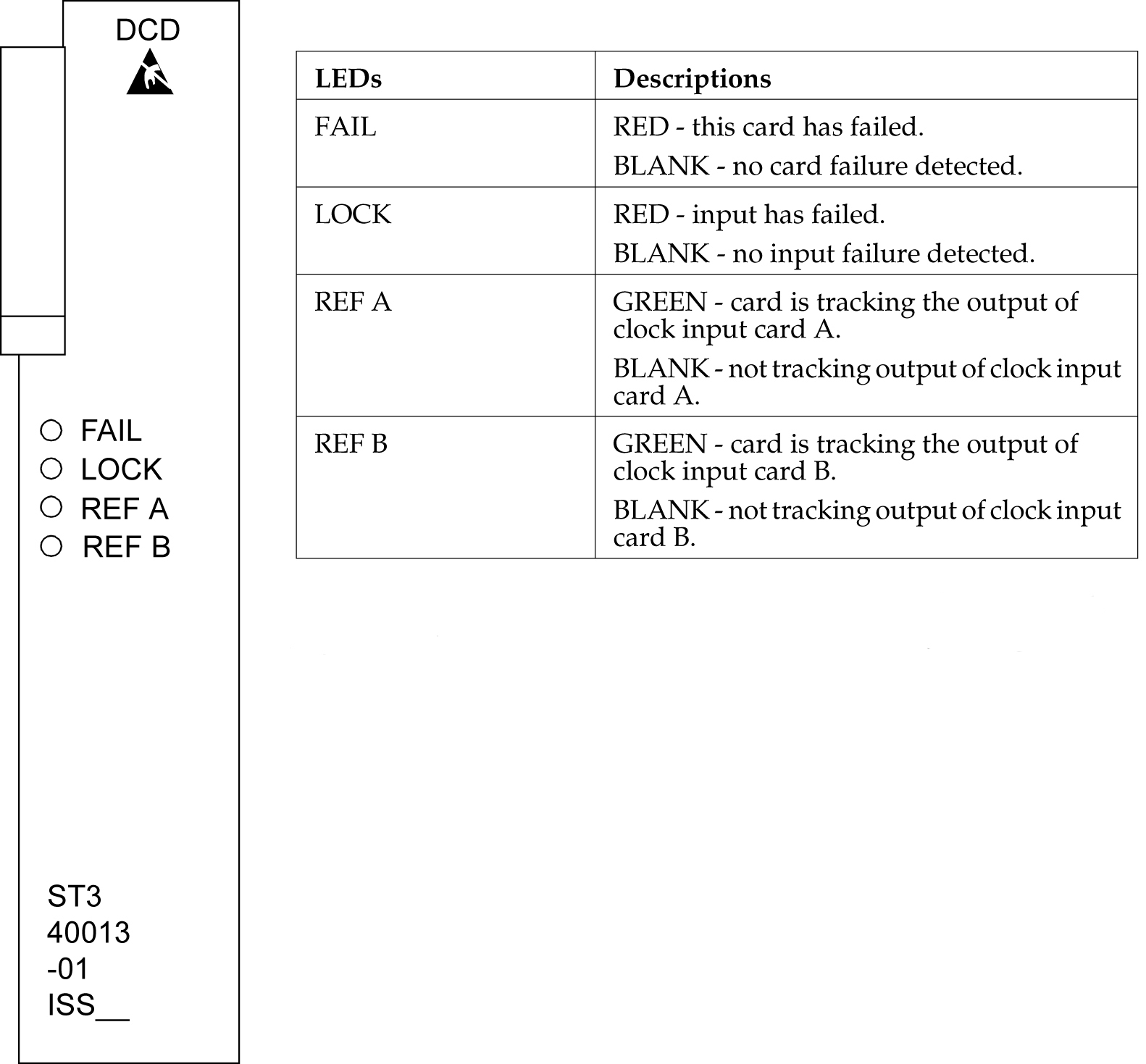

img/t_st3_card_replacement_maintmanual_fig1.jpg

Note:

If the FAIL and LOCKLEDs are both illuminated, the ST3 is in holdover mode and the card has not failed.

A.17.3 MIS Card Replacement

Description

The Maintenance Interface System (MIS) card may be removed or inserted into the shelf at any time without a negative effect to the operation of the shelf. The office alarms and shelf status (except for the battery alarm) do not function while the MIS card is removed from the shelf.

  1. Remove the MIS card from the shelf.
  2. Insert the replacement card.

Figure A-15 Holdover Clock MIS Card LEDs
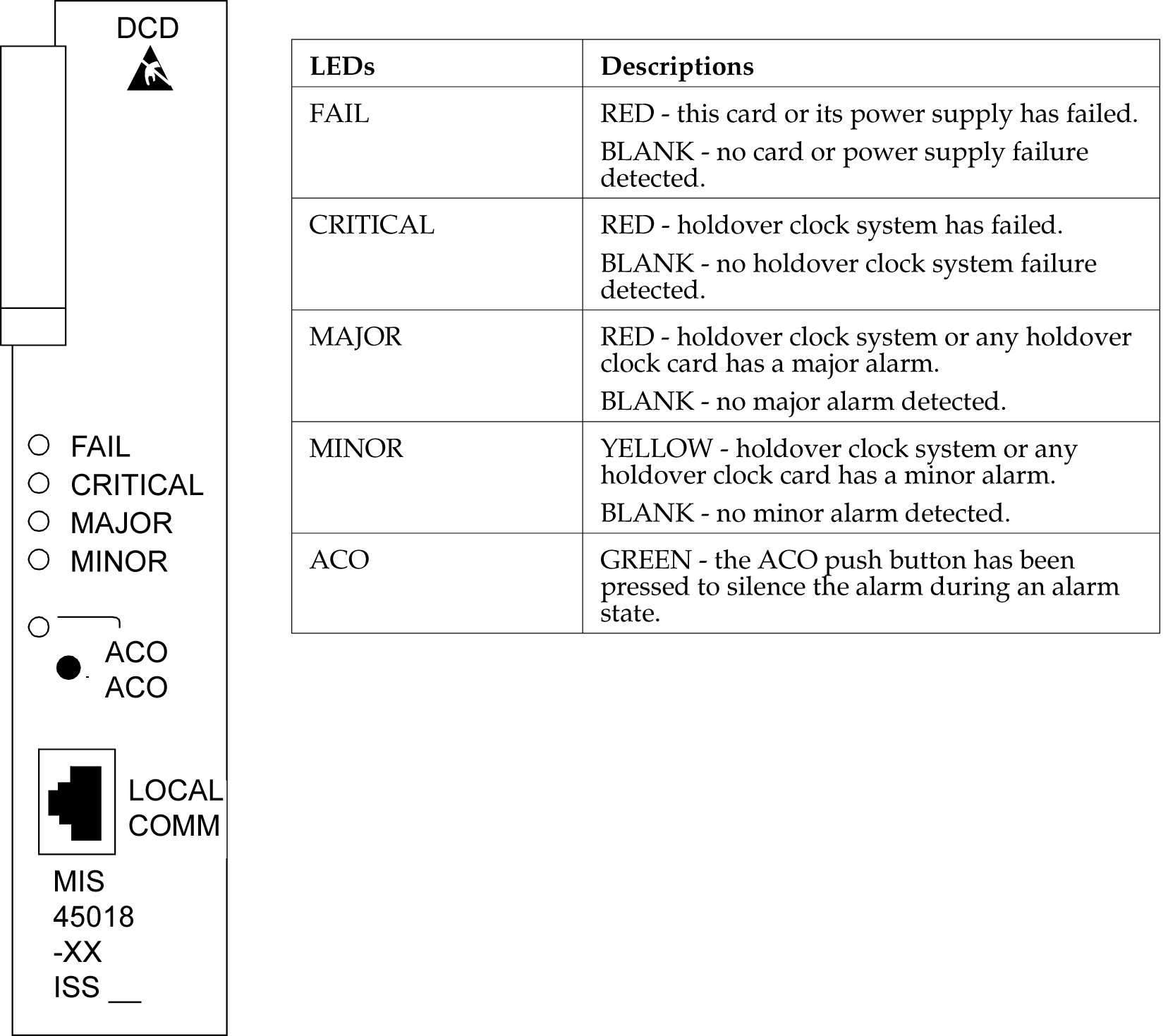

img/t_mis_card_replacement_maintmanual_fig1.jpg

A.17.4 TOCA Card Replacement

When an MCA-5 is installed in the MCA slot, an HS protection switch automatically activates when the TOFAIL or PORTALM lamp is lit. If the TOPORTALM lamp is lit, you must determine whether it is actually a card port failure, or a shorted or unterminated cable external to the shelf. If you determine that the PORTALM is actually a port failure on the card, replace the TO card.

  1. Verify that an HS protection switch has been activated.
    If an automatic protection switch has been activated, the output protection button lamps are lit over the failed card and HSTO card. The MCA-5 AUTO lamp flashes for 6 seconds during the automatic protection switch activation, and then lights steadily.
  2. If an HS protection is not activated, manually activate a switch by simultaneously pressing the output protection buttons over the TO card with FAIL or PORTALM lamp lit and a like HSTO card.
    The output protection button lamps should light over the failed TO card and a like HSTO card, and the MCA-5 MAN lamp flashes until the switch is released.

    Caution:

    The TO cards must not be removed without first activating an HS protection switch to minimize the loss of output signals. The possible output loss times are as follows:
    1. TO card removal: up to 6 seconds
    2. Port or card failure: up to 3 seconds
    3. Manual switch activation/deactivation: approximately one ms.
  3. Remove the TO card from the shelf.
    Set the option switches on the replacement card to the correct settings. Insert the replacement card. The FAIL lamp on the replacement card should remain off and the INPUT lamp should light. The ST lamp should also light if the system is equipped with clock cards.
  4. Wait 10 seconds after all the lamps normalize to allow the card to warm-up and generate outputs.
  5. Press the lit output protection button for the HSTO card slot until the lamp goes out.
    The lamp over the output protection button should go off. This releases the HS protection switch and puts the replacement card online.

Figure A-16 Holdover Clock TOCA Card LEDs
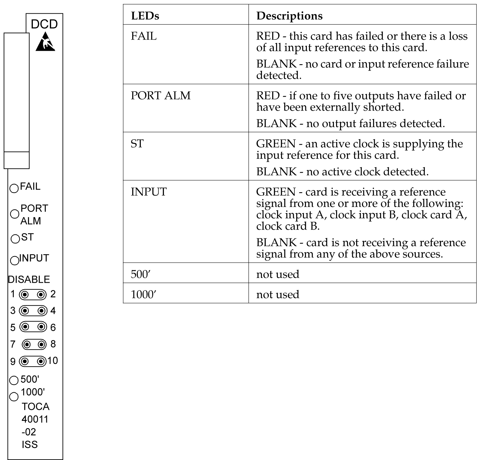

img/t_toca_card_replacement_maintmanual_fig1.jpg

Figure A-17 Holdover Clock MCA Card LEDs
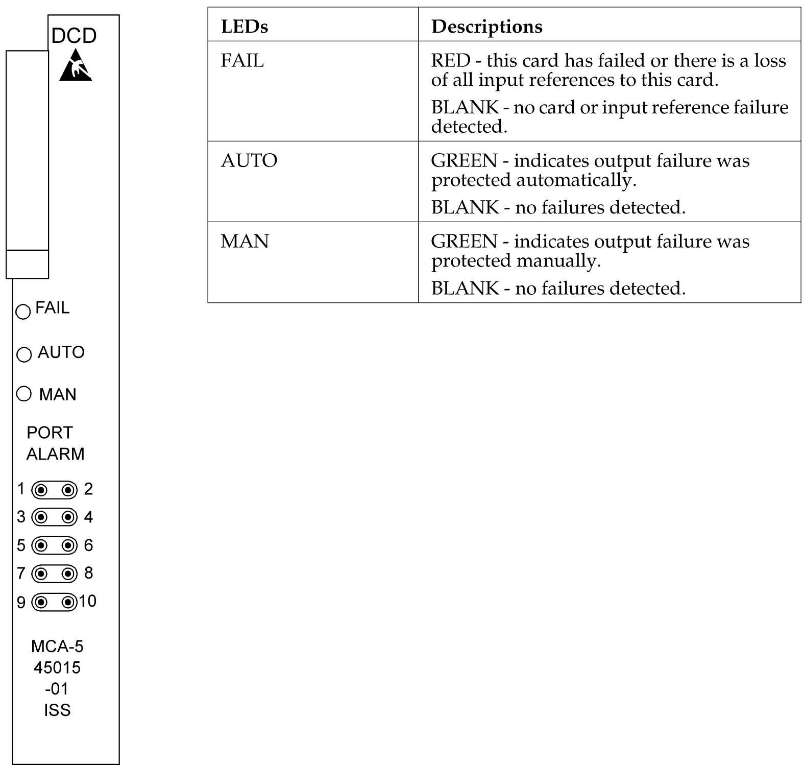

img/t_toca_card_replacement_maintmanual_fig2.jpg

A.18 Fan Assembly P/N 890-0001-xx

The Fan Assembly P/N 890-0001-xx is used for cooling shelves in the EAGLE frame. The assembly includes 3 fan units and a controller card.

Caution:

Do not perform procedures to Replace Fan Assembly if the Fan Assembly is used to cool shelves with HCMIM or HIPR2 cards. contact the My Oracle Support (MOS).

Refer to the following procedures to:

A.18.1 Replace the Fan Unit

Caution:

Be careful when removing fans. Fan blades are exposed along the sides and back of the units. The fan blade speeds of remaining fans will increase after any fan is removed.
  1. Loosen the two captive screws used to secure the fan to be replaced.
    Fan 1 is located next to the Fan controlled card.

    Figure A-18 Fan Unit Mounting Screws


    img/t_fan_assembly_pn_8900001xx_maintmanual_fig1.jpg
  2. Firmly grasp the fan and pull straight out.
    The corresponding LED on the fan controller card is now red.
  3. Insert the replacement fan into the appropriate slot and secure the two captive screws.
    The replaced fan should immediately come up to speed and the speeds of other fans should return to normal. The corresponding LED on the fan controller card is now green.

A.18.2 Replace Fan Controller Card

  1. Remove Fan 1 by removing the two captive screws used to secure Fan 1 (Refer to Replace Fan Assembly).

    Caution:

    Be careful when removing fans. Fan blades are exposed along the sides and back of the units. The fan blade speeds of Fan 2 andFAN 3 will increase after FAN 1 is removed.
    Fan 1 is located next to the Fan card. Firmly grasp Fan 1 and pull straight out.
  2. Remove the fan controller card by removing the two captive screws used to secure the fan controller card.
    Remove Fan Controller Card by pulling straight out.
  3. Insert the replacement fan controller card into the appropriate slot and secure the two captive screws.
  4. Insert Fan 1 back into the space next to the fan controller card and secure (finger tighten) using the two captive screws.
    Fan 1 should immediately come up to speed and the speeds of Fans 2 and 3 should return to normal.

A.18.3 Replace Fan Assembly

Caution:

Do not perform this procedures if the Fan Assembly is used to cool shelves with HCMIM or HIPR2 cards. contact My Oracle Support (MOS).

The following procedures are used to replace Fan Assembly P/N 890-0001-xx when it is used to cool shelves not populated with HCMIM or HIPR2 cards.

A.18.3.1 Procedure - Power Down the Fan Assembly

Use the following procedure to power down the fan assembly.

  1. The fuse card located on the Fuse and Alarm Panel is marked FAN A and FAN B. Fuse positions 6, 12, and 18 are the correct locations on the FAP faceplate. The fans are fused at 3As, with blue flags per feed. Remove the appropriate fuse for the fan assembly being replaced according to the following:
    • Fuse position 6 is for the fan unit directly below the x100 shelf.

    • Fuse position 12 is for the fan directly below the x200 shelf.

    • Fuse position 18 is for the fan directly below the x300 shelf.

  2. When both the A side and B side power is removed from the fan unit, all of the LEDs on the fan controller card (located on the left side of the front of the fan unit) are no longer illuminated and the all fan motors are off.

    Figure A-19 Fan card with LEDs on front of fan assembly unit


    img/t_replace_hcmim_fan_asembly_maintmanual_fig1.jpg

A.18.3.2 Procedure - Remove Fan Cables and Fan Assembly

Use the following procedure to remove fan cables and fan assembly.

  1. At the fan assembly, place fiber paper on the shelf below where the fan is to be replaced. This ensures that nothing drops into the area or equipment below.
  2. From the front of the frame remove the fan filter from the fan assembly.
  3. From the rear of the fan unit, loosen the screws on the fan unit connector marked FAN A POWER. Remove the connector from the fan unit.
  4. From the rear of the fan unit, loosen the screws on the fan unit connector marked FAN B POWER. Remove the connector from the fan unit.
  5. Remove the screws from the the left and right sides of the rear of the fan tray bracket. There are two screws on each side. These screws must be removed from the rear of the frame.

    Figure A-20 Fan Assembly Rear Bracket Screws.


    img/t_replace_hcmim_fan_asembly_maintmanual_fig2.jpg

  6. With the screws removed, carefully push on the rear of the unit until the fan assembly moves forward about an inch.
  7. From the front of the frame remove the fan assembly from the the fan bracket. For easier removal, tilt the unit as it is removed.
A.18.3.3 Procedure - Install the Fan Assembly

Use the following procedure to install the fan assembly.

  1. Remove the new fan unit from the container. The fan unit is shipped with the three fans already installed.

    Figure A-21 Fan Assembly


    img/t_replace_hcmim_fan_asembly_maintmanual_fig3.jpg

  2. Insert the fan unit into the fan bracket. Tilt the unit up as it is pushed in and completely inserted into the bracket. After insertion, be sure the front of the fan unit is recessed about 1/2 inch from the front frame rails to allow the door to close.

    Figure A-22 Fan tray inserted into fan tray bracket in the frame - front view


    img/t_replace_hcmim_fan_asembly_maintmanual_fig4.jpg

  3. When the fan unit is aligned and in place, attach the fan unit to the fan tray bracket by tightening the screws on the left and right sides of the rear of the fan tray bracket. There are two screws on each side. These screws must be tightened from the rear of the frame.

    Figure A-23 Tighten rear fan tray screws


    img/t_replace_hcmim_fan_asembly_maintmanual_fig5.jpg

  4. From the front of the frame install the fan filter into the fan assembly.
  5. At this time check and tighten all screws, including the screws holding the side brackets to the frame (if necessary). The side bracket screws should be tightened fully from the rear of the frame. Use a long hex driver or flat head screw driver.

    Figure A-24 Tighten fan side bracket screws


    img/t_replace_hcmim_fan_asembly_maintmanual_fig6.jpg

  6. Connect the fan cable at the rear of the fan assembly on the J9 connector to the FAN A POWER.
  7. Connect the fan cable at the rear of the fan assembly on the J8 connector to the FAN B POWER.
  8. Remove the piece of fiber paper on the top of the shelf below where the fan assembly was installed. This procedure is complete.

    Caution:

    Before powering up the fans, ensure that the shelf directly above the fan does not contain any empty slots. Install an air management card in any empty slots to ensure proper air flow. These filler cards have no electrical connection to the system. See Replacing a Card in the EAGLE for general card installation guidelines.
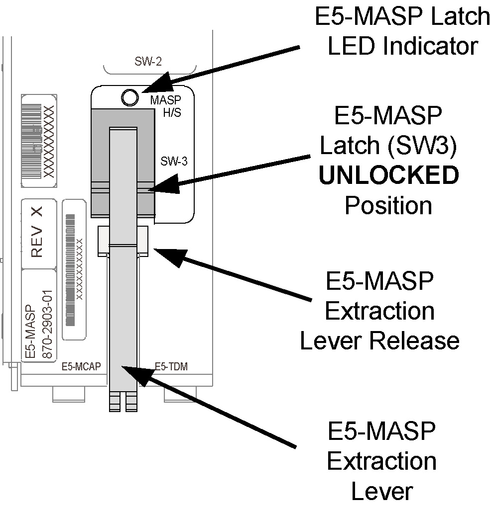
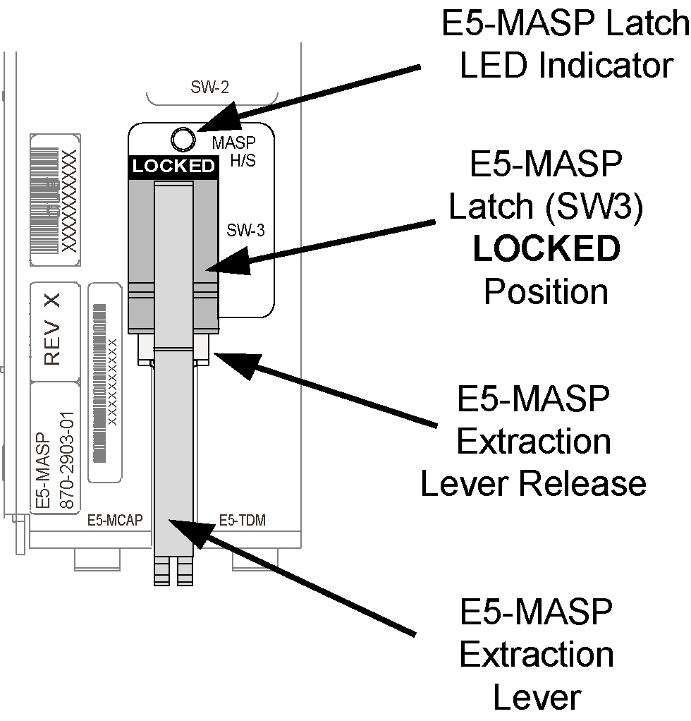
A.18.3.4 Procedure - Power Up the Fan Assembly

Use the following procdure to power up the fan assembly.

All fans are fused at 3A (blue) per feed.

Caution:

Before powering up the fans, ensure that the shelf directly above the fan does not contain any empty slots. Install an air management card in any empty slots to ensure proper air flow. These filler cards have no electrical connection to the system. See Replacing a Card in the EAGLE for general card installation guidelines.
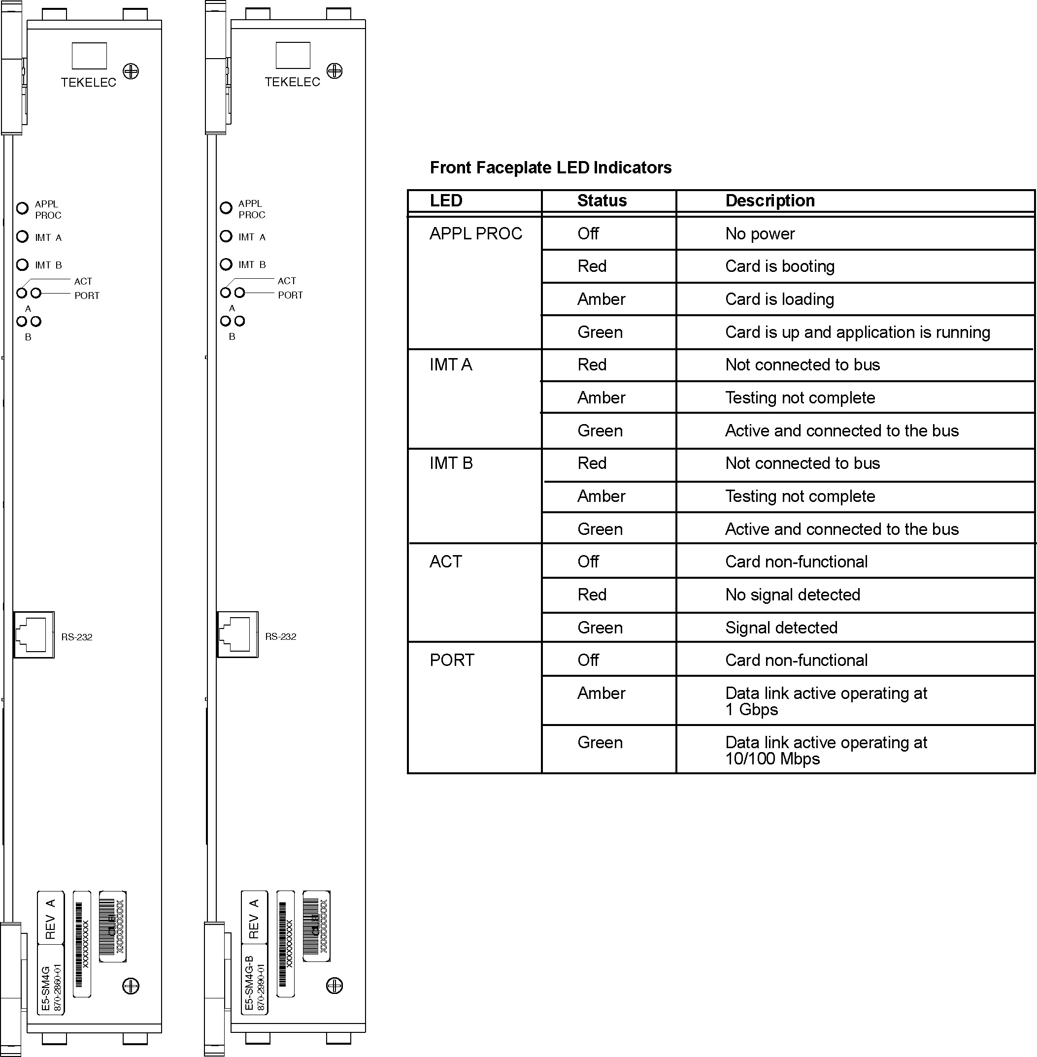
  1. After the fan is installed, the powering up process depends on the shelf location.
    1. The fuse cards located on the Fuse and Alarm Panel are marked FAN A and FAN B, fuse positions 6, 12, and 18 are marked correct locations on the FAP faceplate.
    2. Fuse position 6 is for the fan unit directly below the x100 shelf.
    3. Fuse position 12 is for the fan directly below the x200 shelf.
    4. Fuse position 18 is for the fan directly below the x300 shelf.
    5. All fans are to be fused at 3As, with blue flags, per feed.
    6. Fill out the fuse card completely.
    7. Ensure the FAP fuse location for the fan is properly labeled.
  2. Fifteen seconds after both the A side and B side power is connected to the fan assembly all of the LEDs on the fan controller card (located on the left side of the front of the fan assembly) are green.

    Figure A-25 Fan card with LEDs on front of fan assembly


    img/t_replace_hcmim_fan_asembly_maintmanual_fig7.jpg

  3. When the fans are powered up and running, a test must be conducted to ensure proper service.
    Go to the system terminal.
  4. Check to see if the fan feature is activated.
    At the terminal, enter the command:
    rtrv-feat
    Example output:
    
     rlghncxa03w 04-01-28 11:34:04 EST  EAGLE 34.0.0.
        EAGLE FEATURE LIST
        GTT      = on      GWS      = off     NRT      = off
        X25G     = off     LAN      = off     CRMD     = off
        SEAS     = off     LFS      = off     MTPRS    = off
        FAN      = off     DSTN5000 = off     WNP      = off
        CNCF     = off     TLNP     = off     SCCPCNV  = off
        TCAPCNV  = off     IPISUP   = off     DYNRTK   = off
        X252000  = off     INP      = off     PLNP     = off
        NCR      = off     ITUMTPRS = off     SLSOCB   = off
        EGTT     = off     VGTT     = off     MGTT     = off
        MPC      = off     ITUDUPPC = off     GFLEX    = off
        GPORT    = off     MEASPLAT = off     TSCSYNC  = off
        E5IS     = off
    ;
    
    If the fan feature is off (illustrated in the example), go to 5. Otherwise, go to 6.
  5. At the terminal, enter the command:chg-feat:fan=on
    With this command the user will perform the tests beginning with 7.
  6. At the terminal, enter the command: rept-stat-trbl
    Check to see that there are no fan errors. Specifically, check that there are no “#302 Cooling Fan Failure” errors. Next, perform the tests beginning with 7.
  7. Fan Verification (perform 7 through 12 for each fan assembly).
    Move to the rear of the frame and remove the A POWER cable from the FAN unit. Result: Fan 2 and Fan 3 LEDs will blink as the fans speed up to maximum speed. This may take up to 15 seconds. Once maximum speed has been reached Fan 2 and Fan 3 LEDs on the Fan Controller card will be solid green. Fan 1 LED should be red. The controller LED should be blinking green. Fan 1 should stop running and the MINORLED should be lit.
  8. At the system terminal enter the command:rept-stat-trbl
    Test each fan to ensure that the alarm and the units are working correctly. The terminal reports:
    
    # 302 Cooling Fan Failure
    
  9. Replace the A POWER cable on the back of the FAN unit and secure the connector.
    Result: All fans are running and the MINORLED is not lit. The terminal reports:
    
    # 303 Cooling Fans Normal
    
  10. Remove the B POWER cable from the FAN unit.
    Result: Fan 1 and Fan 2 LEDs will blink as the fans speed up to maximum speed. This may take up to 15 seconds. Once maximum speed has been reached Fan 1 and Fan 2 LEDs will be solid green. Fan 3 LEDshould be red. The fan controller LED should be blinking. Fan 3 should stop running and the MINORLEDshould be lit.
  11. At the system terminal enter the command: rept-stat-trbl
    Test each fan to ensure that the alarm and the units are working correctly. The terminal reports:
    
    # 302 Cooling Fan Failure
    
  12. Replace the B POWER cable on the back of the FAN unit and secure the connector.
    Result: The fans are running and the MINORLED is not lit. The terminal reports:
    
    # 303 Cooling Fans Normal
    
  13. Repeat 7 through 12 for each fan unit installed.
    This procedure is complete.