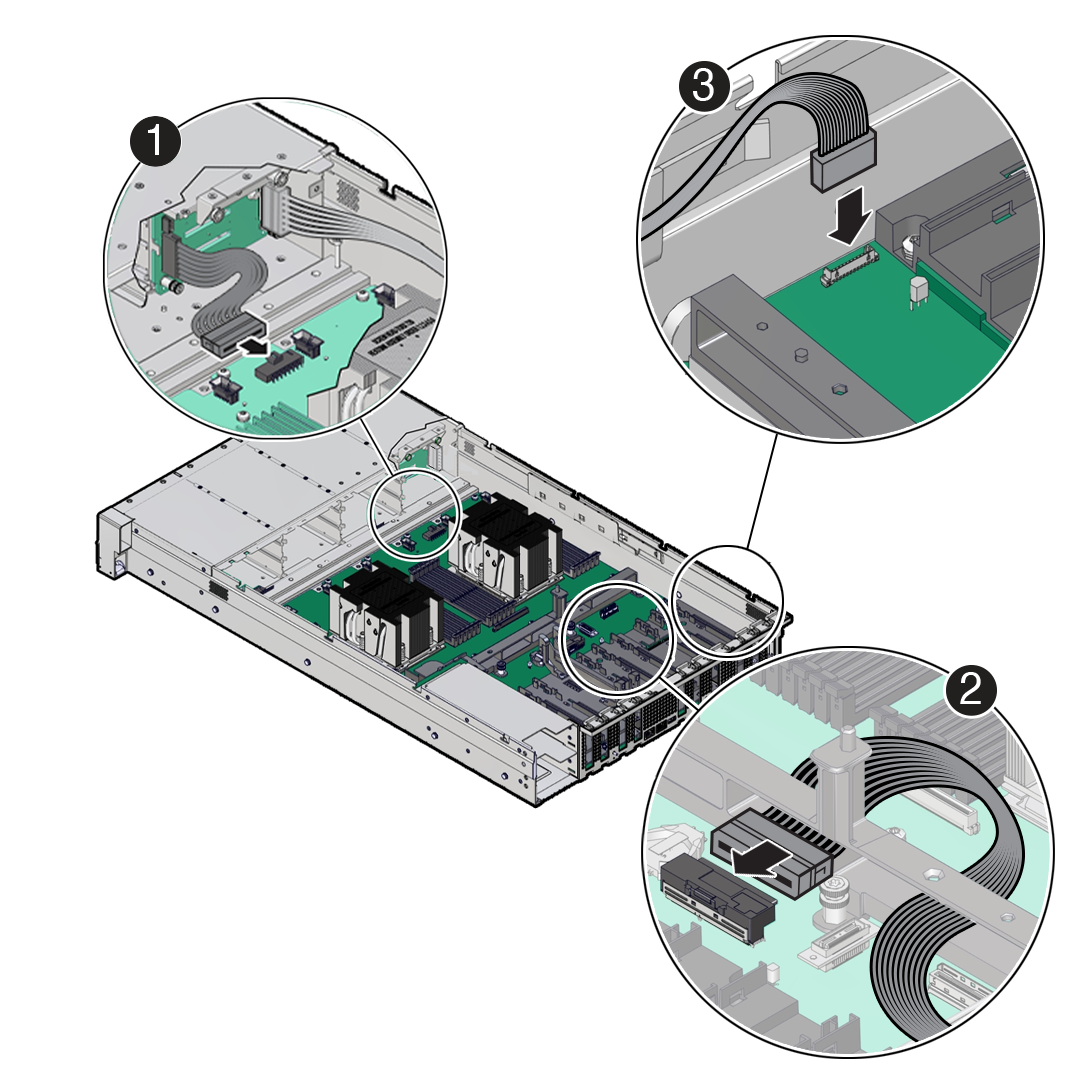
5 Servicing FRUs
Perform tasks for servicing field-replaceable units (FRUs) for the Oracle Database Appliance that require you to power off the system and/or server node.
When servicing FRU components, the server node and/or system must be powered down and the AC power cords disconnected.
Note:
Only authorized Oracle Service personnel can service FRU components.
- Servicing Processors (FRU)
Perform tasks described in this section to service processors. - Servicing the Fan Tray (FRU)
Perform tasks in this section to service the fan tray. - Servicing the Disk Backplane (FRU)
Perform tasks in this section to service the disk backplane. - Servicing the Front LED Indicator Module (FRU)
Perform tasks in this section to service the front LED indicator module. - Servicing the PCIe Slot Flyover Cable (FRU)
Perform tasks in this section to service the PCIe Slot Flyover Cable. - Servicing the Motherboard Assembly (FRU)
This section describes how to service the motherboard assembly. - Component Fault Management
Perform component fault management on Oracle Database Appliance systems.
Servicing Processors (FRU)
Perform tasks described in this section to service processors.
Processors are replaceable components that require you to power off the server before servicing.
Caution:
Ensure that all power is removed from the server before removing or installing a processor. You must disconnect the power cables from the system before performing these procedures.Caution:
These procedures require that you handle components that are sensitive to electrostatic discharge. This sensitivity can cause the component to fail. To avoid damage, ensure that you follow electrostatic discharge safety measures and antistatic practices. See Electrostatic Discharge Safety.Note:
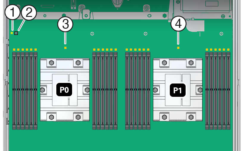
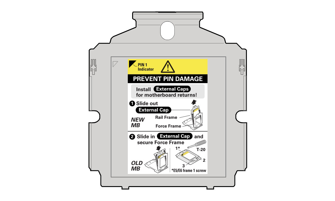
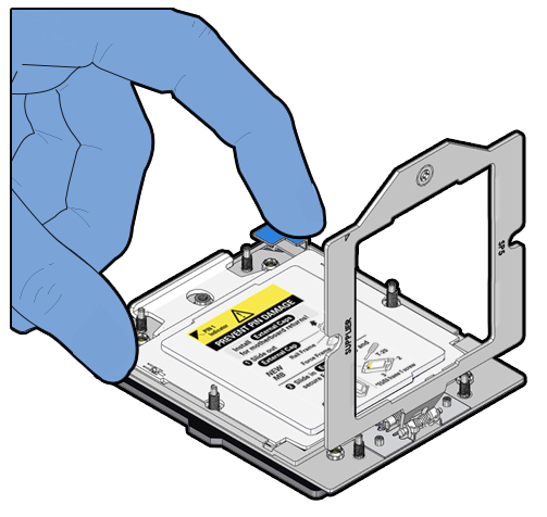
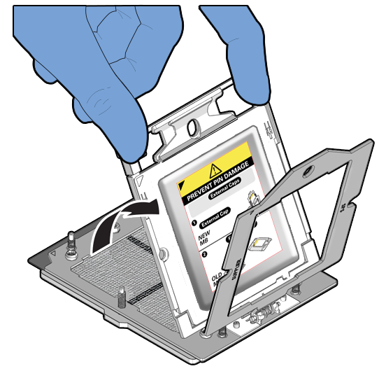
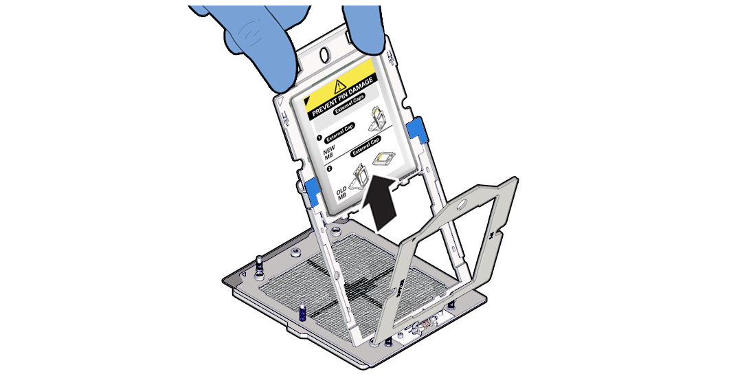
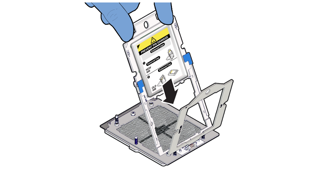
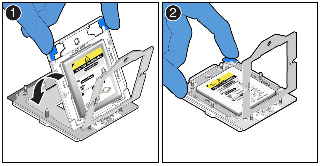
On single-processor systems, processor socket 1 (P1) is shipped without a heatsink and with an External Cap. To protect the delicate processor socket pins, do not remove the External Cap that was installed on the motherboard.Processor Overview
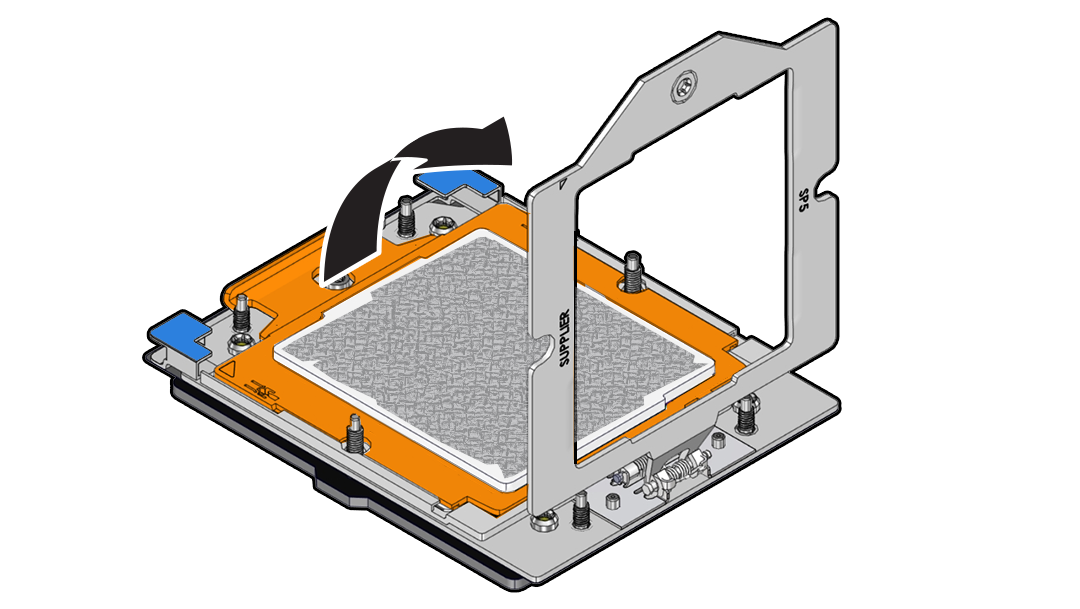
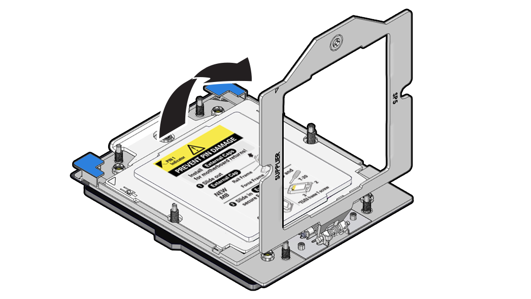
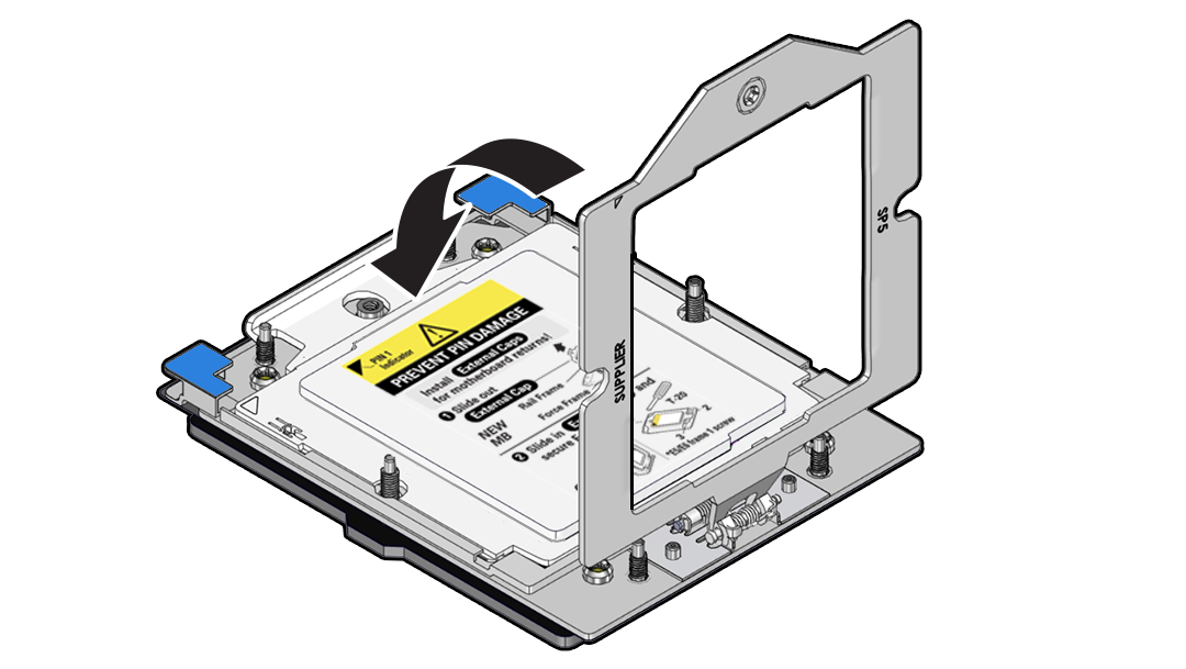
Socket components in the processor assembly have a pin 1 indicator to aid in assembly.
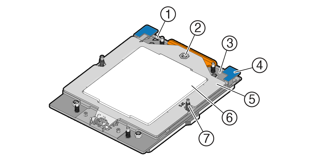
Description of the illustration mm-11076_processor-components.png
| Callout | Description |
|---|---|
|
1 |
Pin 1 orientation |
|
2 |
Force Frame Retention Screw (captive) |
|
3 |
Rail Frame (socket stiffener frame) |
|
4 |
Release Tabs (2x) |
|
5 |
Force Frame (retention frame) |
|
6 |
Processor Package (carrier frame holding preinstalled processor) |
|
7 |
Heatsink Attachment Studs (6x) |
Parent topic: Servicing Processors (FRU)
Identify and Remove a Processor
-
Use ESD gloves (not latex or vinyl), if possible, when handling the processor.
-
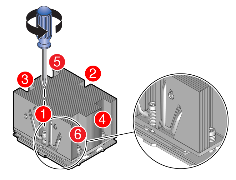
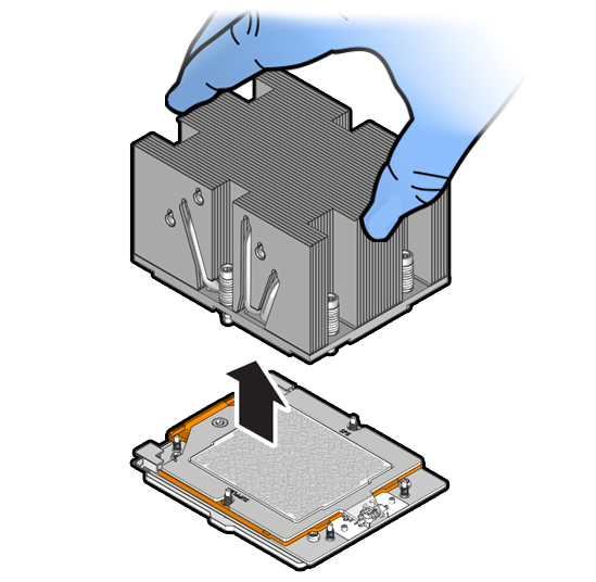
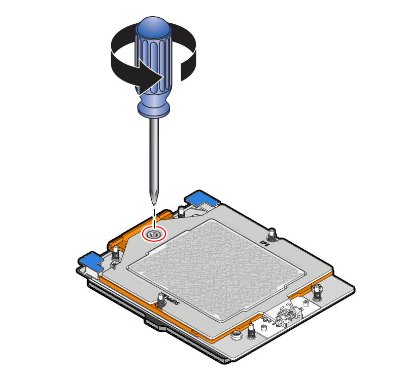
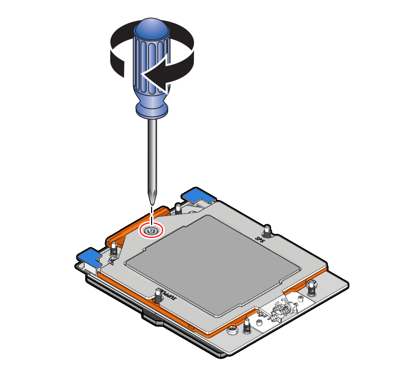
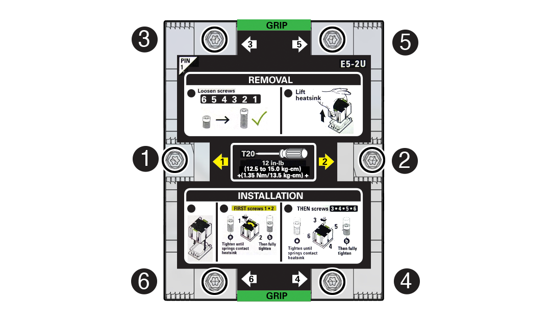
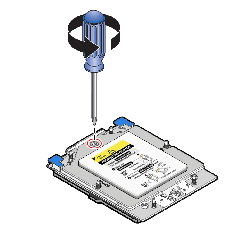
Obtain a Torx T20 screwdriver for processor and heatsink removal.
-
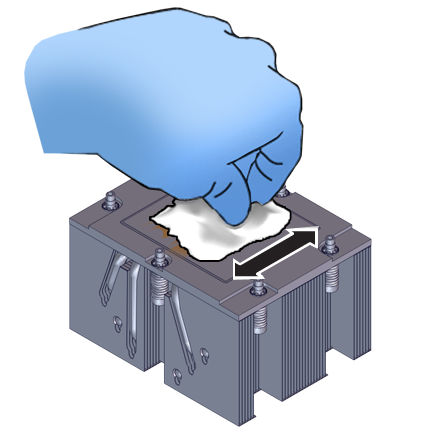
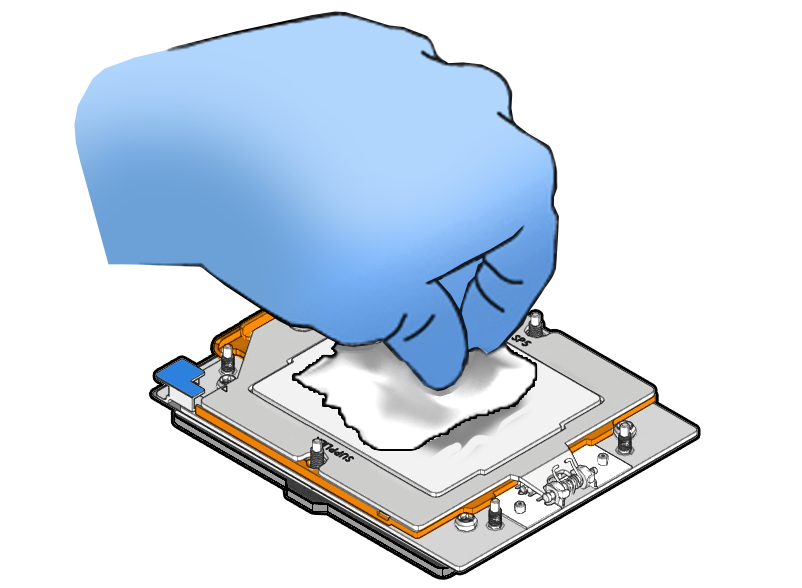
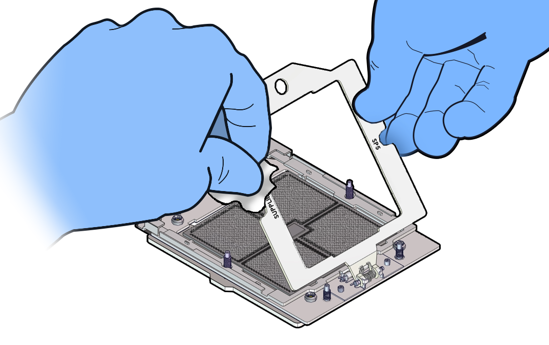
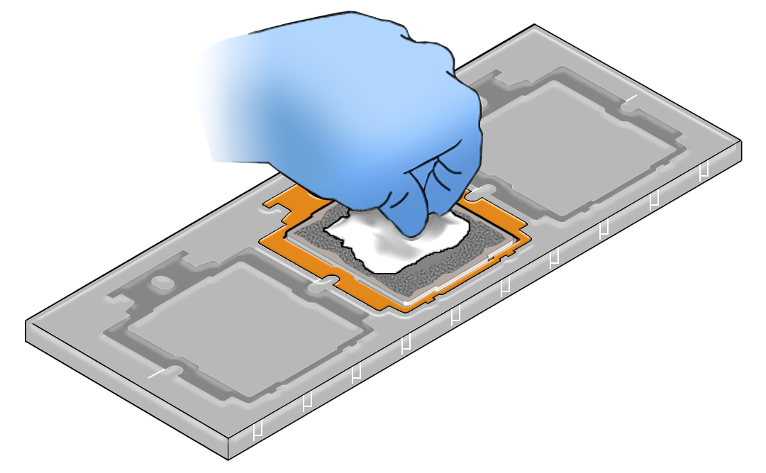
Obtain the materials required to remove the old thermal interface material (TIM).
- Isopropyl alcohol wipes (included with FRU kit)
- Techwipes or similar low-lint and low-abrasion wipe
- Isopropyl alcohol (90% or above recommended)
Caution:
Failure to remove/replace the old TIM can result in processor overheating.
-
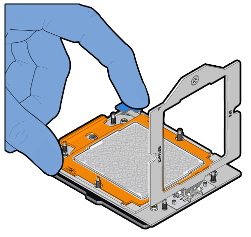
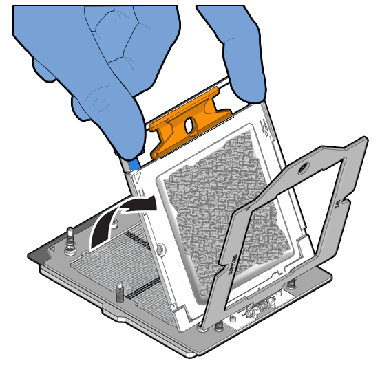
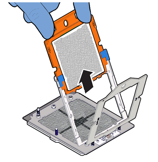
Be careful not to touch the processor socket pins.
Caution:
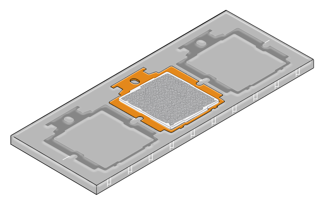
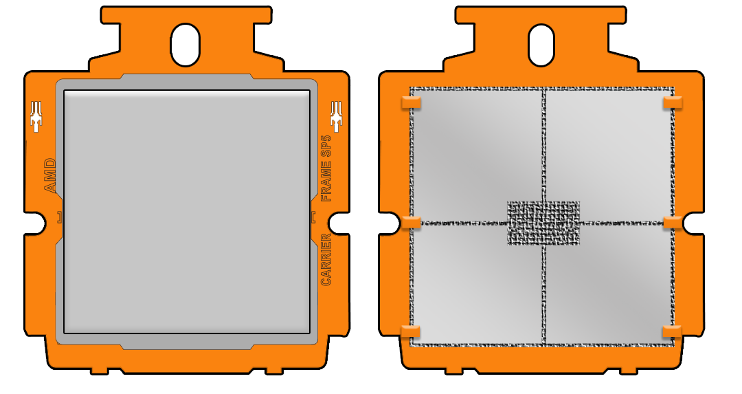
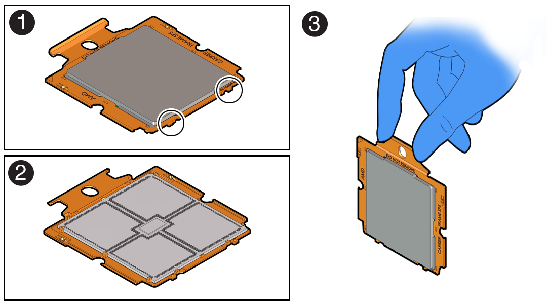
The processor socket pins are very fragile. A light touch can bend the processor socket pins beyond repair. - Replacement processors come preinstalled on a special carrier to ensure
safe handling. Never remove the processor from its carrier.
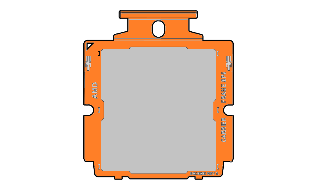
Description of the illustration mm-10729_processor-carrier_2.png -
On a two processor system, if you remove a processor for replacement do not attempt to operate the system with a single processor as the server might overheat due to improper airflow. A two processor system requires both processors and their heatsinks installed to operate properly.
Parent topic: Servicing Processors (FRU)
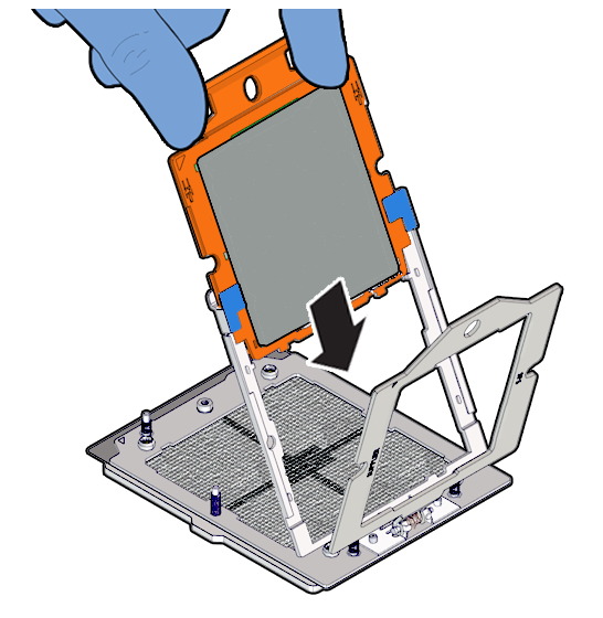
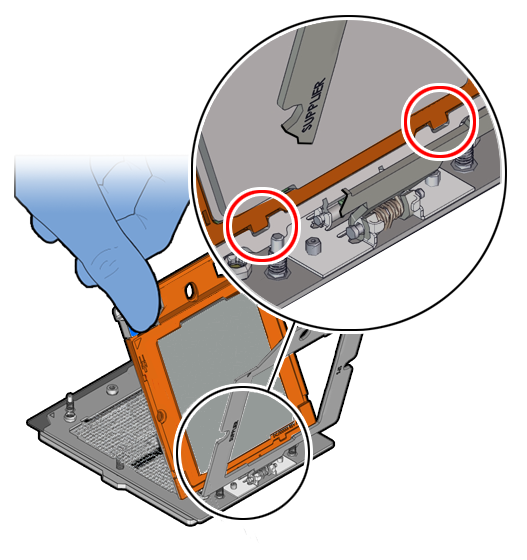
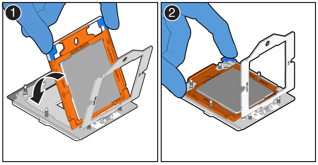
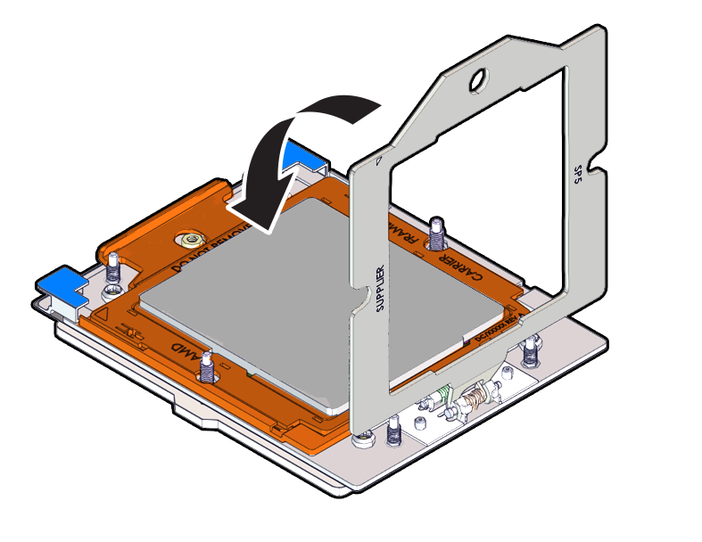
Install a Processor
-
Use ESD gloves (not latex or vinyl), if possible, when handling the processor.
-
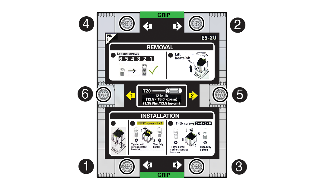
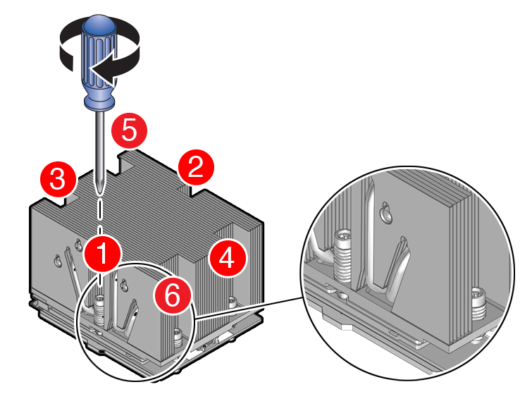
Obtain a torque driver set to 12 in-lb (inch-pound or 1.35 Nm/13.5 kg-cm) force with a T20 Torx bit for processor and heatsink installation.
-
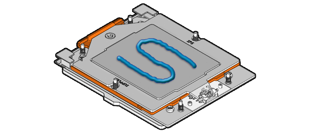
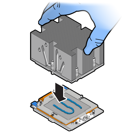
All of the old thermal interface material (TIM) should have been removed. Failure to remove/replace the old TIM can result in processor overheating.
-
Be careful not to touch the processor socket pins.
Caution:
The processor socket pins are very fragile. A light touch can bend the processor socket pins beyond repair. -
If you are replacing a processor, ensure that the replacement processor is identical to the processor that was removed. A list of supported processors can be found in the Owner's Guide.
Parent topic: Servicing Processors (FRU)
Servicing the Fan Tray (FRU)
Perform tasks in this section to service the fan tray.
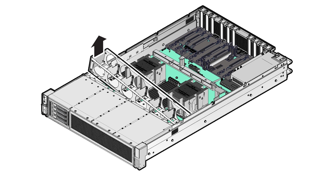
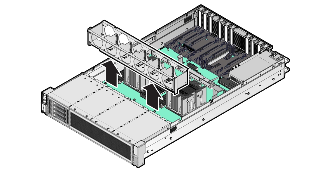
The fan tray might need to be removed when servicing the disk backplane and motherboard assembly. Removing the fan tray requires you to power off the server.
Caution:
Ensure that all power is removed from the server before removing or installing the disk backplane. You must disconnect the power cables before performing this procedure.Caution:
These procedures require that you handle components that are sensitive to electrostatic discharge. This sensitivity can cause the component to fail. To avoid damage, ensure that you follow electrostatic discharge safety measures and antistatic practices. See Electrostatic Discharge Safety.Parent topic: Servicing FRUs
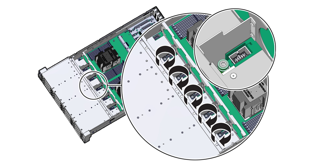
Remove the Fan Tray
Perform this procedure only when servicing disk backplane and motherboard assembly replaceable components.
Parent topic: Servicing the Fan Tray (FRU)
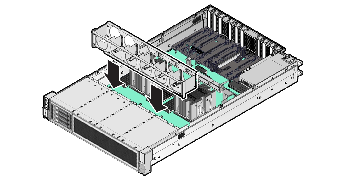
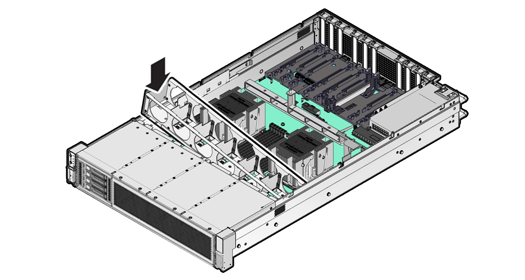
Install the Fan Tray
Perform this procedure only when servicing disk backplane and motherboard assembly replaceable components.
Parent topic: Servicing the Fan Tray (FRU)
Servicing the Disk Backplane (FRU)
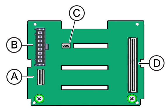
Perform tasks in this section to service the disk backplane.
The disk backplane (DBP) is a replaceable component that requires you to power off the server before servicing.
Caution:
Ensure that all power is removed from the server before removing or installing the disk backplane. You must disconnect the power cables before performing this procedure.Caution:
These procedures require that you handle components that are sensitive to electrostatic discharge. This sensitivity can cause the component to fail. To avoid damage, ensure that you follow electrostatic discharge safety measures and antistatic practices. See Electrostatic Discharge Safety.- Remove the 4-Drive Backplane
- Install the 4-Drive Backplane
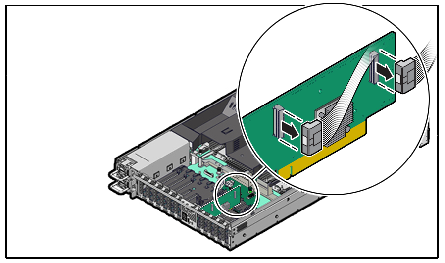
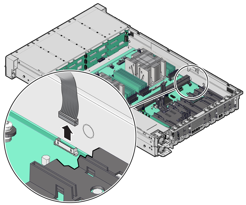
- Remove a Disk Backplane Cable
- Install a Disk Backplane Cable
Parent topic: Servicing FRUs
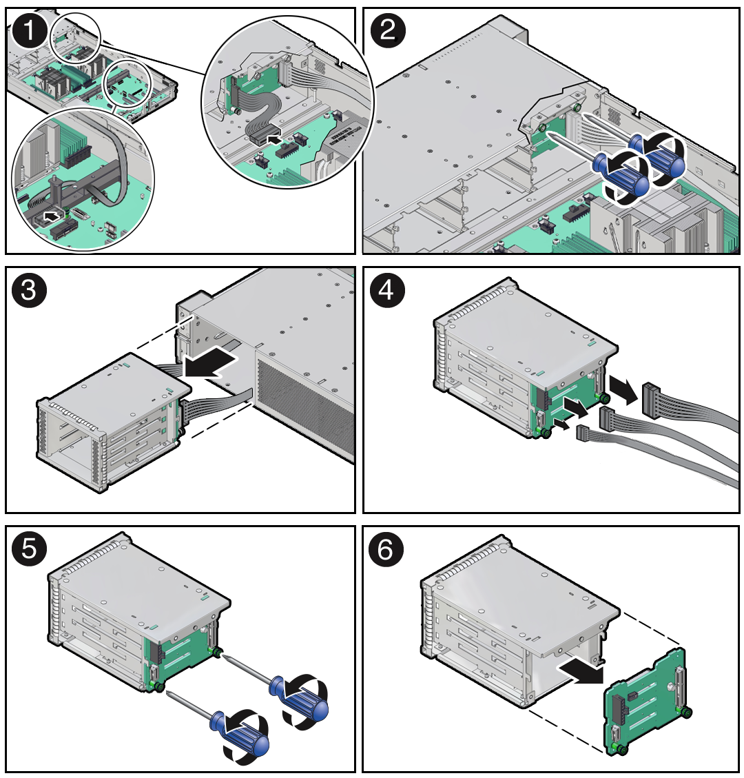
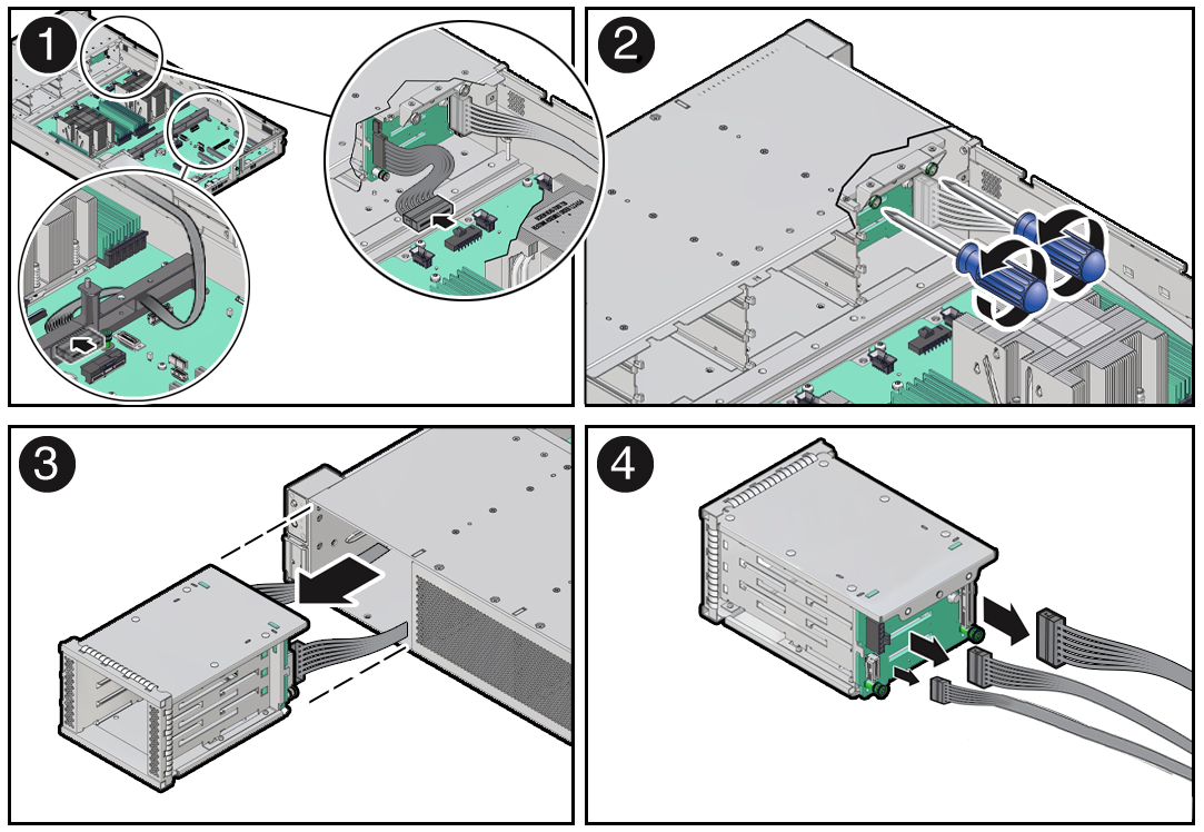
Remove the 4-Drive Backplane
To remove the storage drive cage and 4-Drive disk backplane:
Parent topic: Servicing the Disk Backplane (FRU)
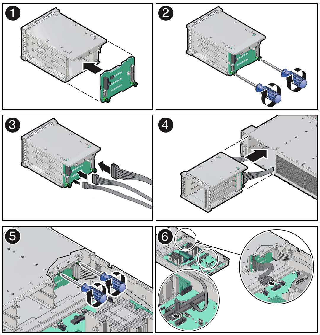
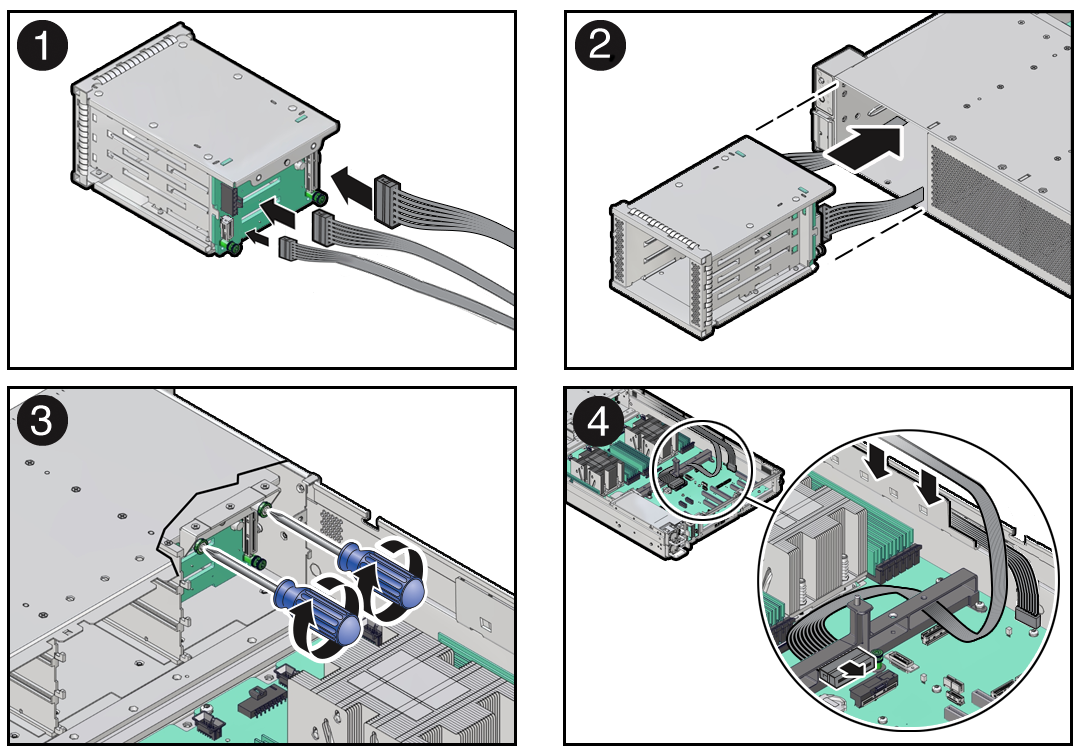
Install the 4-Drive Backplane
To install the 4-Drive disk backplane and storage drive cage:
Parent topic: Servicing the Disk Backplane (FRU)
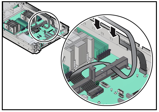
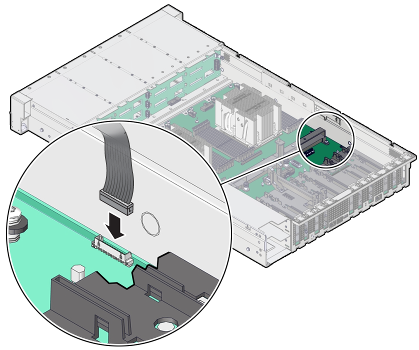
Install a Disk Backplane Cable
- Unpack the replacement disk backplane cable and place it on an antistatic mat.
- Connect the replacement cable the disk backplane and reinstall the storage drive
cage in to the chassis.
- Return the server to operation.
Parent topic: Servicing the Disk Backplane (FRU)
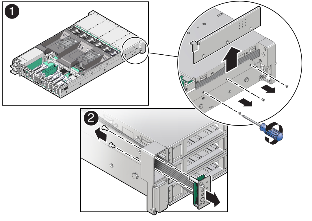
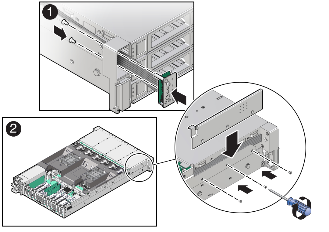
Servicing the Front LED Indicator Module (FRU)
Perform tasks in this section to service the front LED indicator module.
The front LED indicator module is a replaceable component that requires you to power off the server before servicing.
Caution:
Ensure that all power is removed from the server before removing or installing a front LED indicator module. You must disconnect the power cables before performing this procedure.Caution:
These procedures require that you handle components that are sensitive to electrostatic discharge. This sensitivity can cause the component to fail. To avoid damage, ensure that you follow electrostatic discharge safety measures and antistatic practices. See Electrostatic Discharge Safety.Parent topic: Servicing FRUs
Servicing the PCIe Slot Flyover Cable (FRU)
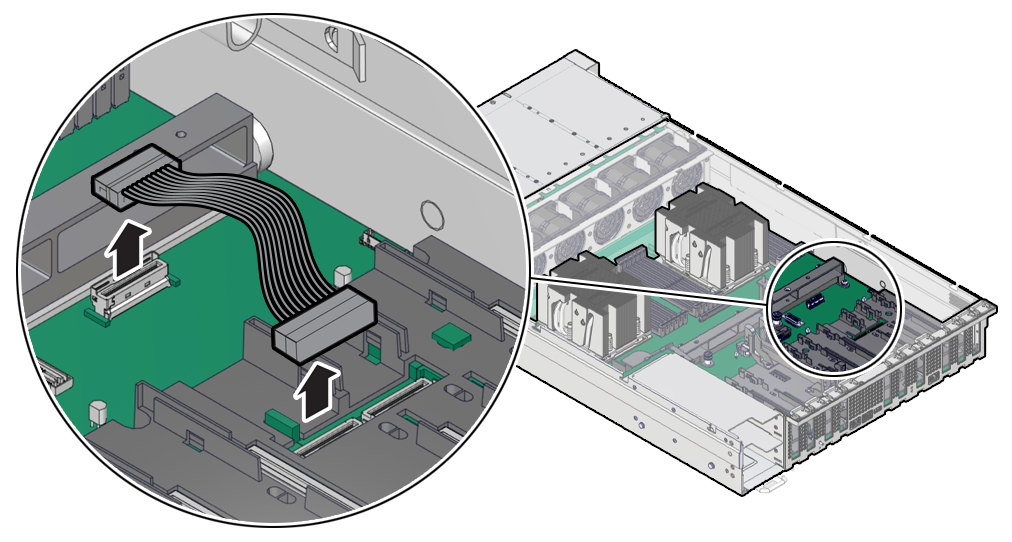
Perform tasks in this section to service the PCIe Slot Flyover Cable.
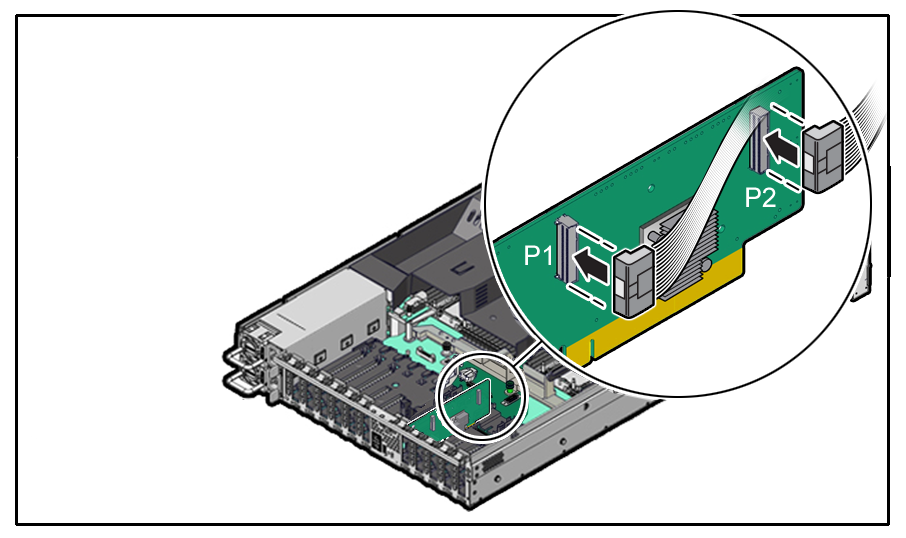
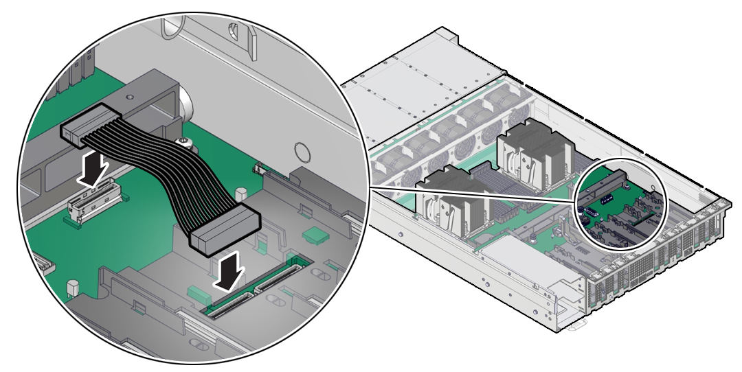
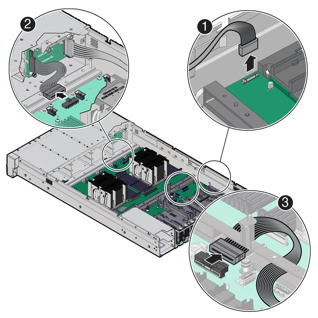
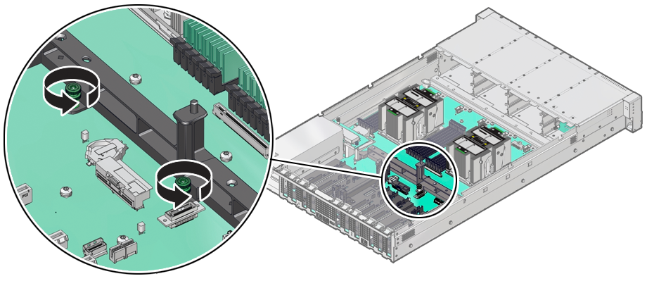
Remove the PCIe Flyover Cable
Note:
The use of PCIe slot 7 is not supported for this product.Parent topic: Servicing the PCIe Slot Flyover Cable (FRU)
Servicing the Motherboard Assembly (FRU)
This section describes how to service the motherboard assembly.
The motherboard assembly is a replaceable component that requires you to power off the server before servicing.
Caution:
Ensure that all power is removed from the server before removing or installing the motherboard. You must disconnect the power cables before performing these procedures.Caution:
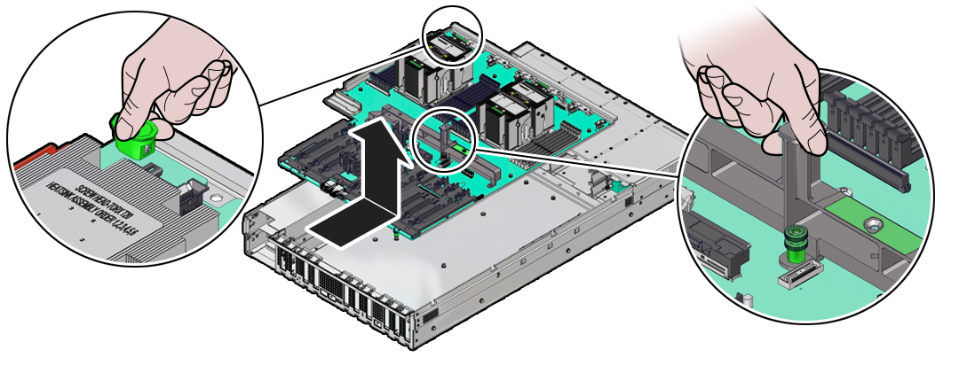
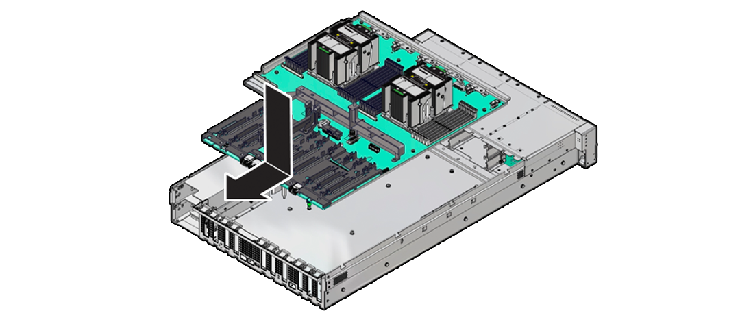
These procedures require that you handle components that are sensitive to electrostatic discharge. This sensitivity can cause the component to fail. To avoid damage, ensure that you follow electrostatic discharge safety measures and antistatic practices. See Electrostatic Discharge Safety.Remove the Motherboard Assembly
-
Use ESD gloves (not latex or vinyl), if possible, when handling components.
-
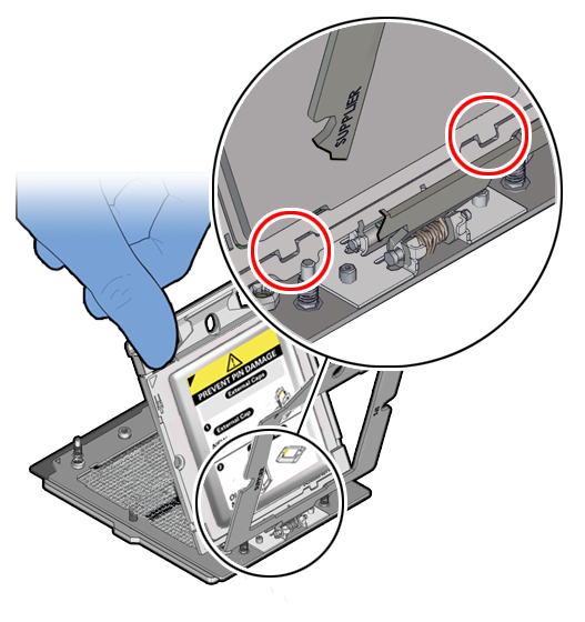
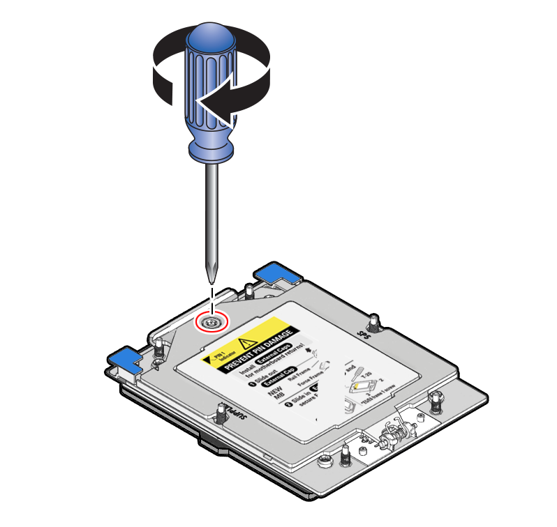
Obtain a Torx T20 screwdriver for processor socket external cap removal.
-
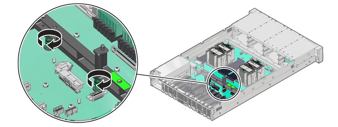
Obtain a Torx T25 screwdriver for motherboard removal.
-
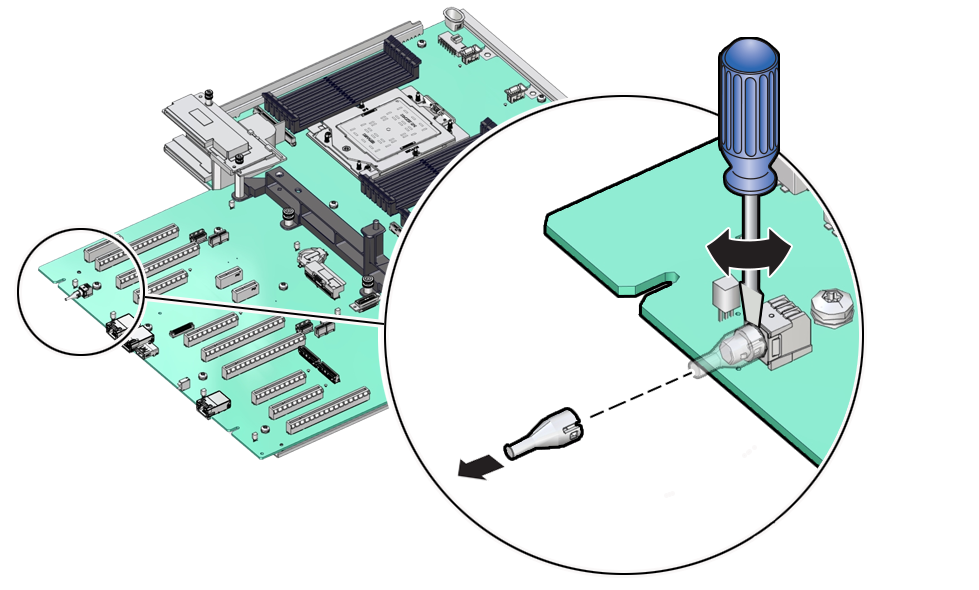
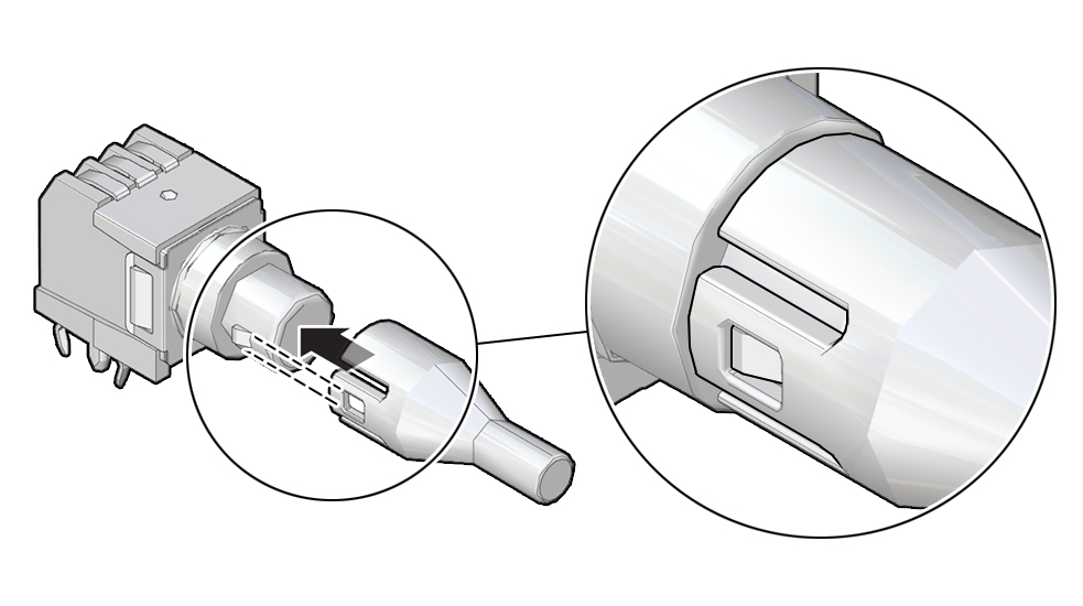
Obtain a small flat blade screwdriver for light pipe removal from the old motherboard.
Caution:
Use the Oracle ILOM backup utility prior to removing the motherboard. This utility backs up the Oracle ILOM configuration of the service processor. Refer to Oracle ILOM Documentation.Parent topic: Servicing the Motherboard Assembly (FRU)
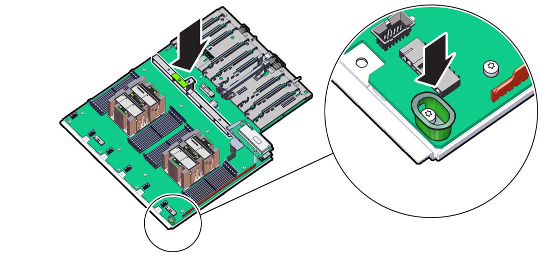
Install the Motherboard Assembly
-
Use ESD gloves (not latex or vinyl), if possible, when handling components.
-
Obtain a Torx T25 screwdriver for motherboard installation.
Parent topic: Servicing the Motherboard Assembly (FRU)
Component Fault Management
Perform component fault management on Oracle Database Appliance systems.
Typically, when a faulty component is replaced and the server is returned to service, the fault state of the component in Oracle ILOM is automatically cleared and the component Service Required indicator will turn off. This is the default behavior for all components that have an embedded FRU serial number in the component firmware.
For replaced components that do not have an embedded FRU serial number, or do not automatically clear their fault state after the component has been repaired and the server is returned to service, you can use Oracle ILOM command line interface to manually clear the fault state. Use the following syntax:
set /path_to_target clear_fault_action=true
Where path_to_target is the path to the component (such as a DIMM) that had the fault.
In addition, the Fault Management shell can also be used. Use of the Fault Management shell is reserved for Oracle Service. For more information on component fault management:
Refer to the Oracle ILOM User's Guide for SystemMonitoring and Diagnostics available in the Oracle ILOM Documentation Library for your version of Oracle ILOM.
Parent topic: Servicing FRUs
