Creating an Enterprise Process
You can create an enterprise process using the design mode in the Enterprise Modeler. The design mode enables you to select a template provided by the system and configure the source of data for metrics, measurements, and KPIs, and to define certain aggregations or calculations (sum, average, and so on.) for those metrics. You can then save your configurations as a process UDO. For more information, see User Defined Object (UDO) Features in Enterprise Process Manager.
To create a new enterprise process:
-
Access the JD Edwards EnterpriseOne application.
-
From the User menu, click Manage Content, and select Processes.
The system displays the Create Process window.
Note:The Create Process window is only displayed when you are creating an enterprise process for the first time. After creating a process, when you click Processes again, the system displays the previously created process layout along with the template used for its creation and the design time options.
If you want to create a new process, in the Enterprise Process Manager window, click the Name drop-down list, and in the Personal section, select Create.
-
From the Import Process Template drop-down list, select a template. The available templates are:
-
JDE TMPL Procure to Pay. See Enterprise Process Modeler for Procure to Pay.
-
JDE TMPL Order to Cash. See Enterprise Process Modeler for Order to Cash.
-
JDE TMPL Requisition. See Enterprise Process Modeler for Requisition.
-
JDE TMPL O2C with Warehouse. See Enterprise Automation for Order to Cash Warehouse
-
- Click OK. The available design time fields are displayed in the Create Process window.
- You can either enter the design time values for these Labels or accept the default
values. Note: If you are on Tools Release 9.2.9.3, refer to the next step (step 6) to understand how to make the design time changes in the Create Process window.
-
Order Type (DCTO): Depending on the template you select, this value may be read-only or editable.
-
Line Type (LNTY): Depending on the template you select, this value may be read-only or editable.
Important:The system displays the design time field names based on the template you select. Therefore, the field names displayed in your environment may differ. The system allows editing the design time field values depending on the template you select.
-
Start Status: Select the value from the drop-down list. The system displays the available nodes from template you selected in this drop-down list. The value you select in this field becomes the first (start) node in the automatically generated process model.
-
- (Tools Release 9.2.9.3) You can either enter the design time values for these Labels
or accept the default values. The Labels are displayed depending on the template you
select.
- Click the Configure icon in the Label fields. The User ID option is
selected by default.
-
Click OK to replace the default value with your user ID during runtime.
-
Click Cancel to close the window and use the default value.
-
Click Reset to Simple to delete the default value and enter a new value as required.
-
-
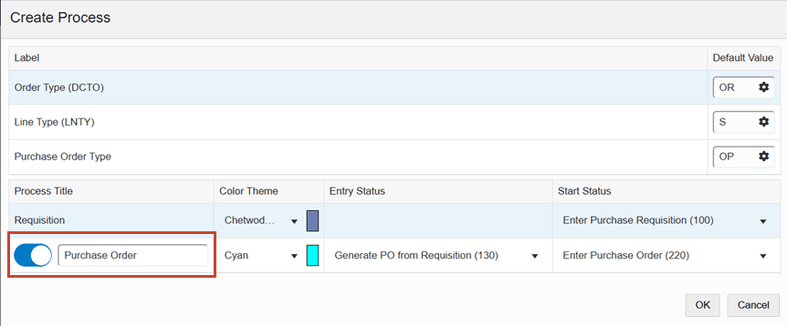
The Create Process window also enables you to choose a color theme for the nodes.
- If the selected template does not contain any connected templates, select the color from the Color Theme drop-down list and select the node from the Start Status drop-down list.
If the selected template contains connected templates, the Create Process window provides the option to disable the connected templates. This option is enabled by default.
In the parent template row, select the color from the Color Theme drop-down list and select the node from the Start Status drop-down list.
In the child template row, you can disable the option to remove the connected template. When the option is enabled, you can select the color from the Color Theme drop-down list and select the node from the Entry Status and Start Status drop-down lists.
The Entry Status node determines the node from where the connected process starts from the parent process. The node you select in the Start Status field becomes the first (start) node in the child process.In the following example, the Purchase Order child process is enabled for the Requisition parent process.
- Click the Configure icon in the Label fields. The User ID option is
selected by default.
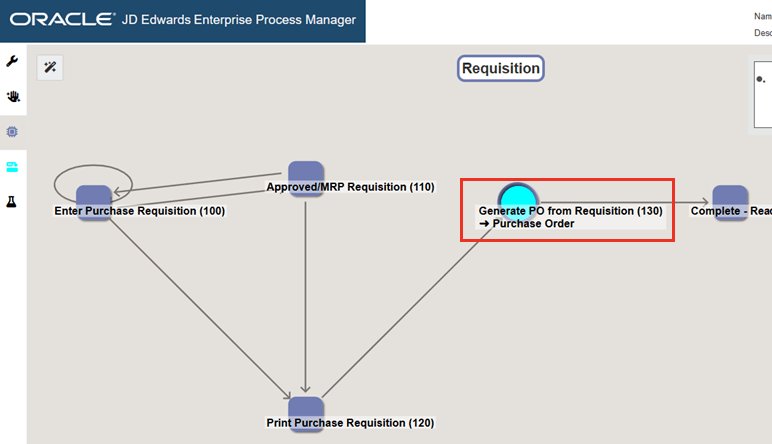
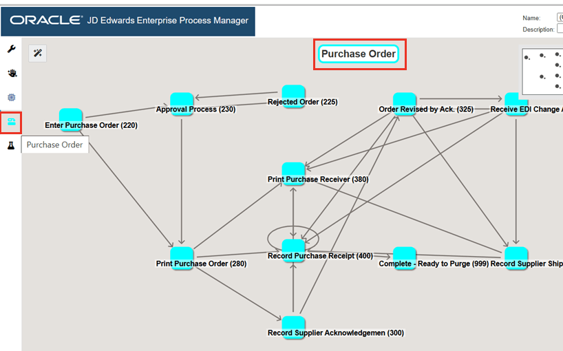
Click OK. The Main Module tab is displayed in the Enterprise Process Manager window, where you can see the automatically generated enterprise process diagram based on the selected template and values defined in the Create Process window.
The nodes represent the tasks in the process template and the links represent the connection between the nodes.
Starting with Tools Release 9.2.9.3, to indicate that a child template is linked to a node, the Enterprise Process Manager shows a circular node in the specified color scheme. In the following example, the name (Requisition) of the parent template is displayed on the generated process diagram. The child template is linked from the Generate PO from Requisition node (indicated by the Cyan color).
Before saving your enterprise process, you can adjust the template and review the configurations to ensure that the data and metrics are defined according to your requirements.
- You can drag and drop the nodes to the required position and use the following
options to adjust the template:Note: You can also use these options to make changes to the enterprise process diagram:
- Snap to Node: Click the Snap to Node icon
 to align the template to the node points.
 - Snap to Grid: Click the Snap to Grid icon
 to align the template to the grid points.
 - Zoom to Fit: Click the Zoom to Fit icon
 to resize the template to fit into the model pane.
You can hold down the Ctrl key when dragging and dropping a node to disable Snap to Grid and Snap to Node features temporarily.
- Snap to Node: Click the Snap to Node icon
Click the Open Process Definition icon
 (next to Design Option) to review the settings in the read-only
mode.
(next to Design Option) to review the settings in the read-only
mode.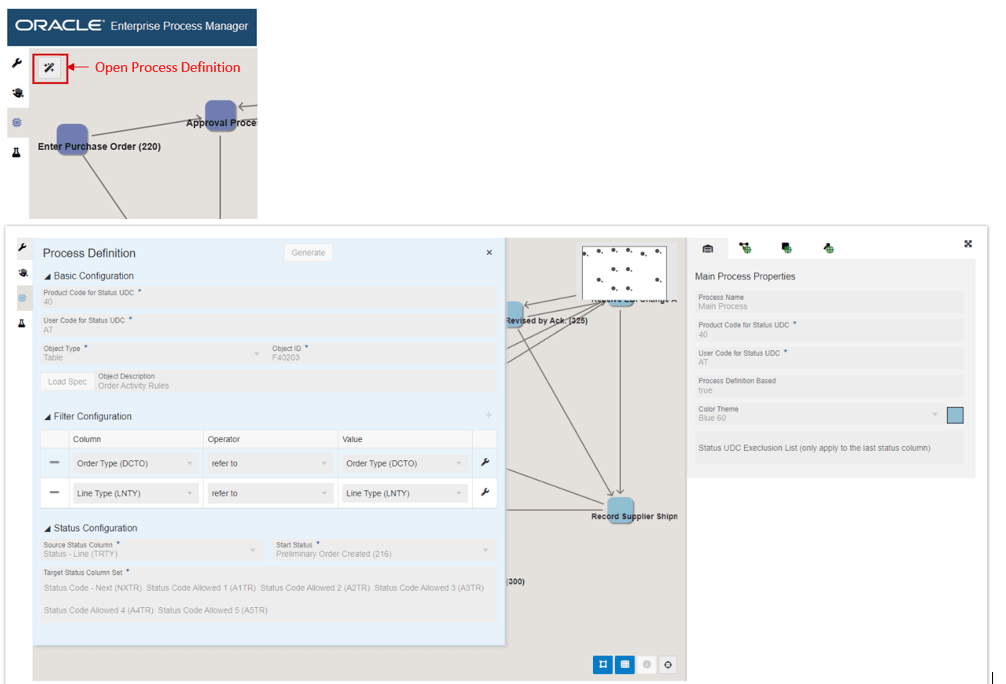
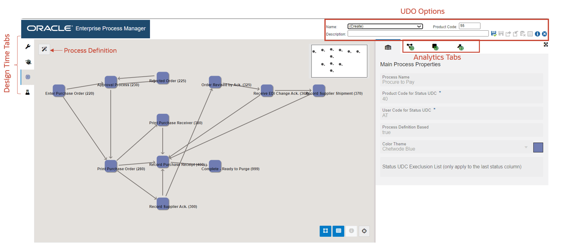
- In the Process Model tab, to review the details of the metrics, click the following
tabs on the right:Note: You can click the subtabs on these tabs to review the table specific metrics and business views. Use Maximize
 or Minimize
  on the tabs to view them in maximized or minimized modes.
- Main Process Properties
 : Displays the process name, status codes, and color themes in
read-only mode.
: Displays the process name, status codes, and color themes in
read-only mode. - Process Metrics
 : Displays tabs with details such as Filter Criteria, Return Fields,
Context Analytics and so on for the related tables and business views of the
selected enterprise process template.
: Displays tabs with details such as Filter Criteria, Return Fields,
Context Analytics and so on for the related tables and business views of the
selected enterprise process template. - Nodes Metrics
 : Displays tabs with details such as Filter Criteria, Return Fields,
Context Analytics and so on for the node specific tables and business
views.
: Displays tabs with details such as Filter Criteria, Return Fields,
Context Analytics and so on for the node specific tables and business
views. - Links Metrics
 : Displays tabs with details such as Filter Criteria, Return Fields,
Context Analytics and so on for the link specific tables and business
views.
: Displays tabs with details such as Filter Criteria, Return Fields,
Context Analytics and so on for the link specific tables and business
views.
- Main Process Properties
- To review the node properties such as Type and UDC status, click the individual
nodes in the process model diagram. The system displays the Selected Node Properties
tab (read-only)
 on the right.
 - To review the link properties, click the individual links in the process model
diagram. The system displays the Selected Link Properties tab (read-only)
 on the right.
 - Click the following tabs on the left to review the details:
- Design Option (read-only)
 : This tab displays the values you entered in the Create Process
window.
: This tab displays the values you entered in the Create Process
window. - Data Filtering and Grouping Options (read-only)
 : This tab displays the template specific data filtering and
grouping options.
: This tab displays the template specific data filtering and
grouping options. -
Process Model (The name of the template is displayed for this tab)
 : This tab displays the automatically generated process model
diagram.
: This tab displays the automatically generated process model
diagram. Starting with Tools Release 9.2.9.3, if a template contains a child template, the system displays a child template tab icon below the Process Model tab icon. This tab displays the automatically generated process model diagram of the child template. The name and the cyan color theme of the child template is displayed for this tab as shown in the following example:
- Preview
 : In this tab, you can preview the runtime view with the current
runtime metrics defined in the selected template. For more information on
how to preview the metrics by using the Preview tab, see Previewing the Enterprise
Process Template.
: In this tab, you can preview the runtime view with the current
runtime metrics defined in the selected template. For more information on
how to preview the metrics by using the Preview tab, see Previewing the Enterprise
Process Template.
- Design Option (read-only)