| C H A P T E R 3 |
|
Attaching Cables and Devices to Modules and Powering On the System Chassis |
This chapter describes how to connect the AC power cables, management network cables, and data network cables to the appropriate chassis modules and how to power on the system for the first time.
This section covers topics listed in the following table.
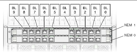
Each NEM connects to all 10 blade slots. The basic NEM provides a 10/100/1000 Ethernet connection for each blade. Other NEMs can provide SAS connectivity to disk blades and 10GbE Ethernet ports, in addition to the 10/100/1000 Ethernet connection for each blade.
The Sun Blade 6000 chassis provides up to two NEM slots per server module labeled NEM 0-1. Slot 0 is the bottom NEM slot and slot 1 being the top NEM slot.
The following illustration shows the Ethernet ports that are associated with each server module for the basic 10/100/1000 Ethernet NEM. The BLx designation refers to the server module slot that corresponds to the Ethernet port.
FIGURE 3-1 Server Module to NEM Correspondence
Refer to the NEM documentation for more information on NEM connections.
|
1. Locate the data network cable.
Refer to the NEM documentation for information on the supported cables for the NEM.
2. Plug the data network cable into the appropriate RJ-45 Ethernet slot or 10 GbE SFP+ connector.
3. Attach the other end of the data network cable to your local area network.
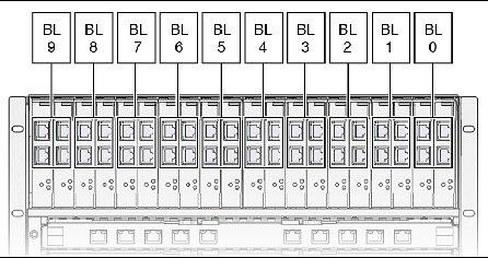
The Sun Blade 6000 chassis provides 20 PCIe EM slots, with two PCIe EM slots assigned to each server module. The PCIe EM slots are numbered PCIe EM 0.0 to 9.1 right-to-left as viewed from the rear of the chassis.
The following illustration shows the Gigabit Ethernet PCIe EMs that correspond with the server modules in the chassis. The BLx designation refers to the server module slot that corresponds to the PCIe EM.
FIGURE 3-2 Server Module to PCIe EM Correspondence
Refer to the PCIe EM documentation for more information on PCIe EM connections.
The following procedure assumes that you have recorded the MAC address for each PCIe EM data port. The PCIe EM port MAC addresses are printed on the PCIe EM board. Refer to the PCIe EM documentation for more information.
|
1. Locate the data network or device cable.
Refer to the PCIe EM documentation for information on the supported cables for the PCIe EM.
2. Attach a cable to the appropriate PCIe EM connector.
3. Attach the other end of the cable to your local area network or storage device.
This section provides instructions for attaching a serial console to the chassis monitoring module (CMM).
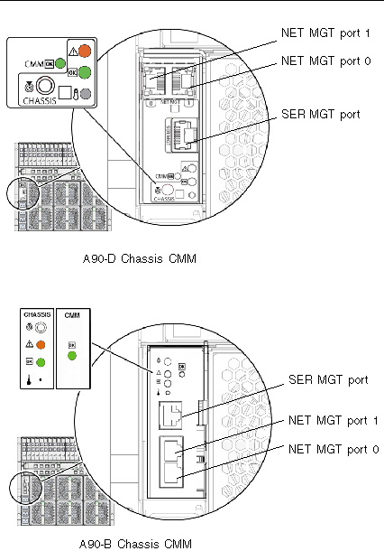
Each chassis contains a CMM with two Ethernet (NET MGT) ports and one serial port (SER MGT) available. FIGURE 3-3 shows the CMM I/O ports. The position of the CMM I/O ports will vary, depending on which version of the Sun Blade 6000 modular system chassis that you have.
The pin assignments for the SER MGT port are shown in TABLE 3-1.
|
1. Connect the following cables to the CMM;
After your initial connection to ILOM, you can also enable the NET MGT
port 1. See the Oracle Integrated Lights Out Manager (ILOM) CMM Administration Guide for more information.
2. Connect the serial cable to a serial device.
3. Attach the Ethernet cable to your local network.
Refer to Configuring the Sun Blade 6000 Modular System Management Network for information on how to configure the CMM ILOM.
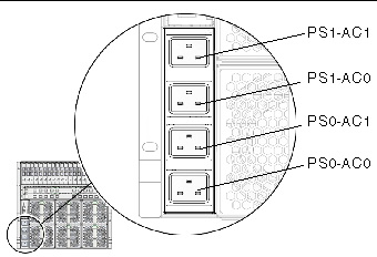
The Sun Blade 6000 chassis includes one AC power interface that provides four power inlets. FIGURE 3-4 shows the AC power connectors.
FIGURE 3-4 AC Power Connectors
The Sun Blade 6000 AC power interface supplies main power to the modules in the system chassis. Main power is automatically applied after the AC power cords are connected from the AC power interface to a customer-supplied power distribution unit (PDU) and the OK power LED flashes.
The AC inlets on the power interface provide power to each power supply unit. All power supply units have separate power cords.
|
1. Locate the four power cables shipped with the system.
2. Locate the AC inlets on the power interface on the rear of the chassis.
3. Open the metal retention clips for each power inlet.
4. In the rear of the chassis, plug four power cables into slot positions: PS0-AC1, PS0-AC0, PS1-AC1, and PS1-AC0.
5. Secure the cable to the connector with the metal retention clip.
6. Plug the other end of the power cables into the power distribution unit (PDU).
Main power is automatically distributed to the system chassis.
Main power is automatically supplied to the system chassis as soon as the power supplies receive power. When the system chassis is powered up, main power is applied to all the modules in the chassis: CMM, NEMs, server modules, and their associated PCIe EMs.
The following procedure describes how to ensure that the system chassis is powered on.
|
1. Ensure that the AC power cables are attached from the power interface module to a power source.
For details, see Cabling the AC Power Interface.
2. Ensure that main power is applied to the system chassis.
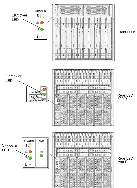
The OK power LED illuminates a solid green light. There are OK power LEDs located on the front and rear of the chassis.
The location of the rear chassis power LEDs will vary, depending on which version of the Sun Blade 6000 chassis that you have. FIGURE 3-5 shows the locations of the front and rear power LEDs.
To ensure that power has been applied to additional chassis modules, see the documentation for each module.
FIGURE 3-5 Front and Rear Chassis LEDs
Copyright © 2010, Oracle and/or its affiliates. All rights reserved.