

|

|
|
|
|
Understanding the Communications Resource Manager
This section discusses the following topics:
Note: All references to ATMI files, functions, and documentation apply to Tuxedo, eLink Platform, and WebLogic Enterprise files, functions, and documentation.
About the Communications Resource Manager
The Communications Resource Manager (CRM) is the component of the BEA eLink Adapter for Mainframe (eAM) that manages communications resources. The CRM coordinates the flow of data between applications running on an ATMI platform and applications running on a mainframe. The mainframe applications may use the following protocols:
The CRM runs as a separate native process providing emulation that allows CICS/ESA and IMS protocols to flow into and out of the ATMI environment.
The CRM must run on the same platform as the SNA stack, but it may run on a different platform from the ATMI system and the eAM gateway (GWSNAX). The eAM gateway provides the configuration for the CRM. If the eAM gateway is to be brought up on a platform other than the one the CRM is on, then the CRM should already be started and monitoring the address specified in the eAM gateway configuration.
System Configuration
The CRM system may be configured as either a local configuration or a distributed configuration running on UNIX, Windows NT, or a mainframe operating system. For a complete list of operating systems, refer to the BEA eLink Adapter for Mainframe Release Notes. If the CRM is not run on a mainframe, it must run on the same platform as the SNA stack. If the eAM gateway is to be brought up on a platform other than the one the CRM is on, then the CRM should already be started and monitoring the address specified in the eAM gateway configuration.
Local Configuration
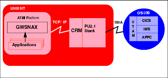
The local configuration, illustrated in Figure 1-1, combines the applications, eAM gateway, ATMI platform, and the CRM with the stack (PU2.1 server) on the same UNIX or Windows NT platform. It employs the IBM proprietary SNA protocol for communication with the mainframe via the stack.
Figure 1-1 eAM Local Configuration

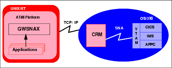
One type of distributed configuration separates the applications and the eAM gateway on a UNIX or Windows NT platform from the CRM by installing the CRM on the IBM OS/390 Mainframe. See Figure 1-2. This configuration eliminates the need for a third-party stack on the UNIX or NT machine. Note that this configuration requires a one-to-one relationship between the local eAM gateway and the remote CRM.
Figure 1-2 eAM Distributed Configuration

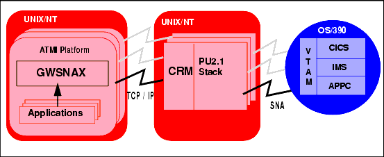
Another type of distributed configuration separates the applications and the eAM gateway from the CRM on different UNIX or Windows NT platforms. See Figure 1-3. This configuration employs Transmission Control Protocol/Internet Protocol (TCP/IP) connectivity between the applications platform and the CRM platforms, as well as the SNA connectivity to the mainframe environment(s). It provides the flexibility to deploy the ATMI platform separately from the CRM with installations that require the ATMI platform on a platform other than the one on which the SNA stack is running. Note that this configuration requires a one-to-one relationship between the local eAM gateway and the remote CRM.
Figure 1-3 Alternate eAM Distributed Configuration

Remote Host Domain Configuration
A basic understanding of the mainframe configuration requirements provides a context for understanding the CRM functions and configuration requirements.
Note: Consult with your local mainframe system administrator for specific information about your system. Any samples provided illustrate a starting point for configuring your system and do not represent all possibilities. The samples represent one way a mainframe can be configured to work in an Advanced Peer-to-Peer Networking (APPN) Local Area Network (LAN) environment.
Ensure that the CICS/ESA remote domain is prepared to conduct operations with the BEA local domain by:
Establishing the VTAM Configuration
If your eAM system is used in a Virtual Telecommunications Access Method (VTAM) environment, make sure the host configuration supports it. Refer to "Sample Configurations" for examples based on the requirements for the eAM.
Configuring the CICS/ESA LU
Before you can connect the CRM to the remote stack, the CICS/ESA LU (Logical Unit) configuration must be established. To accomplish this task, you must create connection definitions, create session definitions, and install resource definitions.
Creating Connections at the Remote Host
If a remote connection definition file is not already in place, you must work with the mainframe support personnel to create one. When placed on the remote host, the definition provides a connection with the local domain. Note the following example of an eAM connection definition file:
DEFINE CONNECTION(BEA)      GROUP(BEACONN)
       DE(eAM EXAMPLE RDO CONNECTION)
       ACCESSMETHOD(VTAM)   PROTOCOL(APPC)
       NETNAME(**VTAM NETWORK NAME OF REMOTE SYSTEM**)
       ATTACHSEC(LOCAL)     AUTOCONNECT(NO)
To install the sample connection definition, put it on the host in a separate group. Use the CEDA INSTALL command.
For example:
CEDA INSTALL GROUP(BEACONN)
Defining the Session at the Remote Host
If a session definition is not already in place, work with the mainframe support personnel to create one. When placed on the remote host, the session definition defines the logical links by which the local domain communicates with the remote host. Note the following example of an eAM session definition:
DEFINE SESSION(BEATEST)       GROUP(BEACONN)
       CONNECTION(BEA)
       DE(eAM EXAMPLE RDO SESSION)
       PROTOCOL(APPC)         AUTOCONNECT(YES)
       MODENAME(**MODE**)     MAXIMUM(**SESSNBR**,**WINNER**)
The arguments and options in this example are defined in the following way:
AUTOCONNECT
YES
MODENAME
MAXIMUM
Viewing Connection and Session Status
After you have installed group definitions, you can view the status of connections and sessions using the following CICS/ESA system commands:
CEMT I CONN(BEA)            **view the status of the connection
CEMT I NET(**Netname**)     **View the status of the sessions
CEMT I MODENAME(**MODE**)   **View the status of the mode
Completing Cross-Platform Definitions
Consult with your CICS/ESA remote domain administrator to obtain key parameters in the VTAM definition that must be included in the SNA stack configuration, as well as in other configuration files in the eAM local domain.
VTAM Cross-Platform Definitions
Before installing eAM software, please review Table 1-1 for a summary of cross-platform definitions. Consult with the VTAM system administrator to obtain the value indicated in the Name column and make the corresponding entries shown in the Needed In column.
DCL-based stacks referred to in Table 1-1 include the following stacks:
.
|
Name |
Originates In |
Needed In |
|---|---|---|
|
SNA Network ID and VTAM Host ID |
VTAM configuration |
SunLink SNA Stack Configuration: DCL-based Stack Configuration: Example: |
|
Mode Name |
VTAM-MODEENT definition |
CICS Sessions Definition: SunLink SNA Stack Configuration: DCL-based Stack Configuration: GWSNAX Configuration: |
|
Control Point Name |
VTAM-PU definition |
SunLink SNA Stack Configuration: DCL-based Stack Configuration: |
|
Local LU Name |
VTAM-LU definition |
CICS CONNECTION definition: DCL-based Stack Configuration: GWSNAX Configuration: |
|
CICS LU Name |
VTAM-LU definition |
SunLink SNA Stack Configuration: DCL-based Stack Configuration: GWSNAX Configuration: |
|
Terminal Identifier |
VTAM |
SunLink SNA Stack Configuration: DCL-based Stack Configuration: |
|
Local Network Device |
UNIX Configuration |
SunLink SNA Stack Configuration: |
|
Local MAC Address |
Token ring address of Host |
SunLink SNA Stack Configuration: |
|
Remote MAC Address (token ring only) |
Token ring address of local machine |
SunLink SNA Stack Configuration: DCL-based Stack Configuration: |
|
LAN Speed |
Speed of token ring network |
SunLink SNA Stack Configuration: |
|
SDLC parameters (line protocol) |
VTAM-line definition |
SunLink SNA Stack Configuration: |
|
Partner Definition (e.g. TUXPART1) |
CICS/ESA |
Mainframe Client Application: |
|
Set LU definition so maximum sync-level allowed corresponds to DMCONFIG file entry: |
Stacks |
SunLink SNA Stack Configuration: DCL-based Stack Configuration: |
|
Map all incoming conversations to eAM gateway (make sure TPs have all privileges available, e.g. CNOS, syncpoint if licensed, service conversations, etc.). |
Stacks |
SunLink SNA Stack Configuration: DCL-based Stack Configuration: |
|
CICS Transaction IDs (e.g. TOUP) |
CICS/ESA |
GWSNAX Configuration: |
OS/390 UNIX Platform Definitions
Before installing eAM software, please review Table 1-2 for a summary of SNA definitions when CRM runs on an OS/390 UNIX platform. Consult with the system administrator to obtain the value indicated in the Name column and make the corresponding entries shown in the Needed In column.
.
|
Name |
Originates In |
Needed In |
|---|---|---|
|
Local LU Name |
VTAM-LU definition |
CICS CONNECTION definition: |
|
Mode Name |
VTAM-MODEENT definition |
CICS Sessions Definition: |
|
CICS LU Name |
VTAM-LU definition |
GWSNAX Configuration: |
|
Maximum sync-level allowed |
Stacks |
VTAM Configuration: GWSNAX Configuration: |
|
CICS Transaction IDs (e.g. TOUP) |
CICS/ESA |
GWSNAX Configuration: |
Microsoft SNA Cross-Platform Definitions
Be sure to communicate with the administrator of the CICS/ESA remote domain to obtain key parameters in the VTAM definition that must be included in the Microsoft SNA Server configuration, as well as in other configuration files in the eAM local domain.
Before installing eAM software, please examine the following general procedure for configuring the Microsoft SNA Server. Use the Microsoft SNA Server Manager. Sample values are shown in parenthesis. Consult with the VTAM system administrator to obtain the proper values.
In the Link Service Properties, define DLC 802.2 Link Service Configuration:
In the MVSNT1 Properties, define:
General
Address
System Identification
802.2 DLC
General
Advanced
General
Options
General
Limits
Characteristics
Partners
Compression

|

|

|
|
|
|
Copyright © 2001 BEA Systems, Inc. All rights reserved.
|