3 Server Components and Features
This section describes the components, status indicators (LEDs), connectors, ports, and storage drives on the front and back panels of the servers.
Note:
For more information on controls, connectors, LEDs, system components, and replaceable components of the server, refer to:
-
Oracle Server X9-2 Documentation Oracle Server X9-2 Service Manual - About the Oracle Server X9-2
-
Oracle Server X9-2L Documentation Oracle Server X9-2L Service Manual - About the Oracle Server X9-2L
Server Components
The following tables list system components for Oracle Server X9-2 and Oracle Server X9-2L.
Oracle Server X9-2 Components
| Feature | Oracle Server X9-2 System Components |
|---|---|
|
System chassis |
1U chassis (Oracle Server X9-2) |
|
Processor |
One or two processors with eight memory channels per processor, 16 DIMMs per processor. Processors with the following capabilities are supported (factory installed) in Oracle Server X9-2:
For the latest information on processor specifications, go to Oracle x86 Servers and navigate to the Oracle Server X9-2 page. |
|
Memory |
|
|
Storage Drives |
Oracle Server X9-2 storage drive configuration can comprise solid state drives (SSDs). The configuration includes:
|
|
PCI Express (PCIe) slots |
|
|
I/O ports |
|
|
USB 3.0 ports |
One USB 3.0 port on Oracle Server X9-2 back panel. |
|
Service processor (SP) |
Oracle Server X9-2 has an integrated service processor (SP). SP features include:
|
|
Management software |
|
|
Power supplies |
Two hot-swappable and highly-redundant 1200W A269.2 or 1400W A271 power supplies. For Oracle Server X9-2 supported power supply information, refer to Oracle Server X9-2 Documentation Product Notes - Supported Power Supplies. |
|
Cooling fans |
Four hot-swappable fan modules, each containing two 40x56 mm counter-rotating fans. |
|
Operating systems and virtualization software |
For Oracle Server X9-2 supported OS release information, refer to Oracle Server X9-2 Documentation Product Notes - Supported Operating Systems. |
Oracle Server X9-2L Components
| Feature | Oracle Server X9-2L System Components |
|---|---|
|
System chassis |
2U chassis (Oracle Server X9-2L) |
|
Processor |
One or two processors with eight memory channels per processor, 16 DIMMs per processor. Processors with the following capabilities are supported (factory installed) in Oracle Server X9-2L:
For the latest information on processor specifications, go to Oracle x86 Servers and navigate to the Oracle Server X9-2L page. |
|
Memory |
|
|
Storage Drives |
Oracle Server X9-2L storage drive configuration can comprise both hard disk drives (HDDs) or solid state drives (SSDs). The configuration includes:
An NVM-Express PCIe x16 retimer card is required for storage drive configurations that contain NVMe SSDs in drive bays 8 through 11. |
|
PCI Express (PCIe) slots (Oracle Server X9-2L) |
|
|
I/O ports (Oracle Server X9-2L) |
|
|
USB 3.0 ports |
One USB 3.0 port on Oracle Server X9-2L back panel. |
|
Service processor (SP) |
Oracle Server X9-2L has an integrated service processor (SP). SP features include:
|
|
Management software |
Servers Documentation Systems Management.
|
|
Power supplies |
Two hot-swappable and highly-redundant 1200W A269.2 or 1400W A271 power supplies. For Oracle Server X9-2L supported power supply information, refer to Oracle Server X9-2L Documentation Product Notes - Supported Power Supplies. |
|
Cooling fans |
Four hot-swappable fan modules, each containing an 80x56 mm counter-rotating dual motor fan. |
|
Operating systems and virtualization software |
For Oracle Server X9-2L supported OS release information, refer to Oracle Server X9-2L Documentation Product Notes - Supported Operating Systems. |
X9-2 Front Panel Features
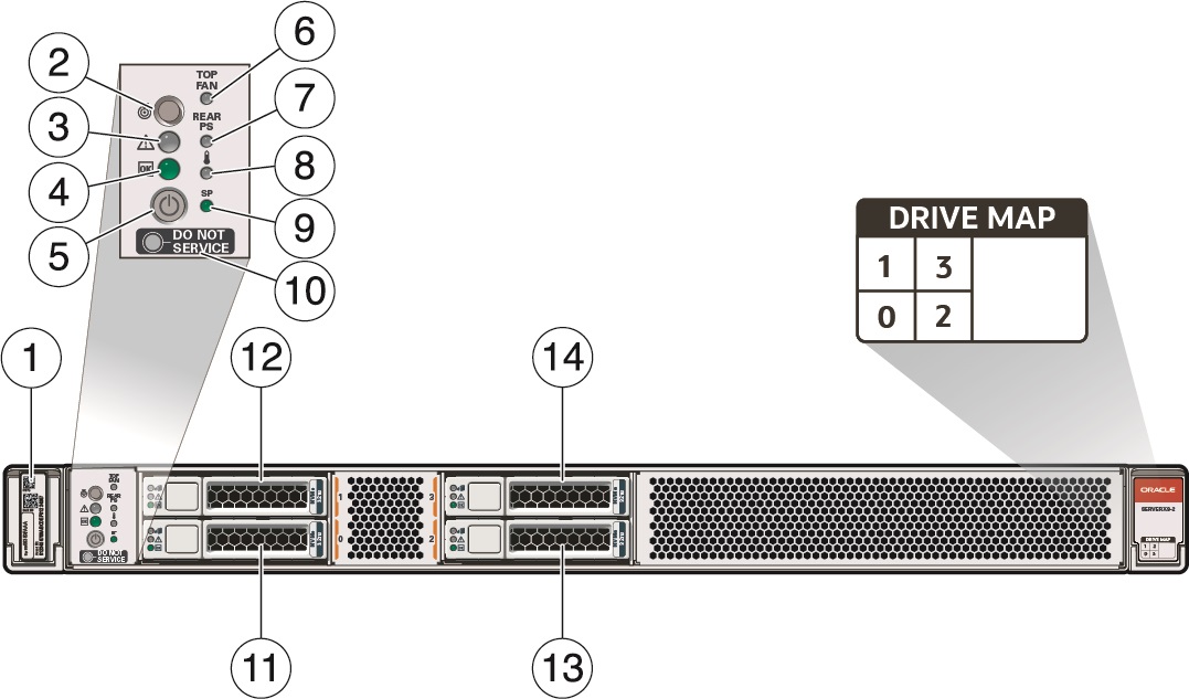
The following figure shows the status indicators (LEDs), connectors, and storage drives located on the front panel of Oracle Server X9-2 with four 2.5-inch storage drives.
For information about how to interpret the status indicators (LEDs), refer to Oracle Server X9-2 Documentation Oracle Server X9-2 Service Manual - Front and Back Panel Components.

| Call Out | Description |
|---|---|
|
1 |
Product Serial Number (PSN) label and Radio Frequency Identification (RFID) tag |
|
2 |
Locate LED/button: white |
|
3 |
Fault - Service Required LED: amber |
|
4 |
System OK LED: green |
|
5 |
On/Standby button |
|
6 |
Service Required LED: Top Fan Module: amber |
|
7 |
Service Required LED: Back panel Power Supply: amber |
|
8 |
Service Required LED: Overtemp Icon, System Over Temperature Warning: amber |
|
9 |
SP OK LED: green |
|
10 |
Do Not Service Indicator: white |
|
11 |
Storage drive 0 SSD/NVMe |
|
12 |
Storage drive 2 SSD/NVMe |
|
13 |
Storage drive 1 SSD/NVMe |
|
14 |
Storage drive 3 SSD/NVMe |
X9-2 Back Panel Features
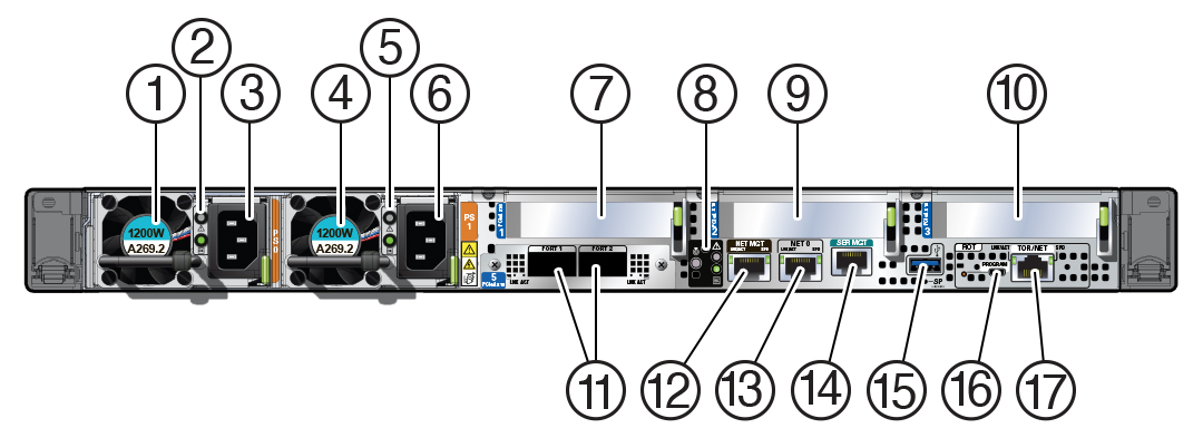
The following figure shows the Oracle Server X9-2 back panel and the location of status indicators (LEDs), connectors, and PCIe slots.
For information about how to interpret the status indicators (LEDs), refer to Oracle Server X9-2 Documentation Oracle Server X9-2 Service Manual - Front and Back Panel Components.

| Call Out | Description |
|---|---|
|
1 |
PS0 Power Supply (PS) 0 |
|
2 |
PS0 status indicators: Fault-Service Required LED: amber; AC OK LED: green |
|
3 |
PS0 AC power inlet |
|
4 |
PS1 Power Supply (PS) 1 |
|
5 |
PS1 status indicators: Fault-Service Required LED: amber; AC OK LED: green |
|
6 |
PS1 AC power inlet |
|
7 |
PCIe card slot 1 (nonfunctional in single-processor systems) |
|
8 |
System status indicators: Locate Button/LED: white; Fault-Service Required LED: amber; System OK LED: green |
|
9 |
PCIe card slot 2 |
|
10 |
PCIe card slot 3 |
|
11 |
OCPNIC QSPF: Two QSFP 28/56 GbE Ethernet connectors for the Ethernet controller. (Optional) 10/25/50/100/200 Gbs Open Compute Project (OCP) Version 3.0 (V3) Network Interface Card (NIC) with two QSFP ports (PORT 1 and PORT 2) |
|
12 |
NET MGT: Oracle Integrated Lights Out Manager (ILOM) service processor (SP) network management (NET MGT) RJ-45 100/1000BASE-T port |
|
13 |
NET0: Network (NET) 100/1000BASE-T RJ-45 Gigabit Ethernet (GbE) host management port One 1 Gbps Host Management RJ-45 connector connected to the on-board Ethernet controller |
|
14 |
SER MGT: Serial management RJ-45 serial Ethernet port (CLI) |
|
15 |
USB 3.0 connector |
|
16 |
Not used, blank plate |
|
17 |
Not used, blank plate |
X9-2L Front Panel Features
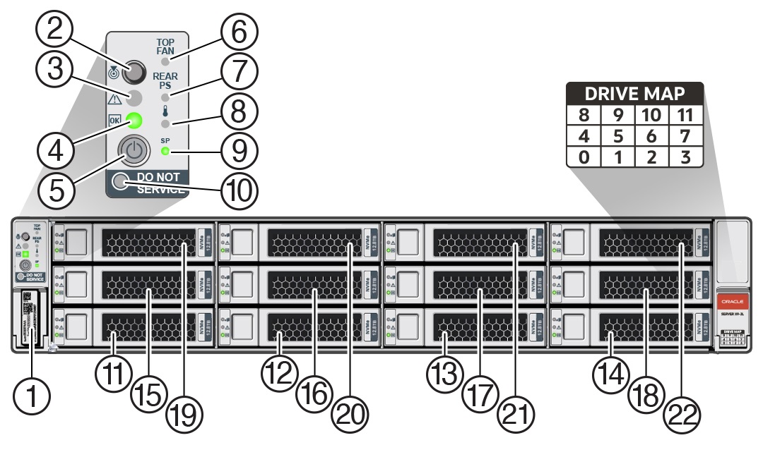
The following figure shows the status indicators (LEDs), connectors, and drives located on the front panel of Oracle Server X9-2L configured with twelve 3.5-inch storage drives.
For information about how to interpret the status indicators (LEDs), refer to Oracle Server X9-2L Documentation Oracle Server X9-2L Service Manual - Front and Back Panel Components.

| Call Out | Description |
|---|---|
|
1 |
Product Serial Number (PSN) label and Radio Frequency Identification (RFID) tag |
|
2 |
Locate LED/button: white |
|
3 |
Fault - Service Required LED: amber |
|
4 |
System OK LED: green |
|
5 |
On/Standby button |
|
6 |
Service Required LED: Top Fan Module: amber |
|
7 |
Service Required LED: Back panel Power Supply: amber |
|
8 |
Service Required LED: Overtemp Icon, System Over Temperature Warning: amber |
|
9 |
SP OK LED: green |
|
10 |
Do Not Service Indicator: white |
|
11 |
Storage drive 0 HDD/SSD/NVMe |
|
12 |
Storage drive 1 HDD/SSD/NVMe |
|
13 |
Storage drive 2 HDD/SSD/NVMe |
|
14 |
Storage drive 3 HDD/SSD/NVMe |
|
15 |
Storage drive 4 HDD/SSD/NVMe |
|
16 |
Storage drive 5 HDD/SSD/NVMe |
|
17 |
Storage drive 6 HDD/SSD/NVMe |
|
18 |
Storage drive 7 HDD/SSD/NVMe |
|
19 |
Storage drive 8 HDD/SSD/NVMe |
|
20 |
Storage drive 9 HDD/SSD/NVMe |
|
21 |
Storage drive 10 HDD/SSD/NVMe |
|
22 |
Storage drive 11 HDD/SSD/NVMe |
X9-2L Back Panel Features
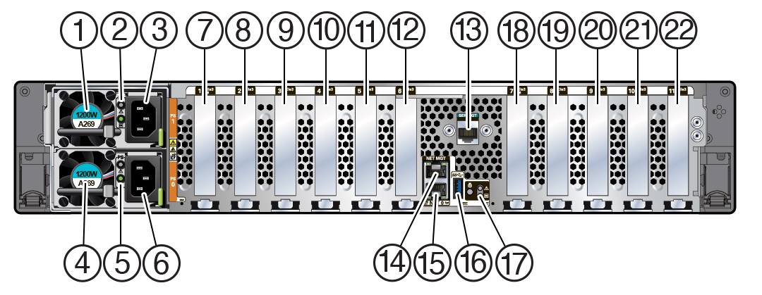
This section shows Oracle Server X9-2L back panel and the location of status indicators (LEDs), connectors, and PCIe slots.
For information about how to interpret the status indicators (LEDs), refer to Oracle Server X9-2L Documentation Oracle Server X9-2L Service Manual - Front and Back Panel Components.
