Single 4-Socket (1x4) Server
For the single 4-socket (1x4) server configuration:
-
System Module (SMOD) SMOD0 System A and SMOD1 System B must be installed, but only SMOD0 is active.
-
CPU modules (CMODs) must be installed in slots 0-3. CMOD slots 4-7 are empty.
-
All eight dual PCIe card carrier (DPCC) slots must be installed but only DPCC slots 1, 2, 3 and 4 are active.
PCIe slots 5, 6, 7, and 8 are nonfunctional in 4-socket systems.
-
All eight fan modules (FMs) must be installed but only FMs 0-3 are active.
-
Both fan frames must be installed.
-
PS2 and PS3 are installed and active. PS0 and PS1 are also installed, but inactive. PS2 and PS3 power System A. PS0 and PS1 power System B.
All four AC power connectors on the back panel must be attached with grounded AC power cords.
-
Storage drive bays in System B may have filler panels installed.
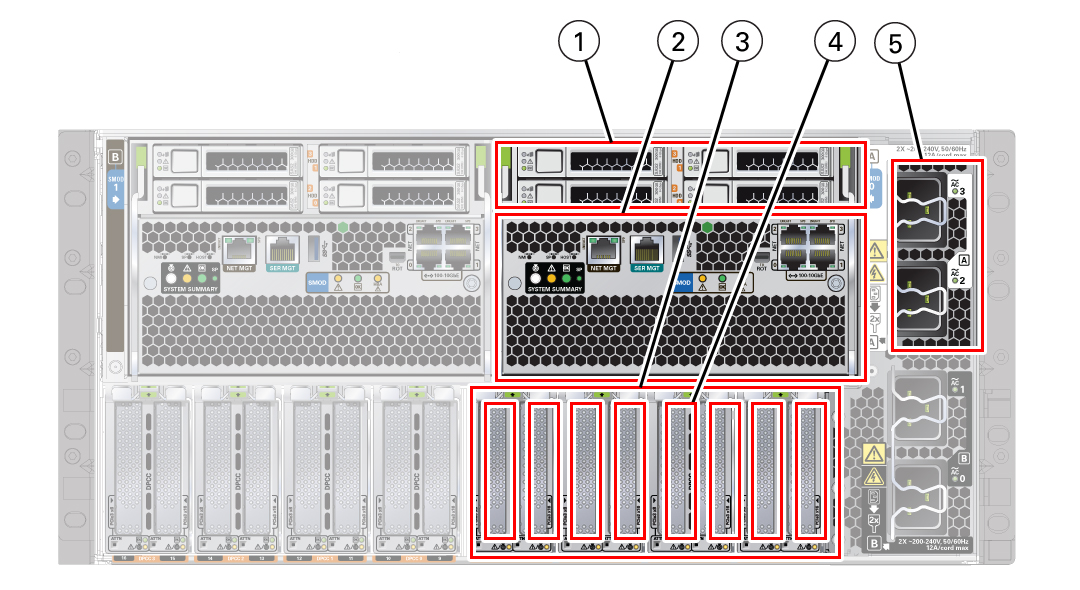
The following illustration shows an Oracle Server X8-8 back panel with a single 4-socket (1x4) server four-CMOD configuration.

| Call Out | Description |
|---|---|
|
1 |
HDD0-3 four storage drives, back panel accessible |
|
2 |
SMOD0 System A |
|
3 |
PCIE1-8 System A |
|
4 |
DPCC0-3 System A |
|
5 |
AC Inlets 2, 3 System A |
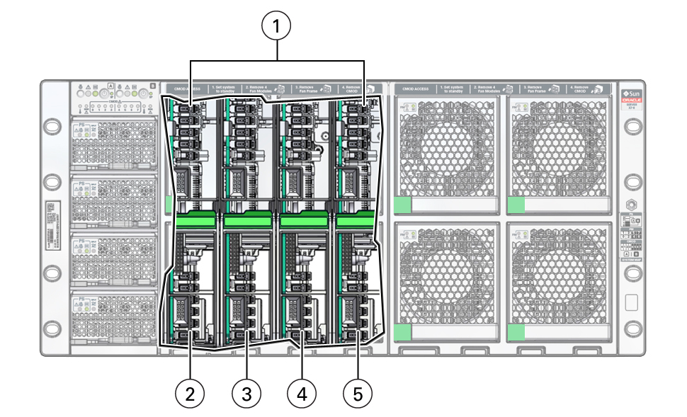
The following illustration shows an Oracle Server X8-8 front panel with a single 4-socket (1x4) server four-CMOD configuration. In the four-CMOD configuration, the first four slots on the left (slots 0-3) are occupied and the four slots on the right (4-7) are unoccupied. In the illustration, the front panel left-side fan modules and fan frame have been removed to show the four active CMODs behind the fan frame. Call out 1 identifies the group of four active CMODs.

| Call Out | Description |
|---|---|
|
1 |
System A: four active CMODs behind fan frame, front panel accessible |
|
2 |
CMOD0 System A |
|
3 |
CMOD1 System A |
|
4 |
CMOD2 System A |
|
5 |
CMOD3 System A |
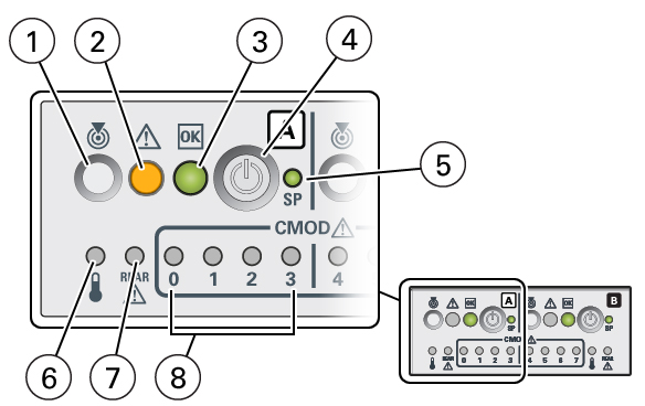
For servers with a single 4-socket (1x4) server configuration, the FIM provides controls and indicators for System A (SMOD0) only. The following illustration shows an Oracle Server X8-8 front panel FIM with a single 4-socket (1x4) server configuration.

| Call Out | Description |
|---|---|
|
1 |
Locate button/LED (chassis SMOD0 System A) |
|
2 |
Fault-Service Required (chassis SMOD0 System A) |
|
3 |
System OK (chassis SMOD0 System A) |
|
4 |
On/Standby button chassis SMOD0 System A (recessed) |
|
5 |
SP OK (chassis SMOD0 System A) |
|
6 |
System Overtemperature Warning (chassis SMOD0 System A) |
|
7 |
Rear Fault-Service Required LED (chassis SMOD0 System A) |
|
8 |
CMOD Fault-Service Required LEDs 0, 1, 2, 3 |