Dual 4-Socket (2x4) Servers
For the dual 4-socket server configuration:
-
System Module 0 (SMOD0) System A and SMOD1 System B must be installed.
-
CPU Modules (CMODs) must be installed in slots 0-7.
-
Dual PCIe card carrier (DPCC) slots 0-3 and DPCC slots 4-7 must be installed and are active.
-
All eight fan modules (FMs) must be installed. All FMs must be active in the dual 4-socket configuration.
-
Both fan frames must be installed.
-
PS2 and PS3 are installed and active. PS0 and PS1 are also installed and active. PS2 and PS3 power System A. PS0 and PS1 power System B.
-
All four AC power connectors on the back panel must be attached with grounded AC power cords.
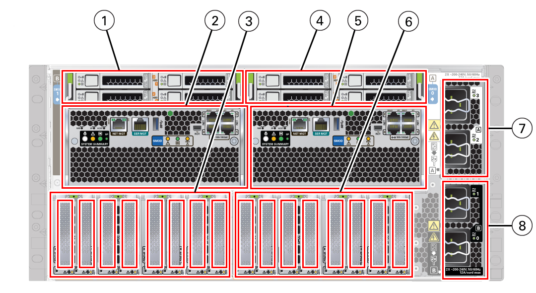
The following illustration shows an Oracle Server X8-8 back panel with a dual 4-socket configuration.

| Call Out | Description |
|---|---|
|
1 |
HDD0-3 System B |
|
2 |
SMOD1 System B |
|
3 |
PCIe Slots 9-16 System B |
|
4 |
HDD0-3 System A |
|
5 |
SMOD0 System A |
|
6 |
PCIe Slots 1-8 System A |
|
7 |
AC Power System A: 3, 2 |
|
8 |
AC Power System B: 1, 0 |
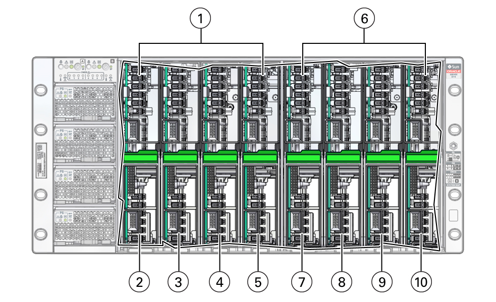
The following illustration shows an Oracle Server X8-8 front panel with a dual 4-socket configuration.

| Call Out | Description |
|---|---|
|
1 |
System A |
|
2 |
CMOD0 System A |
|
3 |
CMOD1 System A |
|
4 |
CMOD2 System A |
|
5 |
CMOD3 System A |
|
6 |
System B |
|
7 |
CMOD4 System B |
|
8 |
CMOD5 System B |
|
9 |
CMOD6 System B |
|
10 |
CMOD7 System B |
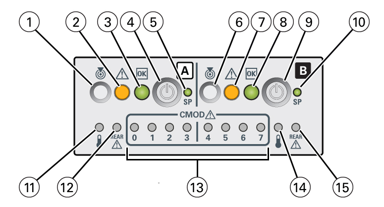
For servers with a dual 4-socket configuration, the FIM provides separate controls and indicators for System A (SMOD0) and System B (SMOD1).
The following illustration shows an Oracle Server X8-8 front panel FIM with a dual 4-socket configuration.

| Call Out | Description |
|---|---|
|
1 |
Locate button/LED (chassis SMOD0 System A) |
|
2 |
Fault-Service Required (chassis SMOD0 System A) |
|
3 |
System OK (chassis SMOD0 System A) |
|
4 |
On/Standby button (chassis SMOD0 System A) (recessed) |
|
5 |
SP OK (chassis SMOD0 System A) |
|
6 |
Locate button/LED (SMOD1 System B) |
|
7 |
Fault-Service Required (SMOD1 System B) |
|
8 |
System OK (SMOD1 System B) |
|
9 |
On/Standby button SMOD1 System B (recessed) |
|
10 |
SP OK (SMOD1 System B) |
|
11 |
System Overtemperature Warning (SMOD0 System A) |
|
12 |
Rear Fault-Service Required LED (SMOD0 System A) |
|
13 |
CMOD Fault-Service Required LEDs (chassis SMOD0 System A: 0, 1, 2, 3, and SMOD1 System B: 4, 5, 6, 7) |
|
14 |
System Overtemperature Warning (SMOD1 System B) |
|
15 |
Rear Fault-Service Required LED (SMOD1 System B) |