Illustrated Parts Breakdown
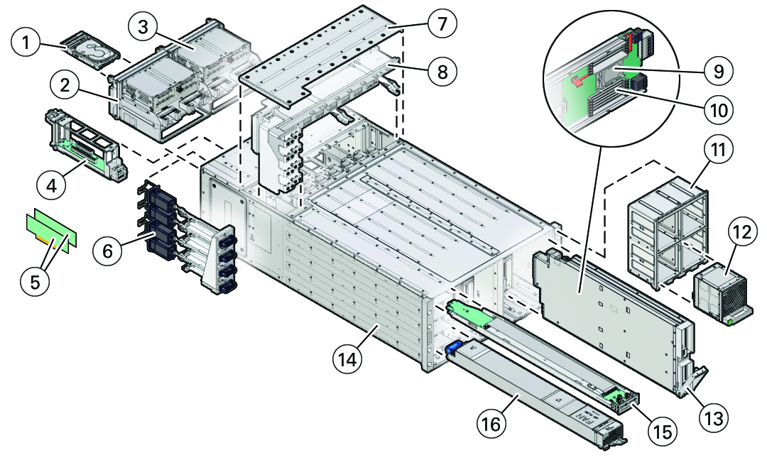
The following illustration identifies the major components of the server.

| Call Out | Description | Links |
|---|---|---|
|
1 |
Storage drives (8), back panel accessible |
|
|
2 |
System Module 0 (SMOD0), back panel accessible |
|
|
3 |
System Module 1 (SMOD1), back panel accessible |
|
|
4 |
Dual PCIe carrier card (DPCC) with PCIe cards (8) |
|
|
5 |
PCIe cards (DPCC slots 4-7 and PCIe slots 9-16 are nonfunctional in 4-socket systems.) |
|
|
6 |
AC power block The AC power block is not a removable component. |
|
|
7 |
Top access panel |
|
|
8 |
Midplane assembly |
|
|
9 |
Processor, front panel accessible |
|
|
10 |
Memory, front panel accessible |
|
|
11 |
Fan frame (2), front panel accessible |
|
|
12 |
Fan module (FM) (8), front panel accessible |
|
|
13 |
CPU module (CMOD) (4 or 8), front panel accessible |
|
|
14 |
Server chassis The server chassis is not a removable component. |
|
|
15 |
Front indicator module (FIM), front panel accessible |
|
|
16 |
Power supply (PSU) (4), front panel accessible |