Power Subsystem
Use the Oracle Integrated Lights Out Manager (ILOM) Power page to view the overall health and power consumption of the power supplies installed in your system. Review the Power Supplies table for details about the health and location of individual power supplies.
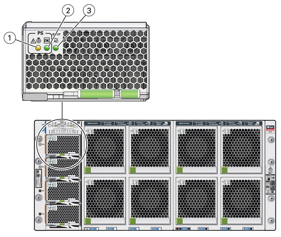
Chassis power is provided by four hot-serviceable front panel accessible power supply units (PSUs). The four PSUs provide dual (1+1) redundancy. Therefore, the minimum PSU configuration is two. To ensure redundancy, at least two separate circuits should supply server power. The following figure shows the indicator panel on the front of the power supplies.

| Call Out | Status LED or Button | Icon and Color | Description |
|---|---|---|---|
|
1 |
Fault-Service Required
Locate LED |
Amber White |
Indicates the location of the power supply in the server:
Lights steady on when the power supply is in a fault state. |
|
2 |
OK Power Supply OK LED |
Green |
Indicates the functional state of the power supply:
Note: Oracle ILOM signals a fault on any installed power supply that is not connected to an AC power source, since it might indicate a loss of redundancy. |
|
3 |
AC OK LED |
~AC Green |
Indicates the operational state of the power supply:
|
Each power supply is rated for 3060W continuous output. Input is 220V VAC only (50-60Hz). Main output is 12V @244A. Standby output is 12V at 5A. The MAX input line current (200-277 VAC input) is less than 16 Amps RMS. The minimum holdup is 12ms for Main output and 40ms for Standby.
When the AC power cords are connected to AC inputs at the back of the chassis, the power supplies supply power to the Ethernet ports, the system sensors and inventory circuits, and the service processor (SP). When power is supplied to the SP, the SP boots, and the server enters the low-power Standby power mode.
Once the SP boots into Standby power, Main power is initiated by pressing and releasing the chassis front panel On/Standby button or by powering on the server remotely from Oracle ILOM.
For more information about power control, see Power Control, Shutdown, and Reset States.
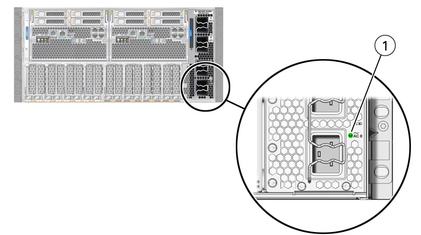
In the following figure, callout 1 shows the AC OK indicator for inlet ~AC 0.

| Call Out | Status LED or Button | Icon and Color | Description |
|---|---|---|---|
|
1 |
AC OK LED |
~AC Green |
Indicates the operational state of the power supply:
|