Front Panel Components
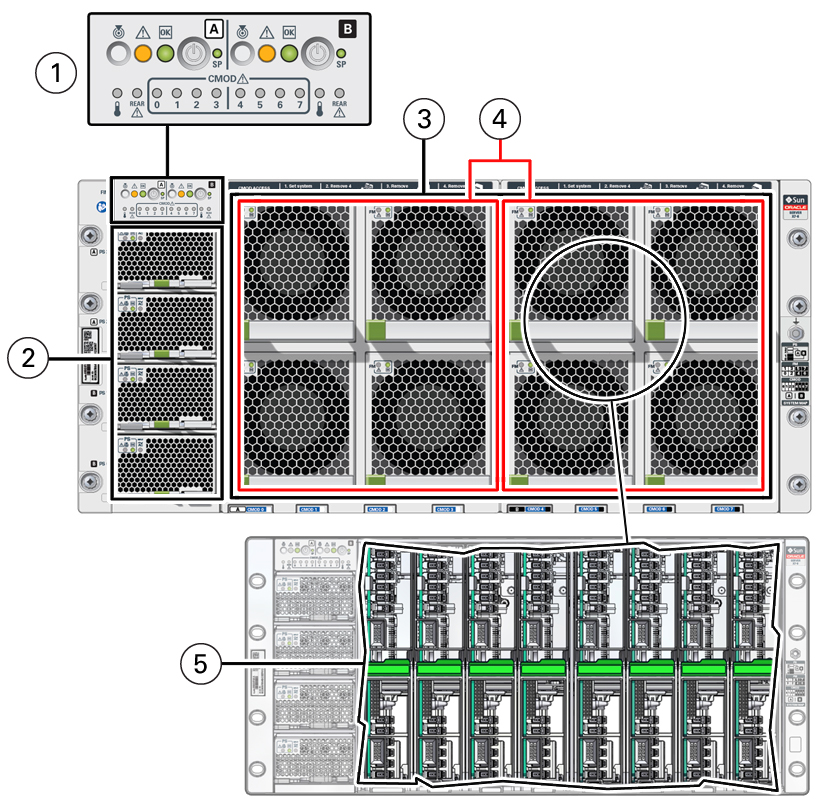
The following figure shows the Oracle Server X8-8 chassis front panel components:

| Call Out | Component | Link |
|---|---|---|
|
1 |
Front indicator module (FIM). The FIM provides separate controls and system status LED indicators for System A and System B while in 4-socket mode.
|
|
|
2 |
Four power supplies (PS) Power supplies 0 (bottom) through 3 (top) labeled PS0, PS1, PS2, PS3 PS2 and PS3 power System A. PS0 and PS1 power System B. |
|
|
3 |
Eight fan modules (FM) Fan modules FM0 through FM7: Top row: 1, 3, 5, 7 Bottom row: 0, 2, 4, 6 SMOD0 System A: FM 0, 1, 2, 3; SMOD1 System B: FM 4, 5, 6, 7 |
|
|
4 |
Two fan frames SMOD0 System A: FM 0, 1, 2, 3; SMOD1 System B: FM 4, 5, 6, 7 |
|
|
5 |
Eight internal CPU Modules (CMODs). CMOD bays are accessible behind the fan frames. System A: CMODs 0-3; System B: CMODs 4-7. 4-socket mode: CMODs 0-3. 8-socket mode: CMODs 0-7 |
For component serviceability, locations, and designations, see Replaceable Components.