3 Understanding the WebCenter Portal Enterprise Deployment Topology
This chapter describes the WebCenter Portal deployment topologies. These topologies represent specific reference implementations of the concepts described in Understanding a Typical Enterprise Deployment.
This chapter provides information on primary WebCenter Portal topology diagrams.
- Diagram of the WebCenter Portal Enterprise Deployment Topology
- Understanding the Primary WebCenter Portal Topology Diagrams
- Flow Charts and Roadmaps for Implementing the Primary WebCenter Portal Enterprise Topologies
Parent topic: Understanding an Enterprise Deployment
Diagram of the WebCenter Portal Enterprise Deployment Topology
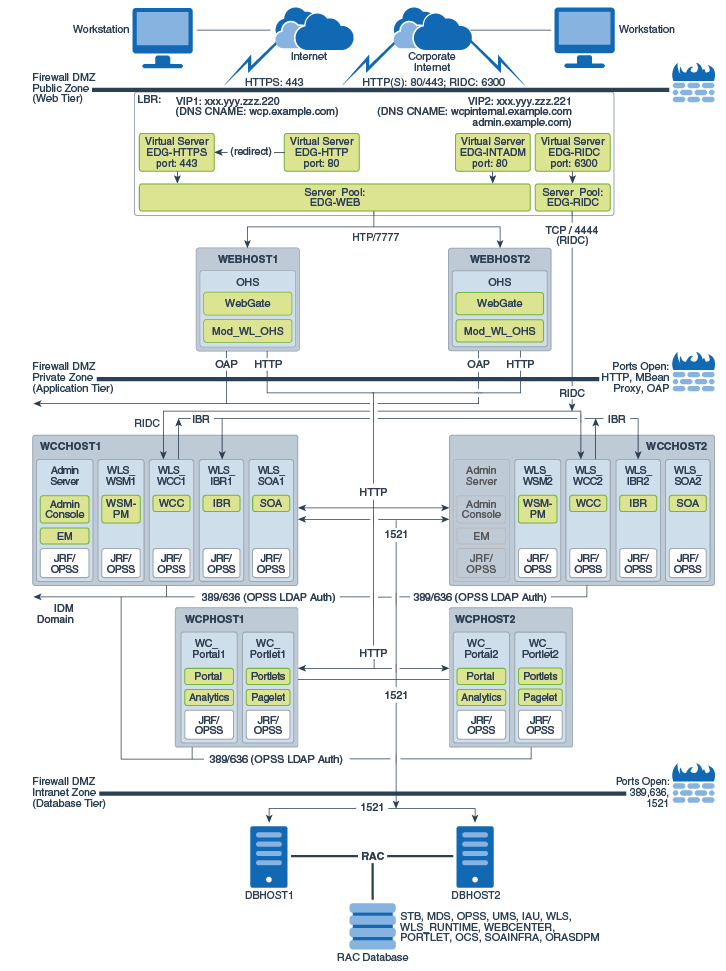
The following diagram shows the primary Oracle WebCenter Portal enterprise deployment topology, which is described in this guide.

Description of the illustration wcedg-wc-portal-topology-diagram.eps
Understanding the Primary WebCenter Portal Topology Diagrams
The Oracle WebCenter Portal topology follows a standard approach to an enterprise topology based on Oracle-recommended best practices. The standard elements of an Oracle Fusion Middleware enterprise topology are described in detail in Understanding a Typical Enterprise Deployment.
Before you review the information here, it is assumed you have reviewed the information in Understanding a Typical Enterprise Deployment and that you are familiar with the general concepts of an enterprise deployment topology.
See the following sections for information about the elements that are unique to the topology described in this chapter:
Summary of the WebCenter Portal Load Balancer Virtual Server Names
In order to balance the load on servers and to provide high availability, the hardware load balancer is configured to recognize a set of virtual server names.
For information about the purpose of each of these server names, see Summary of the Typical Load Balancer Virtual Server Names.
The following virtual server names are recognized by the hardware load balancer in Oracle WebCenter Portal topologies:
-
wcp.example.com— This virtual server name is used for all incoming end-user client traffic. It acts as the access point for all HTTP traffic to the run-time WebCenter Portal components. The load balancer listens for all requests to this virtual server name over SSL. Optionally, an additional virtual server configured on port 80 can be set up with a rule to automatically redirect all traffic to port443. As a result, clients access this environment's services using the following secure address:https://wcp.example.com:443
-
wcpinternal.example.com — This virtual server name is used for internal calls to Oracle WebCenter services. There are two virtual servers configured at the hardware load balancer. One (listening on port 80) is used for web-based services. The second (listening on port 6300) is for WebCenter Conent Remote Intradoc Client (RIDC) API calls.
Incoming traffic from clients is not SSL-enabled. Clients accessing the HTTP services use the following address. These requests are forwarded to port 7777 on WEBHOST1 and WEBHOST2:
http://wcpinternal.example.com:80/...
WebCenter Content RIDC-enabled applications, such as the WebCenter Content Desktop Integration Suite (DIS) and WebCenter Portal Document Services, use port 6300 for TCP connections to WebCenter Content Server's RIDC API endpoints. These requests are forwarded to port 4444 on WCCHOST1 and WCCHOST2:
wcpinternal.example.com:6300
-
admin.example.com- This virtual server name is for administrators who need to access the Oracle Enterprise Manager Fusion Middleware Control and Oracle WebLogic Server Administration Console interfaces.http://admin.example.com:80/...
Use instructions later in this guide to perform the following tasks:
-
Configure the hardware load balancer to recognize and route requests to the virtual host names
-
Configure the Oracle HTTP Server instances on the Web Tier to recognize and properly route requests to these virtual host names to the correct host computers.
Summary of the Managed Servers and Clusters on the WebCenter Portal Application Tier
The Application tier hosts the Administration Server and Managed Servers in the Oracle WebLogic Server domain.
Note:
Beginning with 12c (12.2.1.3.0), Oracle WebCenter Portal has deprecated support for Jive features (announcements and discussions). If you are upgrading from a prior release, these features remain available only to support your existing portals that use announcements and discussions. Oracle recommends that you do not include these features in new portals. See Managing Announcements and Discussions in the Administering Oracle WebCenter Portal guide.Table 3-1 Summary of the Clusters in the Oracle WebCenter Portal Enterprise Deployment Topology
| Product Component | Cluster | Managed Servers |
|---|---|---|
|
Oracle Web Services Manager |
WSM-PM_Cluster |
WLS_WSM1, WLS_WSM2 |
|
Oracle WebCenter Portal |
Portal_Cluster |
WLS_Portal1, WLS_Portal2 |
|
Oracle WebCenter Portlet |
Portlet_Cluster |
WLS_Portlet1, WLS_Portlet2 |
|
Oracle WebCenter Content |
WCC_Cluster |
WLS_WCC1, WLS_WCC2 |
|
Oracle Inbound Refinery |
IBR_Servers |
WLS_IBR1, WLS_IBR2 |
|
Oracle SOA Suite |
SOA_Cluster |
WLS_SOA1, WLS_SOA2 |
Table 3-2 Upgrade-only Clusters for the Oracle WebCenter Portal Enterprise Deployment Topology
| Product Component | Cluster | Managed Servers |
|---|---|---|
|
Oracle WebCenter Collaboration |
Collab_Cluster |
WLS_Collaboration1, WLS_Collaboration2 |
Flow Charts and Roadmaps for Implementing the Primary WebCenter Portal Enterprise Topologies
The following topics summarize the high-level steps you must perform to install and configure the enterprise topology described in this chapter.
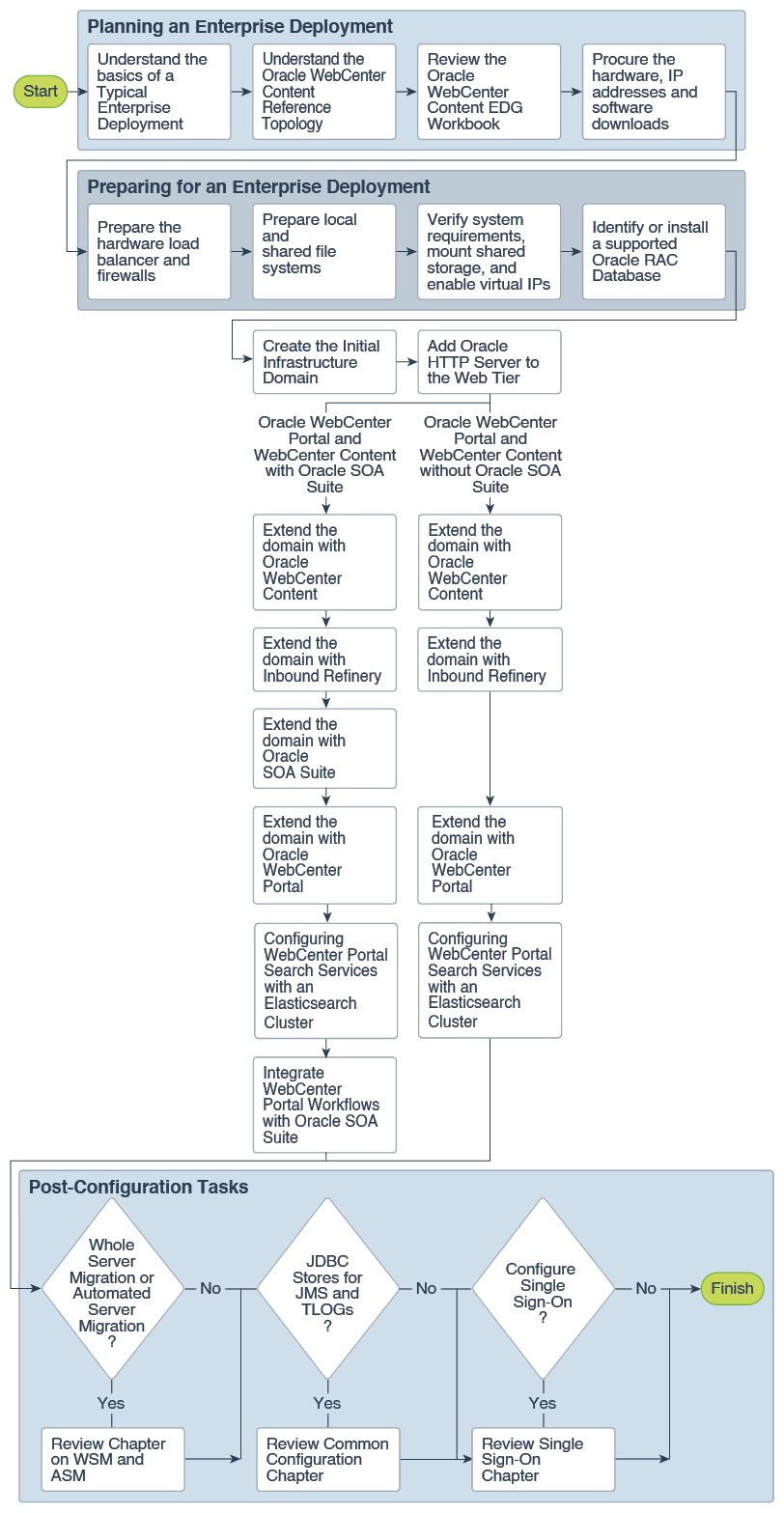
Flow Chart of the Steps to Install and Configure the WebCenter Portal Enterprise Topologies
The following flow chart shows the steps required to install and configure the primary enterprise deployment topologies described in this chapter. The sections following the flow chart explain each step in the flow chart.
This guide is designed so you can start with a working WebCenter Portal domain and then later extend the domain to add additional capabilities.
This modular approach to building the topology allows you to make strategic decisions, based on your hardware and software resources, as well as the Oracle WebCenter Portal features that are most important to your organization.
It also allows you to validate and troubleshoot each individual product or component as they are configured.
This does not imply that configuring multiple products in one Configuration Wizard session is not supported; it is possible to group various extensions like the ones presented in this guide in one Configuration Wizard execution. However, the instructions in this guide focus primarily on the modular approach to building an enterprise deployment.
Roadmap Table for Planning and Preparing for an Enterprise Deployment
The following table describes each of the planning and preparing steps shown in the enterprise topology flow chart.
| Flow Chart Step | More Information |
|---|---|
|
Understand the basics of a Typical Enterprise Deployment |
|
|
Understand the specific reference topology for the products that you plan to deploy |
Review the product-specific topologies and the description of the topologies, including the virtual servers required and the summary of clusters and Managed Servers recommended for the product-specific deployment. |
|
Review the Oracle WebCenter Portal EDG Workbook |
|
|
Procure the hardware, IP addresses, and software downloads |
|
|
Prepare the hardware load balancer and firewalls |
Preparing the Load Balancer and Firewalls for an Enterprise Deployment |
|
Prepare the file system |
|
|
Verify system requirements, mount shared storage, and enable virtual IPs |
|
|
Identify or install a supported Oracle RAC Database |
Roadmap Table for Configuring the Oracle WebCenter Portal Topology
Table 3-3 describes each of the configuration steps required when configuring the topology shown in Diagram of the WebCenter Portal Enterprise Deployment Topology.
These steps correspond to the steps shown in the flow chart in Flow Chart of the Steps to Install and Configure the WebCenter Portal Enterprise Topologies.
Table 3-3 Roadmap Table for Configuring the Oracle WebCenter Portal Topology
| Flow Chart Step | More Information |
|---|---|
|
Create the initial Infrastructure domain |
Creating the Initial Infrastructure Domain for an Enterprise Deployment |
|
Extend the domain to Include the Web Tier |
|
|
Extend the domain with Oracle WebCenter Content |
|
|
Extend the domain with Inbound Refinery |
|
|
Extend the domain with Oracle SOA Suite |
|
|
Extend the domain with Oracle WebCenter Portal |
|
|
Integrating WebCenter Portal with Oracle SOA Suite in the Same Domain |
Integrating WebCenter Portal Workflows with Oracle SOA Suite in the Same Domain |
