4 About Cartridge Modeling
This chapter describes how the Oracle Communications Network Integrity UIM Integration cartridge is modeled in Oracle Communications Design Studio.
UIM Integration Cartridge UML Representation
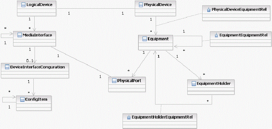
Figure 4-1 displays a Unified Modeling Language (UML) diagram depicting the object relationship being rendered.
Figure 4-1 UIM Integration Cartridge UML Representation

Description of "Figure 4-1 UIM Integration Cartridge UML Representation"
Oracle Communications Information Model Information
Oracle Communications Unified Inventory Management (UIM) does not support Device Interface Configuration and Media Interface entities. The Device Interface Configuration entity is excluded from integration. MediaInterface in Network Integrity is mapped to DeviceInterface in UIM.
The Media Interface entity may be realized as either DeviceInterface or MediaInterface in Network Integrity. It can be realized only as DeviceInterface in UIM.
Attributes that are defined in the Oracle Communications Information Model, supported by Network Integrity, but not supported by UIM are implemented as characteristics in UIM and are mapped from attribute to characteristic and from characteristic to attribute. These characteristics are not mandatory in UIM. If they are not present, the value is empty on import and is not set during resolution. All other attributes are mapped directly.
Device Hierarchy
The UIM Integration cartridge supports both logical device and physical device hierarchies. The cartridge supports physical-to-logical mapping relationships (physical-device-to-logical-device mapping and physical-port-to-device-interface mapping).The cartridge supports both Device Interface and Media Interface entities. In UIM, Media Interface is represented as Device Interface with additional characteristics.
Characteristics
Table 4-1 shows characteristics included in the ora_ni_uim_ocim cartridge.
Table 4-1 Characteristics in the ora_ni_uim_ocim Cartridge
| Characteristic | UI Label | Field Type | Notes |
|---|---|---|---|
|
nativeEmsName |
Native EMS Name |
Text |
N/A |
|
nativeEmsAdminServiceState |
Native EMS Admin Service State |
Text |
Available values:
|
|
nativeEmsServiceState |
Native EMS Service State |
Text |
Available values:
|
|
mtuCurrent |
MTU Current |
Text |
N/A |
|
mtuSupported |
MTU Supported |
Text |
N/A |
|
nativeEmsConnectorPresent |
Native EMS Connector Present |
Check box |
N/A |
Logical Mapping
The UIM Integration cartridge supports the following logical mappings.
Logical Device
Table 4-2 shows characteristics for the Logical Device specification.
Table 4-2 Logical Device Characteristics
| Characteristic | Information Model Support | Field Type |
|---|---|---|
|
nativeEmsName |
Static |
Text |
|
nativeEmsAdminServiceState |
Static |
Text |
|
nativeEmsServiceState |
Static |
Text |
|
physicalLocation |
Static |
Text |
Device Interface
Table 4-3 shows characteristics for the Device Interface specification.
Table 4-3 Device Interface Characteristics
| Characteristic | Information Model Support | Field Type |
|---|---|---|
|
nativeEmsName |
Static |
Text |
|
nativeEmsAdminServiceState |
Static |
Text |
|
nativeEmsServiceState |
Static |
Text |
|
physicalLocation |
Static |
Text |
|
ifType |
Static |
Text |
|
minSpeed |
Static |
Text |
|
maxSpeed |
Static |
Text |
|
nominalSpeed |
Static |
Text |
|
physicalAddress |
Static |
Text |
|
mtuCurrent |
Static |
Text |
|
mtuSupported |
Static |
Text |
|
nativeEmsConnectorPresent |
Static |
Check box |
Physical Mapping
The UIM Integration cartridge supports the following physical mappings.
Physical Device
Table 4-4 shows characteristics for the Physical Device specification.
Table 4-4 Physical Device Characteristics
| Characteristic | Information Model Support | Field Type |
|---|---|---|
|
nativeEmsName |
Static |
Text |
Equipment
Table 4-5 shows characteristics for the Equipment specification.
Table 4-5 Equipment Characteristics
| Characteristic | Information Model Support | Field Type |
|---|---|---|
|
nativeEmsName |
Static |
Text |
|
physicalLocation |
Static |
Text |
Equipment Holder
Table 4-6 shows characteristics for the Equipment Holder specification.
Table 4-6 Equipment Holder Characteristics
| Characteristic | Information Model Support | Field Type |
|---|---|---|
|
nativeEmsName |
Static |
Text |
|
physicalLocation |
Static |
Text |
Physical Port
Table 4-7 shows characteristics for the Physical Port specification.
Table 4-7 Physical Port Characteristics
| Characteristic | Information Model Support | Field Type |
|---|---|---|
|
nativeEmsName |
Static |
Text |
|
physicalLocation |
Static |
Text |
|
serialNumber |
Static |
Text |
|
physicalAddress |
Static |
Text |