3 Configuration Tab Operations
The Configuration tab on the Web GUI provides dialogs for the same configuration objects that you can access from the command line to configure the Oracle® Enterprise Session Border Controller (E-SBC). You may find the GUI easier to use than the command line.
- Basic mode—Displays a
limited set of configuration objects. Basic mode is used for quick prototyping
of an
E-SBC deployment for
proof of concept or testing purposes. It is not meant for production use. You
must switch to Expert mode to access the full array of configuration objects.
Note:
After switching to Expert Mode, you can only return to Basic mode if you have not saved and activated any changes that you made. After saving and activating, you must reinstall the software to enter Basic Mode again. - Expert mode—Displays the complete list of the configuration objects. When you click an object on the list, the Web GUI displays the corresponding configuration dialog.
- Wizards—Displays the
following list of Wizards that lead you through selected configuration tasks.
You can use the Wizards in Basic mode and Expert mode.

- Commands—Displays the
following list of show commands that provide a view of the state of
configuration on the
E-SBC.

- Configuration
objects—Displays a list of the configuration objects either by category, like
the ACLI, or in alphabetical order. Use the arrow control to expand each list
to see all of the configuration objects and sub-objects.

Configuration States and Behavior
After you finish creating or modifying a configuration, you must save and activate the configuration before the Oracle® Enterprise Session Border Controller (E-SBC) saves the changes to the running configuration.
- Editing. The editing configuration is the version that you are making changes to from the Web GUI. The editing version is stored in the E-SBC volatile memory. The editing version cannot survive a system reboot.
- Saved. The saved configuration is the version of the editing configuration that the system copies into the non-volatile memory when you click Save on the Web GUI. Until you activate the saved configuration, the changes do not take effect on the E-SBC. The system does not load the saved, but not activated, configuration as the running configuration on reboot.
- Running configuration. The running configuration is the configuration that the system is using. When you activate the saved configuration it becomes the running configuration. Most configuration changes can take effect upon activation. Some configuration changes require a system reboot. On reboot, the system loads the running configuration.
- OK. All configuration dialogs display an OK button that saves changes to the editing memory. If you reboot before the next step, the E-SBC does not save the changes.
- Save. The Save button on the Web GUI toolbar verifies the configuration, displays errors, saves the current configuration to the last-saved configuration, and stores it on the E-SBC. The system displays any errors at the bottom of the Configuration page.
- Activate. After you finish making one or more configuration changes, OK and Save from the last configuration dialog that you need to edit at this time. The system displays the Confirmation dialog containing the Activate button. When you click Activate, the E-SBC activates all of the saved configuration changes and saves the new configuration to the running configuration. If you cancel the activation function, the E-SBC saves the configuration in a file and does not change the running configuration. You can continue to make changes to the configuration.
Configuration Error Messages
If you save a configuration that contains errors, the system displays the following error message: There were errors! Are you sure you want to activate the configuration?
The system displays a list of errors at the bottom the page. Click an error to go to the location in the configuration where the error occurred and edit the configuration as needed.
| Severity | Identifies the level of severity that the Oracle
Enterprise Session Border Controller assigns to the error. Valid values are:
|
| Message | Identifies the element field where the error, warning, or critical error occurred, and the reason for the error. |
| Object | Identifies the element and the field for that element where the error occurred. |
| Attribute Name | Identifies the attribute within the element where the error occurred. |
| Other | Identifies any other pertinent information relating to the error. |
Configuration Wizards
The Wizards control in the navigation pane displays a list of Wizards, for performing selected configuration procedures for the Oracle® Enterprise Session Border Controller (E-SBC).
| Set Boot Parameters | Specify the boot file and the boot parameters. |
| Set Entitlements | Set the number of sessions that a license entitles you to, and enable advanced features. |
| Set Initial Configuration | Configure a new E-SBC or reconfigure an existing one. Includes configuring High Availability. |
| Set License | Enter the license number for a feature that requires a license. |
| Set Logon Banner | Customize the text on the Web GUI log on banner. |
| Set Time Zone | Select the time zone for the deployment. |
| Upgrade Software | Upload a newer version of the software. |
Set Boot Parameters Wizard
The Oracle® Enterprise Session Border Controller (E-SBC) requires you to enter the necessary parameters to boot the system in your deployment.
You can set the E-SBC boot parameters from the Set Boot Parameters Wizard on the Web GUI in either Basic mode or Expert mode.
Set Entitlements Wizard
Use the Set Entitlements Wizard to enter the maximum number of sessions that your license allows.
- Note the session limit number from your license.
You can launch the Set Entitlements Wizard on the Web GUI in either Basic mode or Expert mode.
Set Initial Configuration Wizard
Use the Set Initial Configuration wizard to perform the initial configuration on an unconfigured system and to change the configuration on a configured system. During the configuration, you select the scope of configuration that you want to perform, define the boot parameters, opt to set a VLAN, and configure features such as High Availability (HA) and access to the Oracle Communications Session Delivery Manager (OC SDM). A valid license is required to run the Set Initial Configuration wizard.
Launch the Set Initial Configuration Wizard
- Unconfigured system. The system launches the Web GUI Set Initial Configuration wizard upon the first logon. When the initial configuration is complete, the system saves the configuration, activates the configuration, and reboots. The system does not backup the initial configuration of an unconfigured system.
- Configured system. From the Configuration tab on the Web GUI, click the Wizards button and click Set Initial Configuration. When the re-configuration is complete, the system saves a backup of the existing configuration, saves the new configuration, activates the new configuration, and reboots. The backup is stored in /code/bkups.
| Enable Web GUI: Yes or No | If you select No, you may continue using the Wizard to set the initial configuration until you reboot. After you reboot, the system no longer displays the Web GUI. If you want to enable the Web GUI in the future, configure the Web Server Config object from the ACLI. |
| Choose Web GUI Mode: Basic or Expert | When selecting Basic mode or Expert mode, the
decision is about how much control you want in the configuration process and
whether or not you want to use one of more of the advanced features and
settings provided in Expert mode.
|
| E-SBC Mode: Standalone or High Availability |
|
| E-SBC Role: Primary or Secondary | If you selected High Availability for
E-SBC Mode:
|
Note:
Unlike other E-SBCs, which provide 2 management interfaces and 2 media interfaces, the Acme Packet 1100 provides 1 management interface and 2 media interfaces. When configuring HA, the configuration dialogs for the Acme Packet 1100 differ from the other E-SBCs because you must create a second, virtual management interface. For creating the second management interface, the HA dialogs on the Acme Packet 1100 contain more attributes than the dialogs for the other E-SBCs. Regardless of the E-SBC model, the path through the Set Initial Configuration wizard to the HA dialogs is the same as described in this topic.Configure the System
The system requires an initial configuration of attributes, such as modes and IP addresses, before it can function in the network.
Use the Set Initial Configuration Wizard to define the attributes for the system. The system displays the Set Initial Configuration Wizard upon the first logon.
- Configure the system objects.
Set License Wizard
Use the Set License Wizard to enter the serial number for your license. You can use the Set License Wizard in Basic Mode and Expert Mode.
- Obtain the license, which includes the serial number, for the feature that you want to add to the deployment. See "Obtain a License" in the ACLI Configuration Guide.
You need the license number for the following procedure.
Set Login Banner Wizard
Use the Set Login Banner Wizard to add customized text to the log on page. You can use the Set Login Banner Wizard in Basic mode and Expert Mode.
You can customize the log on page by adding text to help the user. For example, Welcome to <company name> <business unit> <location> session border controller <device name>.
Set Time Zone Wizard
The system requires a setting for time zone.
You can set the system time from the Set Time Zone Wizard on the Web GUI. You can select a time zone or Coordinated Universal Time (UTC). You can use the Set Time Zone Wizard in Basic Mode and Expert Mode.
Upgrade Software Wizard
You can upgrade the system software with the Upgrade Software Wizard on the Web GUI. You can use the Upgrade Software Wizard in Basic Mode and Expert Mode.
Use the Upgrade Software Wizard to perform the following tasks:
- Check the system health before the upgrade
- Download new software
- Change boot parameters
- Reboot the system
The system requires a reboot after the upgrade for the changes to take effect.
Configuration in Basic Mode
The Oracle® Enterprise Session Border Controller (E-SBC) Web GUI displays both a Basic Mode and an Expert Mode for configuring the system. Basic Mode provides a subset of the Expert Mode configuration objects, and is intended for use as a quicker way to configure the E-SBC for proof-of-concept and testing purposes. Basic Mode provides only the minimum number of configuration objects required to get the system up and processing calls. After you are satisfied with system operations, you can switch to Expert Mode and continue to specify a more robust and customized configuration. The E-SBC preserves the settings that you applied in Basic Mode and displays them in the corresponding dialogs in Expert Mode along with the additional settings available in Expert Mode. Using Basic Mode is optional. You can configure the E-SBC from start to finish in Expert Mode.
Note:
After you switch to Expert Mode, you can only switch back to Basic Mode if you have not saved and activated in Expert Mode.
Basic Mode configuration requires connecting the E-SBC to your network and setting the parameters for the operations that you want the E-SBC to perform. In Basic Mode, the Configuration tab displays a drop down list of possible devices that you can connect and a list of configuration objects. You can also group devices and establish one-way and two-way routes between each one and the E-SBC.
Connect to the Network
When you first click the Configuration tab in Basic Mode, the center pane displays the following list of "Devices" that you can connect to the E-SBC.

When you click a device, the GUI displays the corresponding configuration dialog. After you configure the device, click SIP Interface on the Devices list. The system prompts you specify whether you want the configured device on the Enterprise side or the Service Provider side of the E-SBC. When you complete the SIP Interface configuration, you can set one-way or two-way routes for traffic to and from the device to the E-SBC. You can also group devices.
Example 3-1 Set the Parameters
On the Configuration tab, the navigation panel lists all of the configuration objects that you need for the E-SBC in Basic Mode. Some objects, such as Set Entitlements, launch a configuration dialog directly because they are single-instance configurations. Such dialogs display a list of parameters that you can set. For example:

When you complete the configuration, the dialog closes and displays the landing page for the object.
Other configuration objects, such as TLS Profile, are multi-instance objects that launch a page that can display a list of the configured objects. Such objects display the Add button and a table for listing configurations. For example:

When you click Add on such a page, the Web GUI launches the configuration dialog. For example:

When you OK the configuration dialog, the system returns to the Configuration object list page and adds the new configuration to the list. For example:

Repeat the process to add more configurations to the list.
Basic Mode Configuration Controls
In Basic mode, the Configuration page displays the following controls that lead to the listed configuration dialogs.
Branding Bar
The branding bar displays the following controls:
| Save | Perform a verification and save the changes to the non-volatile memory. You must activate the changes before the system can apply them to the running configuration. If the configuration contains errors, the Web GUI displays them along with a dialog where you can confirm or cancel activating the changes. |
| Verify | Confirm that a configuration is valid before you save your changes. |
| Settings | Access the following
settings:
|
| Discard | Undo any changes that you made and revert to the previous configuration. |
| Switch to Expert | Change to the Expert
Mode to see more configuration objects than Basic Mode provides.
Note: After switching to Expert Mode, you can only return to Basic Mode if you have not saved and activated any changes that you made. After saving and activating in Expert Mode, you must reinstall the software to enter Basic Mode again. |
| Search | Use to find one or more configuration objects. For example, if you type "host," the GUI displays a list of every configuration object that contains "host." |
Navigation Pane
The Basic Mode navigation tree displays the configuration objects in the following groups.
| Wizards |
|
| Devices |
|
| Management |
|
| Network |
|
| Others |
|
| SBC |
|
| Security |
|
Edit, Copy, and Delete Configurations
You can edit, copy, and delete one or more multi-instance configurations on the Oracle® Enterprise Session Border Controller (E-SBC) by way of the controls that the Web GUI displays on the Configuration tab. The edit and copy functions act only on a single instance of a configuration. The delete function can act on either a single instance or all instances.
Note:
You cannot copy or delete single-instance configurations. You can only edit them.To edit, copy, or delete a single, multi-instance configuration, select the configuration and right-click. The Web GUI displays the Edit, Copy, and Delete menu.

- When you click Delete, the system displays a confirmation dialog before performing the operation.
- When you click either Copy or Edit, the GUI displays the corresponding configuration dialog.
Caution:
Delete All does not act on a partial selection of the configurations. For example, if you select two of three configurations and click Delete All, the system deletes all three.Settings Configuration
Use the Settings configuration to set the following parameters.
| SBC Host Name | Name the session border controller host. |
| Description | Describe the session border controller host. |
| Location | Specify the location of the session border controller host. |
| Default Gateway IP Address | Specify the gateway IP address for the host. |
| NTP IP Address | Specify the IP address of the Network Time Protocol server. |
| Enable Restart on Critical Failure | Enable automatic system restart after a critical failure. |
| Logging Settings | Specify the Syslog server and the process log level.
|
| SNMP Settings | Enable SNMP traps and specify the MIB system.
|
| SIP Settings | Configure SIP and add SIP options.
|
| Denial of Service Settings | Specify packet rate settings for Denial of Service
protection.
|
| Communications Monitoring Probe Settings | Enable the Communications Monitoring Probe and
specify the collector.
|
| High Availability Settings | Enable High Availability and specify the peers.
For the Acme Packet 1100, see "High Availability for the Acme Packet 1100." |
| Packet Capture Settings | Enable packet capture and specify the receiver.
|
| Survivability | Enable remote site survivability and specify the
triggering device.
|
Logging Settings
You can configure the Oracle® Enterprise Session Border Controller (E-SBC) to generate Syslogs for system management and Process logs for debugging.
The E-SBC generates the following types of logs.
- Syslogs conform to the standard used for logging servers and processes as defined in RFC 3164. In configuration, you specify the Syslog server.
- Process logs are proprietary Oracle logs that the system generates on a per-task basis and are used mainly for debugging purposes. Because process logs are more data inclusive than Syslogs, their contents usually include Syslog log data. In configuration, you specify the log level.
Syslog and process log servers are both identified by an IPv4 address and port pair.
Configure Logging Settings
The Oracle® Enterprise Session Border Controller (E-SBC) generates SysLogs and process logs. You must configure the IP address for the SysLog server and the process log level for the process logs.
- Note the IP address of the Syslog server.
- Confirm that the system displays the Basic mode.
The Web GUI displays the logging configuration parameters on the Settings page. Use the following procedure to specify the Syslog server and to select a process log level.
Simple Network Management Protocol
Simple Network Management Protocol (SNMP) supports the monitoring of devices attached to the network for conditions that might need administrative attention.
- SNMP Settings—Specifies the MIB contact information and enables event SNMP traps. See "Configure SNMP Settings."
- SNMP Community—Specifies how certain E-SBC events are reported. See "Configure SNMP Community."
- Trap Receiver—Specifies the trap receiver settings, including filters. See "Configure an SNMP Trap Receiver."
Configure SNMP Settings
Simple Network Management Protocol (SNMP) is used to support the monitoring of devices attached to the network, such as the Oracle® Enterprise Session Border Controller (E-SBC), for conditions that warrant administrative attention.
- Confirm that the system displays the Basic mode.
The Web GUI displays the SNMP settings configuration parameters on the Settings page. Use the following procedure to configure MIB settings and to enable SNMP for the E-SBC.
SIP Settings
Session Initiation Protocol (SIP) is an IETF-defined signaling protocol widely used for controlling communication sessions such as voice and video calls over Internet Protocol (IP). You can use the protocol for creating, modifying, and terminating two-party (unicast) or multiparty (multicast) sessions. Sessions may consist of one or several media streams.
Dialog Transparency
Dialog transparency prevents the Oracle® Enterprise Session Border Controller (E-SBC) from generating a unique Call-ID and modifying dialog tags. With dialog transparency enabled, the E-SBC cannot generate a unique Call-ID and from modifying the dialog tags. The E-SBC passes what it receives. When a call made on one E-SBC is transferred to another UA and crosses a second E-SBC, the second E-SBC does not note the context of the original dialog, and the original call identifiers are preserved end to end. The signaling presented to each endpoint remains in the appropriate context regardless of how many times a call crosses through a E-SBC or how many E-SBCs a call crosses.
Without dialog transparency enabled, the E-SBC SIP B2BUA rewrites the Call-ID header and inserted dialog cookies into the From and To tags of all messages it processes. These dialog cookies are in the following format: SDxxxxxNN-. Using these cookies, the E-SBC can recognize the direction of a dialog. However, this behavior makes call transfers problematic because the Call-ID of one E-SBC might not be properly decoded by another E-SBC. The result is asymmetric header manipulation and unsuccessful call transfers.
IPv6 Reassembly and Fragmentation Support
As it does for IPv4, the E-SBC supports reassembly and fragmentation for large signaling packets when you enable IPV6 on the system.
The E-SBC takes incoming fragments and stores them until it receives the first fragment containing a Layer 4 header. With that header information, the E-SBC performs a look-up so it can forward the packets to its application layer. Then the packets are re-assembled at the applications layer. Media fragments are not reassembled and are forwarded to the egress interface instead.
On the egress side, the E-SBC takes large signaling messages and encodes them into fragment datagrams before it transmits them.
Oracle recommends that you send large SIP INVITE messages over TCP. If you want to modify that behavior, you can use the SIP interface’s option parameter max-udplength=xx for each SIP interface where you expect to receive large INVITE packets.
Other than enabling IPv6 on your E-SBC, there is no configuration for IPv6 reassembly and fragmentation support. It is enabled automatically.
Denial of Service Protection
The Oracle® Enterprise Session Border Controller (E-SBC) Denial of Service (DoS) protection functionality protects soft switches and gateways with overload protection, dynamic and static access control, and trusted device classification and separation in layers 3-5.
DoS protection prevents the E-SBC host processor from being overwhelmed by a targeted DoS attack from the following:
- IP packets from an untrusted source, as defined by provisioned and dynamic ACLs
- IP packets for unsupported and disabled protocols
- Nonconforming and malformed packets to signaling ports
- Volume-based attack of valid and invalid call requests, signaling messages, and so on.
The Server Edition and VM Edition support of DoS protection differs from the Oracle Hardware Platforms Edition due to the absence of Oracle network interface hardware. Consequently, DoS protection is implemented in software and consumes CPU cycles when responding to attacks.
The Server Edition and VM Edition handle media packet fragments differently, processing them in the data path rather than in the host application code. Protection against fragment attacks occurs because the system never keeps fragments for more than 5 milliseconds.
Configure Denial of Service Settings
Configure Denial of Service (DoS) settings to protect the Oracle® Enterprise Session Border Controller (E-SBC) from signal and media overload, while allowing legitimate, trusted devices to continue receiving service during an attack.
- Plan the maximum number of packets per second that you want for trusted packets, un-trusted packets, and ARP packets.
- Confirm that the system displays the Basic mode.
The Web GUI displays the denial of service configuration parameters on the Settings page. Use the following procedure to specify the settings that the system uses to calculate the trusted, untrusted, and ARP packets per second. Note that the configured rate is specified in packets per second, but the system measures the rate in packets per millisecond. For example, when the configured rate is 3200 packets per second, the actual measured rate is 3 packets per millisecond.
Communication Monitoring Probe Settings
Palladion is the Oracle Communication Experience Manager.
The manager is powered by the Palladion Mediation Engine, a platform that collects SIP, DNS, ENUM, and protocol message traffic received from Palladion Probes. The mediation engine stores the traffic in an internal database, and analyzes aggregated data to provide comprehensive multi-level monitoring, troubleshooting, and interoperability information.
Palladion simplifies the operation of software-based Palladion probes by enabling the transmission of Internet Protocol Flow Information Export (IPFIX) data to one or more Palladion Mediation Engines, possibly on different sub-nets.
Note:
The Palladion Communications Monitor Probe communicates over the media interface for signaling and Quality of Service (QoS) statistics using IPFIX. QoS reporting is done by way of Call Detail Records (CDR) accounting.Configure Communication Monitoring Probe Settings
Use the following procedure to establish a connection between the Oracle® Enterprise Session Border Controller (E-SBC) and the Palladion Mediation Engine. The E-SBC exports protocol message traffic and data and the Palladion Mediation Engine collects the information.
- Confirm that the network interface that you want to monitor is configured.
- Confirm that the system displays the Basic mode.
The Web GUI displays the communication monitoring probe settings configuration parameters on the Settings page. Use the following procedure to enable ths function, and to specify the connection parameters.
High Availability Settings
You can deploy the Oracle® Enterprise Session Border Controller (E-SBC) in pairs to deliver High Availability (HA). Two E-SBCs operating in this way are called an HA node. Over the HA node, call state is shared, keeping sessions and calls from dropping in the event of a service disruption.
When two E-SBCs work together in an HA node, one operates in active mode and the other one operates in standby mode.
- The active E-SBC checks itself for internal process and IP connectivity issues. If it detects that it is experiencing certain faults, it hands over its role as the active system to the standby E-SBC.
- The standby E-SBC is the backup system, fully synchronized with the active E-SBC session status. The standby E-SBC monitors the status of the active system so that, if needed, it can assume the active role without the active system having to instruct it to do so. If the standby system takes over the active role, it notifies network management using an SNMP trap.
To produce seamless switch overs from one E-SBC to the other, the HA node uses shared virtual MAC and virtual IP addresses for the media interfaces in a way that is similar to Virtual Router Redundancy Protocol (VRRP). Sharing addresses eliminates the possibility that the MAC and IPv4 address set on one E-SBC in an HA node will be a single point of failure. The standbyE-SBC sends ARP requests using a utility IPv4 address and its hard-coded MAC addresses to obtain Layer 2 bindings.
When there is a switch over, the standby E-SBC issues gratuitous ARP messages using the virtual MAC address, establishing that MAC on another physical port within the Ethernet switch. To the upstream router, the MAC and IP are still alive, meaning that existing sessions continue uninterrupted.
In the HA node, the E-SBCs advertise their current state and health to one another in checkpointing messages so that each system is apprised of the other’s status. Using Oracle’s HA protocol, the E-SBCs communicate with UDP messages sent out and received on the interfaces carrying heartbeat traffic between the active and standby devices.
The standby E-SBC assumes the active role when:
- It has not received a checkpoint message from the active E-SBC for a certain period of time.
- It determines that the health score of the active E-SBC has decreased to an unacceptable level.
- The active E-SBC relinquishes the active role.
Configure High Availability
To create a High Availability (HA) pair of Oracle® Enterprise Session Border Controllers (E-SBC), you must configure one E-SBC as the active and the other E-SBC as the standby.
- Confirm that the system displays the Basic mode.
The Web GUI displays the HA configuration parameters on the Settings page. Use the following procedure to create an HA pair and to establish communication between the devices.
High Availability on the Acme Packet 1100
The Acme Packet 1100 supports High Availability (HA), but the configuration differs from other Oracle® Enterprise Session Border Controllers (E-SBC) because there is only one management interface on this device.
Unlike other E-SBCs, which provide two management interfaces and two media interfaces, the Acme Packet 1100 provides 1 management interface and 2 media interfaces. For HA, you must create a second management interface object on the Acme Packet 1100 with wancom0 for the name and VLAN for the sub-port-id. You can configure only one management interface in an HA pair with these settings and the system does not support more than one HA interface with a VLAN tag.
Note:
The Acme Packet 1100 E-SBC does not support High Availability (HA) for any call using the Time Division Multiplexing (TDM) interface.Configure the Active Acme Packet 1100 for HA
You can configure the Acme Packet 1100 primary for High Availability (HA) operations from the Web GUI by using the configuration tools in Basic mode.
- Confirm that the Oracle® Enterprise Session Border Controller software is installed on two separate systems.
You must perform the following procedure on the active system before configuring the standby system for HA operations.
Configure the secondary for High Availability. See "Configure the Acme Packet 1100 Secondary for High Availability (HA) - GUI Basic."
Configure the Standby Acme Packet 1100 for HA
You can configure the Acme Packet 1100 standby for High Availability (HA) operations from the Web GUI by using the configuration tools in Basic mode.
- Confirm that the Oracle® Enterprise Session Border Controller active is configured for HA operations.
When configuring the standby system, enter the same management interface VLAN that you entered for the primary system.
Packet Capture Settings
You can configure the packet capture function on the Oracle® Enterprise Session Border Controller (E-SBC) to view packet traffic on your network. For example, you might want to confirm the network configuration or to perform troubleshooting.
| Yes—Removes all existing files. | The system captures up to 25 new .pcap files. During the session, the system rotates the files in the /opt/traces directory by size. For example, the system keeps the last 25 files and rotates them when they reach 100 MB | |
| No—Keeps all existing files. |
|
Configure Packet Capture Settings
You can configure the Oracle® Enterprise Session Border Controller (E-SBC) to send packet captures to a designated receiver.
- Note the IP address and network interface of the device that you want the E-SBC to send captured packets.
- Confirm that the system displays the Basic mode.
Use the following procedure to enable the packet capture function and to specify where the E-SBC sends the captured packets.
Remote Site Survivability
The remote site survivability feature enables an Oracle® Enterprise Session Border Controller (E-SBC) that is deployed in a Remote Office/Branch Office (ROBO) site to detect the loss of communication over SIP-based telephony to the Enterprise’s core call processing Data Center.
When loss of communication is detected over the SIP service, the ROBO E-SBC dynamically switches into Survivable Mode, handling call processing locally and providing limited additional server functionality.
Note:
Remote Site Survivability supports SIP only. It does not support H.323 call signalling.Remote Site Survivability:
- Works with or without High Availability (HA).
- Is configurable in real-time, with no reboot required to enable this feature.
- Allows configuration by way of the E-SBC Web GUI.
- Maintains Historical Recording (HDR) statistics about being in survivability mode, such as:
- Whether or not the E-SBC is in survivable mode using the ACLI command, show health.
- Length of time the E-SBC was in survivable mode (records the number of times and the amount of time in survivability mode).
- Number of SIP messages handled in survivable mode.
- Number of SIP users registered locally in survivable mode (both existing based on cache, and separately - new registrations).
Configure Remote Site Survivability
You must enable remote site survivability on the Oracle® Enterprise Session Border Controller (E-SBC) and set the parameters before the system can enter and exit survival mode.
- Confirm that at least one session is configured.
The Web GUI displays the Survivability configuration parameters on the Settings page. Use the following procedure to enable remote site survivability, specify a triggering device, and optionally change the default settings.
Devices Configuration
Use Devices to access the following configuration objects.
| PBX | Configure a privately owned switching system for handling multiple telephone lines. See "Add a PBX." |
| Trunk | Configure IP communications through your PBX outside of your Enterprise network on an Internet connection. See "Add a Trunk." |
| Remote Workers | Configure a device set up outside your network, but connects to the Oracle® Enterprise Session Border Controller from a remote location. See "Add Remote Workers." |
| Device | Configure a network device in the Local Area Network. See "Add a Device." |
| Recording Server | Configure a third-party call recorder or the Oracle ISR Record and Store Server to record media transmitted during a communications session between multiple user agents. See "Add a Recording Server." |
| SIP Interface | Add a SIP network interface to the Enterprise side of the Oracle® Enterprise Session Border Controller. See "Add a SIP Interface." |
Add a PBX
You can perform the minimum configuration needed to connect a PBX to the Oracle® Enterprise Session Border Controller (E-SBC) from the Configuration tab in Basic mode.
- Configure inbound and outbound translation rules.
- Note any System Programming Language (SPL) options that you want to add.
- Confirm that the system displays the Basic mode.
- Configure the Trunk.
Add a Trunk
You can perform the minimum configuration needed to make connect a SIP Trunk to the Oracle® Enterprise Session Border Controller (E-SBC) from the Configuration tab in Basic mode.
- Configure inbound and outbound translation rules.
- Note any System Programming Language (SPL) options that you want to add.
- Confirm that the system displays the Basic mode.
- Configure optional network elements, such as Time Division Multiplexing (TDM), additional devices, a recording server, or remote workers.
- Configure routing policies.
Add a Remote Worker
A remote worker is a device that you set up outside of your network, which you connect to the Oracle® Enterprise Session Border ControllerE-SBC) from the remote location.
Add a SIP Device
- Configure inbound and outbound translation rules.
- Note any System Programming Language (SPL) options that you want to add.
- Confirm that the system displays the Basic mode.
- Configure the Trunk.
Add a Session Recording Server
A session recording server is either a third-party call recorder or the Record and Store Server on the Oracle® Enterprise Session Border Controller (E-SBC) for recording the media transmitted in session between multiple user agents.
Configure a SIP Interface
You can add up to five SIP interfaces to both the Enterprise side and the Service Provider side of your Oracle® Enterprise Session Border Controller (E-SBC). You can associate a SIP interface with any configured network interface.
- Create the TLS profile that you want to associate with each SIP interface that you configure.
- Create the SDES profile that you want to associate with each SIP interface that you configure.
- Configure the Session Recording Server that you want to associate with this each SIP interface that you configure.
Use the following procedure to configure a SIP interface for either the Enterprise side or the Service Provider side of the E-SBC. In the configuration process, you specify which side. Repeat the procedure for each additional SIP interface that you need.
The following list is a basic set of the available parameters. For the complete list of available parameters, see the ACLI Reference Guide. For more configuration instructions, see the ACLI Configuration Guide.
Management Configuration
Use the Management control to access the following configuration objects.
| Accounting | Specify call accounting strategy, protocol, receivers, servers, parameters, and options. See the Accounting Guide and the "RADIUS Authentication" and "TACACS+" sections of Getting Started" in the ACLI Configuration Guide. |
| SNMP Community | Add and specify one or more Simple Network Management Protocol (SNMP) communities. See "SNMP v1 v2 Community Configuration" in the ACLI Configuration Guide. |
| Trap Receiver | Add and specify one or more SNMP trap receivers. See the "SNMP Community and Trap Receiver Management" section of the "System Management" chapter in the Maintenance and Troubleshooting Guide, |
| Web Server | Specify the web server. See "Web Server TLS Configuration" in the ACLI Configuration Guide. |
Configure SNMP Community
Configure a Simple Network Management Protocol (SNMP) community to support the monitoring of devices, such as the Oracle® Enterprise Session Border Controller (E-SBC), attached to the network for conditions that warrant administrative attention.
- Confirm that SNMP is configured.
- Note the IP addresses that you want for this community.
Use this procedure to group network devices and management stations, and to set the access rights for the community.
Note:
Only devices that support SNMPv1 and SNMPv2c protocol can use SNMP community strings. SNMPv3 uses username and password authentication, along with an encryption key.Configure an SNMP Trap Receiver
You can define one or more SNMP trap receivers on an Oracle® Enterprise Session Border Controller (E-SBC) for redundancy or to segregate alarms with different severity levels to individual trap receivers.
- Confirm that SNMP is configured.
- Note the names of users who are allowed to receive secure traps.
Oracle recommends that you configure each server with an NMS installed as a trap receiver on each ESBC managed by an NMS. When configuring the trap-receiver element for use with Network Management Systems, Oracle recommends setting the filter-level parameter to All.
Web Server Configuration
The Web server is a software application that helps to deliver Web content that you can access through the Internet. The Web server runs the Enterprise application called the Web GUI.
Every Web server has an IP address and sometimes a domain name. For example, if you enter the URL http://www.acmepacket.com/index.html in your browser, the browser sends a request to the Web server with domain name is acmepacket.com. The server fetches the page named index.html and sends it to the browser.
If you enter http://132.45.6.5, and this address has been configured by your Administrator to access the Web GUI, the server fetches the page and displays the Web GUI logon page to your browser.
Network Configuration
Use the Network control to access the following configuration objects.
| Host Route | Specify where to direct management traffic. See the "Host Routes" section of the "System Configuration" chapter in the ACLI Configuration Guide. |
| Network Interface | Specify a logical network interface over which you can configure one or more SIP interfaces. See the "Network Interfaces" section of the "System Configuration" chapter in the ACLI Configuration Guide. |
Host Routes
Host routes let you insert entries into the Oracle® Enterprise Session Border Controller (E-SBC) routing table. These routes affect traffic that originates at the E-SBC host process. Host routes are used primarily for steering management traffic to the correct network.
When traffic is destined for a network that is not explicitly defined on an E-SBC, the default gateway is used. If you try to route traffic to a specific destination that is not accessible through the default gateway, you need to add a host route. Host routes can be thought of as a default gateway override.
Certain SIP configurations require that the default gateway is located on a front media interface. In this scenario, if management applications are located on a network connected to a rear-interface network, you need to add a host route for management connectivity.
When source-based routing is used, the default gateway must exist on a front media interface. Host routes might be needed to reach management applications connected to a wancom port in this kind of situation.
Network Interface Configuration
The Network Interface configuration object specifies a logical network interface. In order to use a network port on a network interface, you must configure both the physical interface and the corresponding network interface configuration elements.
Add a Network Interface
Use the Network Interface configuration object to create and configure a logical network interface.
You can add a network interface from the Web GUI in either Basic mode or Expert mode. If the network interface does not use VLANs tagging, ensure that the sub-port ID field is set to 0, the default value. When you set VLAN tags on a network interface, the valid sub-port ID value can range from 1-4096. The Network Interface object is a multiple instance configuration element. The combination of the name field and the sub-port ID field must be unique in order to identify a discrete network interface. Except where noted, you can use an IPv6 IP address in any parameter in the following procedure.
Others Configuration
Use the Other control to access the following multi-instance configuration objects.
| Media Profile | Use to add one or more media profiles. See the "Media Profiles Per Realm" and Multiple Media Profiles" sections of the "Realms and Nested Realms" chapter in the ACLI Configuration Guide. |
| SIP Features | Use to add one or more SIP features. See the "SIP Options" section of the "Realms and Nested Realms" chapter in the ACLI Configuration Guide. |
| SIP Manipulations | Use to add one or more rules for handling SIP headers. See "Configuring SIP Manipulations" in the ACLI Configuration Guide. |
| SPL | Use to add one or more SPL plug-ins. See the "Session Plug-In Language" chapter in the ACLI Configuration Guide. |
| Translation Rules | Use to add one or more translation rules. See the "Number Translation" chapter in the ACLI Configuration Guide. |
Configure Media Profile
You can configure one or more media profiles for the Oracle® Enterprise Session Border Controller to use as a rules for sending and receiving media over the network.
- One media profile for a particular SIP SDP encoding, such as G729, by providing a unique name to identify the profile for the particular encoding type.
- Multiple media profiles for the same SIP SDP encoding by adding a sub-name to the configuration. The system uses the sub-name plus the profile name as the unique identifier.
Configure Translation Rules
You can configure the Oracle® Enterprise Session Border Controller (E-SBC) to use number translation to change a layer 5 endpoint name according to prescribed rules. For example, to add or to remove a 1 or a + from a phone number sent from or addressed to a device. Use the translation-rules element to create unique sets of translation rules to apply to calling and called party numbers.
In the following procedure, you set the translation type, define the string to add or delete, and set the character position (index) where the add, delete, or replace occurs in the string. The index starts at 0, immediately before the leftmost character, and increases by 1 for every position to the right. Use the $ character to specify the last position in a string.
Configure SIP Features
Use the SIP Feature configuration object to define how the Oracle® Enterprise Session Border Controller (E-SBC) handles option tags in the SIP Supported header, Require header, and the Proxy Require header.
You can specify whether a SIP feature is applied to a specific realm or globally across all realms. You can also specify the treatment for an option based upon whether is appears in an inbound or outbound packet. You need to configure option tag handling in the SIP feature element only when you want a treatment other than the default.
SIP Manipulations
SIP header manipulation allows you to add, delete, or modify SIP message attributes on the Oracle® Enterprise Session Border Controller (E-SBC). For example, SIP headers and SIP header elements.
The most common reason for manipulating SIP headers and SIP header elements is to fix an incompatibility problem between two SIP endpoints. For example, Softswitch - PSTN incompatibility or a SIP messaging problem between two different IP PBX platforms in a multi-site deployment where calls between the platforms are unsuccessful due to problems in the SIP messaging.
To enable the SIP header manipulation, create rule sets in which you specify header manipulation rules and, optionally, header element manipulation rules. SIP header elements are the sub-parts of the header, such as the header value, the header parameter, the URI parameter, and so on, excluding the header name. You can specify the actions that you want the system to perform for each header element.
After creating the header manipulation rule set, apply it to a session agent or SIP interface as "inbound" or "outbound."
SIP Header Manipulation Configuration
Configuring SIP manipulations from the Web GUI is a multi-faceted process performed through a series of nested dialogs that differ depending on the particular header and header element that you want to manipulate. It is not practical to document the entire SIP manipulations configuration process in one procedure. The documentation begins with the "Configure SIP Manipulation", topic where you can set the global parameters, if that is all you need. The documentation continues with procedures for each particular header and header element that you can manipulate. Each of those topics includes the global settings, so you can set or modify them there, as well.
- Configure MIME Rule—includes the mime-header-rule element.
- Configure MIME ISUP Rule—includes the mime-header-rule and isup-param-rule elements.
- Configure MIME SDP Rule—includes the mime-header-rule, sdp-session-rule, and the sdp-media-rule.
When you finish configuring SIP manipulations, apply the rules to a session agent or SIP interface as "inbound" or "outbound."
SIP Manipulations Rules Attributes and Values Reference
Refer to the following table for information about the attributes that you can configure for SIP manipulation rules.
| Attributes | Values and Descriptions | ||||||||||||||||||||||||
|---|---|---|---|---|---|---|---|---|---|---|---|---|---|---|---|---|---|---|---|---|---|---|---|---|---|
| Action |
Default: None. |
||||||||||||||||||||||||
| Comparison type |
Default: Case-sensitive. |
||||||||||||||||||||||||
| Format |
|
||||||||||||||||||||||||
| Header name | The name of the header to which the rule applies. Case-sensitive. | ||||||||||||||||||||||||
| Match value | The value that you want to match against the element value for an action to be performed. | ||||||||||||||||||||||||
| Match val type | The type of value to match to the
match-field entry for the action to be performed.
|
||||||||||||||||||||||||
| Media type (SDP descriptor for SDP media rule) |
|
||||||||||||||||||||||||
| Methods | SIP method names to which you want to apply the header rule. For example, INVITE, ACK, BYE. When this field is empty, the system applies the MIME rule to all methods. Default: Blank. | ||||||||||||||||||||||||
| Mime header | The parameter name to which the rule applies. The parameter name depends on the element name you entered. For uri-param, uri-user-param, and header-param it is the parameter name to be added, replaced, or deleted. For all other types, it serves to identify the element rule and any name can be used. Alpha-numeric characters. Default: blank. | ||||||||||||||||||||||||
| Msg type |
Default: Any. |
||||||||||||||||||||||||
| Name | The name you want to use for the rule. Default: Blank. | ||||||||||||||||||||||||
| New value | The value for a new element or replacement
value for an existing element. You can enter an expression that includes a
combination of absolute values, pre-defined parameters, and operators.
The following table describes the pre-defined parameters.
The following table describes the Operators.
|
||||||||||||||||||||||||
| Parameter name | The parameter name to which the rule applies. The parameter name depends on the element name you entered. For uri-param, uri-user-param, and header-param it is the parameter name to be added, replaced, or deleted. For all other types, it serves to identify the element rule and any name can be used. Alpha-numeric characters. Default: Blank. | ||||||||||||||||||||||||
| Type | The type of element on which to perform the
action. Default: Blank.
|
||||||||||||||||||||||||
| Type (SDP descriptor for SDP line rule) |
|
Configure SIP Manipulation
When you need to modify specific components of a SIP message, configure a SIP manipulation rule. For example, you might need to resolve protocol differences between vendors. You can configure rules for SIP headers and for the sub-elements within the headers.
To begin, configure the Name, Description, (Optional) Split Headers, and (Optional) Join Headers attributes. When you reach the "Cfg Rules" section, click Add and select the header rule that you want to create. For further instructions, refer to the topics noted in the Cfg rules "Instructions" cell in the following table.
- Apply the rules to a session agent or SIP interface as "inbound" or "outbound."
Configure a SIP Manipulation Header Rule
You can configure SIP header rules and element rules on the Oracle® Enterprise Session Border Controller (E-SBC) from the "CfgRules" section of the "SIP Manipulations" page.
In the following procedure, you set the SIP Header Manipulation, Header Rule, and Element Rule parameters.
Configure a MIME Rule
You can configure Multi-Purpose Internet Mail Extensions (MIME) header rules and element rules on the Oracle® Enterprise Session Border Controller (E-SBC) from the "CfgRules" section of the "SIP Manipulations" page.
In the following procedure, you set the SIP Header Manipulation, MIME Rule, and MIME Header Rule parameters.
Configure a MIME ISUP Rule
You can configure Multi-Purpose Internet Mail Extensions (MIME) header rules and element rules on the Oracle® Enterprise Session Border Controller (E-SBC) from the "CfgRules" section of the "SIP Manipulations" page.
In the following procedure, you set the SIP Header Manipulation, MIME ISUP Rule, MIME Header Rule, and ISUP Param Rule parameters.
Configure a MIME SDP Rule
You can configure Multi-Purpose Internet Mail Extensions (MIME) header rules and element rules on the Oracle® Enterprise Session Border Controller (E-SBC) from the "CfgRules" section of the "SIP Manipulations" page.
In the following procedure, you set the SIP Header Manipulation, MIME SDP Rule, MIME Header Rule, SDP Session Rule, and SDP Media Rule parameters.
Add an SPL
Add an SPL plug-in, which is a customized script, to quickly implement a feature on the Oracle® Enterprise Session Border Controller (E-SBC). The SPL plug-in augments running the software image on the E-SBC, and provides new features when you need them without having to upgrade the software.
- Confirm the name and location of the SPL plug-in that you want to add.
Use the following procedure to integrate an Oracle-signed plug-in with the E-SBC operating system. Note that the E-SBC) does not load an unsigned SPL or one with invalid signatures.
SBC Configuration
Use the SBC control to access the following configuration objects. See the documentation specified in the following list for explanations of these configuration objects and how to set their parameters.
| Advanced Routing | See the "Session Routing and Load Balancing" chapter in the ACLI Configuration Guide. |
| Web Server | Enable and configure a web server, including a TLS profile. See the "Web Server TLS Configuration" chapter in the ACLI Configuration Guide. |
Security Configuration
Use the Security control to access the following configuration objects. See the documentation specified in the following list for explanations of these configuration objects and how to set their parameters.
| Certificate Record | Create a certificate record for either a CA or end entity. See "Online Certificate Status Protocol" in the ACLI Configuration Guide. |
| SDES Profile | Create a Session Description Protocol Security Descriptions (SDES) profile for media streams. See "Configure an SDES Profile" in the ACLI Configuration Guide. |
| TLS Profile | Create a profile to define communications security for running SIP over TLS See "Configure a TLS Profile" in the ACLI Configuration Guide. |
Expert Mode Configuration
Expert mode offers more configuration objects than Basic mode, which offers a limited set of configuration objects and is generally used only for proof of concept and testing purposes. Use Expert mode to see all of the features and settings available to help you fully customize the Oracle® Enterprise Session Border Controller (E-SBC) to your requirements.
The Expert mode configuration workspace displays a list of configuration objects and elements in the navigation pane. You can display them in either tree view (categorical) or list view (alphabetical) by way of Preferences from the User menu. When you click an object in navigation pane, the corresponding configuration dialog displays in the center pane.

Caution:
The Web GUI does not indicate required parameters or display an error message for those that contain no value. You may be able to save a configuration with a missing required value because the E-SBC ignores the parameter when it is not configured. The end result is a faulty configuration. Use the verify control that displays in every configuration dialog to validate the configuration.Expert Mode Configuration Controls
The Oracle® Enterprise Session Border Controller (E-SBC) Web GUI provides the following tools for working with configurations. Some tools are located in the navigation pane and others are located at the top of the center pane.
The Configuration Tab Display
The following screen capture shows the locations of all of the Configuration tab controls.
Controls in the Navigation Pane
The navigation pane displays links to Configuration Wizards and Show Commands. (Descriptions are listed in the center pane.) The Wizards help you specify certain parts of the configuration and the Commands show you information about the configuration of the system.

Controls in the Center Pane
The controls located at the top of the center pane on a configuration page help you manage configuration objects.

| Save | Use to save the current configuration session. Upon Save, the system displays a prompt giving you a choice of whether or not to activate the configuration. If you do not activate the configuration, you can continue to make changes and Save again. When finished, you can save and activate all of the configuration changes. |
| Verify | Use to confirm that the configuration is valid before you save it. |
| Discard | Use to undo all configuration changes made in the current session. The system can only discard the changes that you saved. It cannot discard any changes that you activated. |
| Search | Use to find and display the current settings for the configuration you are editing. Enter the name of the configuration object. |
Controls for Multi-Instance Objects
The controls located at the top of a list of multi-instance objects help you manage the objects on the list. The following screen capture shows the controls.

| Add | Use to add another instance of the configuration object with one or more parameters set differently. |
| Delete All | Use to delete all
instances.
Caution: You cannot select a sub-set of instances and delete only those. The system deletes all instances, regardless of how many you select. |
| Upload | Use to upload a configuration file in CSV format. |
| Download | Use to download a configuration file in CSV format. |
| Search | Use to search the list of multi-instances for a specific instance. When you enter the name of an instance, the Web GUI displays it at the top of the list. |
Using Tag Fields
The Oracle® Enterprise Session Border Controller provides a configuration element data field referred to as a tag. You enter information into the tag field for descriptive and grouping purposes. You can establish your own criteria for labeling configuration elements with these tags. Tag fields have no operational effect on signaling services.
The following configuration objects display the Tags text field:
- Agents
- Users
- Routes
You can enter any text that you want into the field and you can apply as many tags to a configuration object as needed. You can filter the element list searches using tags as a means of organizing these objects. Applicable element list search fields include a down arrow that exposes a tag drop-down list, from which you select the tag on which to filter the list. Tags have no operational function other than supporting this kind of filtering.
Edit, Copy, and Delete Configurations
You can edit, copy, and delete multi-instance configurations by way of the controls that the Web GUI displays on each multi-instance configuration page. The edit and copy functions act only on a single instance of a configuration. The delete function can act on either a single instance or all instances.
To edit, copy, or delete a single multi-instance configuration, select the configuration and right-click. The Web GUI displays the edit, copy and delete menu.
When you click Delete, the system displays a confirmation dialog before performing the operation. When you click either Copy or Edit, the GUI displays the configuration dialog.
Caution:
You cannot select several instances and delete only those. The system deletes them all, regardless of how many you select. For example, if you select two of three configurations and click Delete All, the system deletes all three.Media Manager Configuration
Use the Media Manager configuration object to define the settings for the media steering functions performed by the Oracle® Enterprise Session Border Controller (E-SBC), including timer limits, logging, and trust levels.
You can configure the following Media Manager objects from the Configuration tab on the Web GUI. See the documentation specified in the following list for explanations of these configuration objects and how to set their parameters.
| Codec Policy | Create a codec policy to specify allowed codecs, the order of codecs, and codecs to add on egress. See "Codec Policy Configuration" in the ACLI Configuration Guide. |
| DNS ALG Constraints | Configure and enable DNS ALG constraints. See the "DNS ALG Service Name Configuration" section of the "Application Gateway Services" chapter in the ACLI Configuration Guide. |
| DNS Config | Configure the DNS ALG service. See "DNS Configuration" in the ACLI Configuration Guide. |
| ICE Profile | Configure ICE profile. See "Configure ICE Profile" in the ACLI Configuration Guide. |
| Media Manager | Configure media steering functions. See "Creating Steering Pools for Multiple Interface Realms" in the ACLI Configuration Guide. |
| Media Policy | Configure a media policy and ToS settings. See "Packet Marking Configuration" in the ACLI Configuration Guide. |
| MSRP Config | Configure and enable MSRP. See "RCS Services" in the ACLI Configuration Guide. |
| Playback Config | Configure media use for playback. See "Local Media Playback" in the ACLI Configuration Guide. |
| Realm Config | Configure a realm for media management. See "Realms and Nested Realms" in the ACLI Configuration Guide. |
| Realm Group | Configure realm groups for local media playback. See "Configuring Realm Groups" in the ACLI Configuration Guide. |
| RTCP Policy | Configure an RTCP policy. See "Configuring RTCP Generation" in the ACLI Configuration Guide. |
| Static Flow | Configure static network traffic flows. See "Static Flows" in the ACLI Configuration Guide. |
| Steering Pool | Specify one or more ports for steering media flows. See "Steering Pools" in the ACLI Configuration Guide. |
| TCP Media Profile | Configure the TCP media profile and profile entries. See "Configure TCP Media Profile" in the ACLI Configuration Guide. |
Codec Policy Configuration
Codec policies describe how to manipulate SDP messages as they cross the Oracle® Enterprise Session Border Controller (E-SBC). The E-SBC bases its decision to transcode a call on codec policy configuration and the SDP. Each codec policy specifies a set of rules to be used for determining which codecs are retained or removed, and how they are ordered within SDP.
When configuring transcoding, you create a codec policy and associate the policy to a realm. In the codec policy, you specify:
- Which codecs to allow and which codecs to deny within a realm.
- Which codecs to add to the SDP m= lines for an egress realm.
- The preferred order of codecs shown in an SDP m= line.
- The packetization time to enforce within a realm for transrating.
Add a Codec Policy
You can create policies to specify how the Oracle® Enterprise Session Border Controller (E-SBC) manipulates SDP offers before passing the INVITE to the end point. For example, you might want to strip or re-order codecs when the originating device sends a particular codec that the end point does not support or prefer. Or, you might want to add codecs for transcoding. To simplify SIP end point management, the E-SBC can apply global codec policy enforcement to all end points.
Use the codec-policy configuration element to specify how the E-SBC handles codecs, and which codecs you want to allow.
Configure DNS ALG Constraints
You can limit throughput bound for DNS ALG by using the DNS ALG Constraints configuration element. The system performs message throttling on request messages, and the responses are automatically throttled because DNS-ALG is transaction stateful. The system displays a list of configured DNS ALG Constraints in the DNS Config dialog, which allows you to create constraint profiles and apply them to multiple DNS configuration objects.
This procedure requires you to enter rate and time constraints, which you might want to determine in advance. Note that 0 (zero) means unlimited.
- Apply the constraint to a DNS configuration.
Configure DNS
Use the DNS Config element to configure the DNS ALG service.
- Configure a DNS ALG constraint, if you want to apply one to this DNS configuration.
- Configure a server realm, if you want to add server DNS attributes.
Configure DNS for Application Gateway Service (ALG) per client, per realm.
Configure ICE Profile
Interactive Connectivity Establishment - Session Traversal Utility for NAT (ICE STUN lite mode) enables a Advanced Media Termination client to perform connectivity checks, and can provide several STUN servers to the browser. ICE STUN support requires configuring an ICE Profile under Realm Config, where you define the STUN behavior.
- Confirm that the realm to which you want to apply this profile exists.
- Set the ICE Profile parameter in Realm Config. See "Configure Advanced Media Termination in realm-config."
Configure Media Manager
Use the Media Manager element to define parameters used in the media steering functions performed by the Oracle® Enterprise Session Border Controller, including the flow timers.
Generate an RTCP Receiver Report
When you want to generate a Real-Time Transport Control Protocol (RTCP) Receiver Report separately from the default Sender-Receiver Report (RFC 3550), for example to encapsulate the receiver statistics differently, add the
xcode-gratuitous-rtcp-report-generation option in the media-manager configuration. After you add the option and reboot the system, the
E-SBC runs RTCP Receiver Reports for all media sessions that generate RTCP from DSPs.
When you add the
xcode-gratuitous-rtcp-report-generation option, be sure to type the
+ character before the option. The
+ character appends the new option to the realm configuration's options list. Without the + character, the system overwrites any previously configured options.
Configure Media Policy
Use the Media Policy element to configure the Type of Service (TOS) and Differentiated Services (DiffServ) values that define a type or class of service. Apply the media policy to one or more realms.
In the following procedure, you can enter any of the media types defined by the Internet Assigned Numbers Authority (IANA). For example, audio, example, image, message, model, multi-part, text, and video. You can enter any of the sub-media types defined by the IANA for a specific media type. For example, for the Image media type, you can use the sub-type jpeg. (image/jpeg)
Configure a Realm
Use the Realm Config element to configure a realm for the Oracle® Enterprise Session Border Controller (E-SBC).
- Configure a physical interface.
- Configure a network interface.
- If you use Quality of Service (QoS), confirm that QoS is enabled on the E-SBC.
Note:
In Advanced mode, in a table that contains the Realm ID column, you can click a cell in the column to view the realm configuration.Configure a Steering Pool
Use the steering-pool element to define sets of ports used to steer media flows through the Oracle® Enterprise Session Border Controller to provide packet steering to ensure a level of quality or a routing path.
- Configure and name the network interface to which you want to steer media.
In the following procedure, the combination of IP address, start port, and realm ID, must be unique.
Configure TCP Media Profile
The TCP Media Profile defines media operations in a realm. You can create multiple TCP Media Profiles, for example, to assign to different realms.
Advanced Media Termination Support
The Oracle® Enterprise Session Border Controller (E-SBC) supports VoIP calls through the browser-based, real-time communication known as Advanced Media Termination. Using W3C and IETF standards, Advanced Media Termination supports cross-browser video calls and data transfers, such as browser-based VoIP telephony and video streaming. Advanced Media Termination allows users to make and receive calls from within a web browser, relieving the need to install a soft phone application. With Advanced Media Termination, the E-SBC can enable users to communicate concurrently with one or more peers through various browsers and devices to stream voice and data communications in real-time through a variety of web applications. Advanced Media Termination also supports communications through end-user clients such as mobile phones and SIP User Agents.
- connected to networks with different throughput capabilities.
- on variable media quality networks (wireless).
- on fire-walled networks that don't allow UDP.
- on networks with NAT or IPv4 translation devices using any type of mapping and filtering behaviors (RFC 4787).
Supported Advanced Media Termination Services
- ICE-STUN (Lite mode) - Interactive Connectivity Establishment - Session Traversal Utility for NAT (ICE-STUN) enables an Advanced Media Termination client to perform connectivity checks. Use ICE to provide several STUN servers to the browser by way of the application. ICE processing chooses which candidate to address. Other benefits include support for IPv4, load balancing, and redundancy. ICE STUN support requires configuring an ICE Profile and specifying the profile in Realm Config. See "Configure ICE Profile" and "Configure Advanced Media Termination in Realm Config."
- RTP-RTCP multiplexing - Enables Real-Time Protocol (RTP) and Real-Time Control Protocol (RTCP) packets to use the same media port numbers. RTP is used for real-time multimedia applications, such as internet audio and video streaming, VoIP, and video conferencing. RTCP is used to monitor data transmission statistics and QoS, and helps to synchronize multiple streams. RTP-RTCP support requires enabling RTCP Mux in Realm Config. See "Configure Advanced Media Termination in Realm Config."
- DTLS-SRTP - Datagram Transport Layer Security (DTLS) provides integrated key and association management for secure data transfer for point-to-point media sessions. DTLS is especially optimized for use with Secure Real Time Protocol (SRTP), where it enables a Advanced Media Termination client to establish keys for SRTP and Secure Real Time Control Protocol (SRTCP). DTLS-SRTP support requires configuring a DTLS SRTP Profile under Media Security, and specifying the profile in the Realm Config. See "Configure DTLS SRTP Profile" and "Configure Advanced Media Termination in realm-config."
- SIP services including codec renegotiation, late media, early media, PACK interworking, attended and unattended call transfer, call forking, music on hold, transcoding, and High Availability.
Supported Protocols
- IPv4 for signaling and media
- UDP-RTP and UDP-RTCP on media
Supported Codecs
- Silk, OPUS, G.729, and G.711
Advanced Media Termination Configuration Process
To configure Advanced Media Termination for theOracle® Enterprise Session Border Controller, access the Security and Media Manager configuration objects to create the necessary profiles and associations. For RTCP Multiplexing support, you need only to enable it in the target realm. Advanced Media Termination is configurable in real-time. The system does not require a reboot.
- Confirm that the realm you want to configure for Advanced Media Termination exists.
- Confirm that the TLS profile that you want to specify in the DTLS SRTP Profile exists.
- In Security: Configure DTLS SRTP Profile, where you define the key exchange and DTLS handshake, the role the SBC negotiates when offered alternatives, and the crypto suites to use. See "Configure DTLS SRTP Profile."
- In Media Manger:
- Configure ICE Profile, where you define STUN behavior. See "Configure ice-profile."
- Configure Realm Config, where you specify the DTLS SRTP Profile, the ICE Profile, and enable RTCp Mux. See "Configure Advanced Media Termination in Realm Config."
Configure DTLS SRTP Profile
To provide Datagram Transport Layer Security-Secure Real Time Control Protocol (DTLS-SRTP) Advanced Media Termination services on the SBC, you must create a DTLS SRTP Profile. This profile defines the key exchange and DTLS handshake on a media session, the role the SBC negotiates when offered alternatives, and the crypto suites to use. After you create this profile, enter its name in the DTLS SRTP Profile parameter in the Realm Config.
- Specify this DTLS SRTP Profile in the Realm Config.
Configure ICE Profile
Interactive Connectivity Establishment - Session Traversal Utility for NAT (ICE STUN lite mode) enables a Advanced Media Termination client to perform connectivity checks, and can provide several STUN servers to the browser. ICE STUN support requires configuring an ICE Profile under Realm Config, where you define the STUN behavior.
- Confirm that the realm to which you want to apply this profile exists.
- Set the ICE Profile parameter in Realm Config. See "Configure Advanced Media Termination in realm-config."
Configure Advanced Media Termination in Realm Config
To support Advanced Media Termination functionality, the Oracle® Enterprise Session Border Controller (E-SBC) requires setting the parameters for RTCP Mux, DTLS SRTP Profile, and ICE Profile in Realm Config.
- Confirm that the realm exists that you want to configure for Advanced Media Termination operations.
- Confirm that the DTLS SRTP Profile and the ICE Profile exist.
Advanced Media Termination Troubleshooting
The Oracle® Enterprise Session Border Controller (E-SBC) provides Session Traversal Utility for NAT (STUN) and Datagram Transport Layer Security (DTLS) tracing.
To set STUN and DTLS tracing, go to Media Manager, Media Manager and set Options to "stun-trace dtls-trace". The E-SBC stores the STUN and DTLS traces in the Advanced Media Termination.log file.
Debug logs: log.sipd, log.mbcd, sipmsg.log, Advanced Media Termination.log
Security Configuration
The Oracle® Enterprise Session Border Controller (E-SBC) can provide security for VoIP and other multi-media services. E-SBC security includes access control, DoS attack, and overload protection to help secure service and protect the network infrastructure. E-SBC security lets legitimate users place a call during attack conditions, while protecting the service itself.
E-SBC security includes the numerous features and architecture designs of the Net-SAFE framework. Net-SAFE is a requirements framework for the components required to provide protection for the E-SBC, the service provider's infrastructure equipment (proxies, gateways, call agents, application servers, and so on), and the service itself.
| Audit Logging | Configure the size, location, and conditions that trigger the transfer of logs to the specified location. See "Configure the Audit Log" in the "Audit Log" chapter in the Administrative Security Guide. |
| Auth Params | Configure authentication protocol, strategy, and servers. See the "Authentication and Authorization" section in the "Access" chapter in the Administrative Security Guide. |
| Authentication | Configure RADIUS and TACACS authentication. See "RADIUS Authentication" and "TACACS+" in the ACLI Configuration Guide. |
| Certificate Record | Create a certificate record for either a CA or end entity. See "Certificate Configuration Process" in the ACLI Configuration Guide. |
| IKE Accounting Param | See the "IKEv2 Global Configuration" and "Configuring IKEv2 Interfaces" chapters in the Administrative Security Guide. |
| DTLS SRTP Profile | Configure the key exchange and DTLS handshake on a media session, the role the SBC negotiates when offered alternatives, and the crypto suites to use. See the "Configure DTLS SRTP Profile" section in the "Advanced Media Termination Support" chapter of the ACLI Configuration Guide. |
| Password Policy | Create a password policy. See the "Password Policy" section in the "Access" chapter in the Administrative Security Guide. |
| Public Key | Set the public key type and size. See the Administrative Security Guide. |
| Security Config | Configure security for VoIP and other multi-media services. See the "Security" chapter in the ACLI Configuration Guide. |
| SSH Config | Configure the system for an SSH connection. See "SSH Remote Connections" in the ACLI Configuration Guide. |
| TLS Global | Configure session caching to allow a previously authenticated client to re-connect with the unique session identifier from the previous session. |
| TLS Profile | Create a profile to define communications security for running SIP over TLS. See "Configure a TLS Profile" in the ACLI Configuration Guide. |
Audit Logs
The Oracle® Enterprise Session Border Controller (E-SBC) can record user actions in audit logs by way of the Web GUI. The audit logs record the creation, modification, and deletion of all user-accessible configuration elements, as well as attempted access to critical security data such as public keys. For each logged event, the system provides the associated user-id, date, time, event type, and success or failure data.
You can configure the system to record audit log information in either verbose mode or brief mode. Verbose mode captures the system configuration after every change, and displays both the previous settings and the new settings in addition to the event details. Brief mode displays only the event details. Although you can specify the recording mode, you cannot specify which actions the system records. The following list describes the actions that the system records.
| Global |
|
| Home tab |
|
| Configuration tab |
|
| System tab |
|
| Monitoring tab |
|
The system writes audit log events in Comma Separated Values (CSV) lists in the following format:
{TimeStamp,
src-user@address:port,Category,EventType,Result,Resource,Prev,
Detail}
The following list describes each value written to an audit log event.
| TimeStamp | Shows the time when the system wrote the event to the audit log. |
| src-user@address:port | Identifies the system that wrote the audit log line. |
| Category | Classifies the event as:
|
| EventType | Identifies the action that caused the event as:
|
| Result | Identifies the outcome of the event as:
|
| Resource | Describes the action within the event. Some of the
numerous actions that the system can log include:
|
| Prev—(verbose mode) | Displays the setting prior to this change. |
| Details—(verbose mode) | Displays additional information about the change,
depending on the following event types:
|
As the E-SBC records audit log data, users with admin privileges can read, copy, and download that information from the Web GUI. No one can delete or edit the original log. You can View, Refresh, and Download audit logs by way of the System tab. Go to Audit Log under File Management.
- The specified amount of time since the last transfer elapsed.
- The size of the audit log reached the specified threshold. (Measured in Megabytes)
- The size of the audit log reached the specified percentage of the allocated storage space.
The E-SBC transfers the audit logs to a designated directory on the target SFTP server. The audit log file is stored on the target SFTP server with a filename in the following format: audit<timestamp>. The timestamp is a 12-digit string the YYYYMMDDHHMM format.
- Configure secure FTP push. See "Secure FTP Push Configuration."
- Configure audit logging. See "Configure Audit Logging."
Secure FTP Push Configuration
You can configure the Oracle® Enterprise Session Border Controller (E-SBC) to securely send audit log files to an SFTP push receiver for storage. Configure secure FTP push before you configure audit logging.
It is also common for the SFTP server to run the Linux operating system. For Linux, the command ssh-keygen-e creates the public key that you need to import to the E-SBC. The ssh-keygen-e command sequence requires you to specify the file export type, as follows.
[linux-vpn-1 ~]# ssh-keygen -e
Enter file in which the key is (/root/.ssh/id_rsa/): /etc/ssh/ssh_host_rsa_key.pub
If you cannot access the SFTP server directly, but you can access it from another Linux host, use the ssh-keyscan command to get the key. An example command line follows.
root@server:~$ssh-keyscan -t dsa sftp.server.comConfigure Secure FTP Push with Public Key Authentication
For increased security when sending files from the Oracle® Enterprise Session Border Controller (E-SBC) to an SFTP server, you can choose authentication by public key exchange rather than by password. To use a public key exchange, you must configure public key profiles on both devices and import the key from each device into the other.
The following list of tasks shows the process for configuring authentication by public key between the E-SBC and an SFTP server. For each step in the process, see the corresponding topic for detailed instructions.
- Generate an RSA public key on the E-SBC. See "Generate an RSA Public Key."
- Create a DSA public key on the SFTP server. See "Generate a DSA Public Key."
- Import the DSA public key from the SFTP server into the E-SBC using the known-host option in the Import Key dialog. See "Import a DSA Public Key."
- Add the RSA public key to the authorized_keys file in the .ssh directory on the SFTP server. See "Copy the RSA Public Key to the SFTP Server."
Generate an RSA Public Key
Add a public key profile on the Oracle® Enterprise Session Border Controller (E-SBC) and generate an RSA key. You will later import the RSA key into the SFTP server to enable authentication by way of public key exchange with the E-SBC.
- Generate a DSA public key.
Generate a DSA Public Key
Generate and save a DSA public key on the SFTP server. You will later import the DSA key into the Oracle® Enterprise Session Border Controller (E-SBC) to enable authentication by way of public key exchange with the SFTP server.
- Run the following command on the SFTP server:
ssh-keygen -e -f /etc/ssh/ssh_host_dsa_key.pub | tee sftp_host_dsa_key.pub
- Save the key to the authorized_keys file in the .ssh directory on the SFTP server.
- Import the DSA key into the E-SBC.
Import a DSA Public Key
Import a DSA public key from the SFTP server into the Oracle® Enterprise Session Border Controller (E-SBC).
- Generate and save a DSA public key on the SFTP server.
Perform the following procedure on the E-SBC and select "known-host" for type.
Copy the RSA public key to the SFTP server.
Copy the RSA Public Key to the SFTP Server
Copy the RSA public key from the from the Oracle® Enterprise Session Border Controller (E-SBC) to the authorized_keys file in the .ssh directory on the SFTP server.
- Confirm that the .ssh directory exists on the SFTP server.
- Confirm the following permissions: Chmod 700 for .ssh and Chmod 600 for authorized_keys.
When adding the RSA key to the authorized_keys file, ensure that no spaces occur inside the key. Insert one space between the ssh-rsa prefix and the key. Insert one space between the key and the suffix. For example, ssh-rsa <key> root@1.1.1.1.
- Access the SSH file system on a configured SFTP server with a terminal emulation program.
- Copy the RSA key to the SFTP server, using a text editor such as vi or emacs, and paste the RSA key to the end of the authorized_keys file.
Configure Audit Logging
The Oracle® Enterprise Session Border Controller (E-SBC) provides a means of tracking user actions through Audit Logs. You can specify how the system records audit log information, and where to send the logs for archiving. You can configure the system to record in either brief or verbose mode. Verbose mode captures the system configuration after every change, and displays both the previous and new settings in addition to the event details. Brief mode displays only the event details.
- Configure one or more push receivers to receive the audit logs. See the documentation for the receiver.
- If you want to use public keys for authentication between the E-SBC and the push receiver, configure public key profiles on both devices before configuring audit logging. See "Configure Secure File Transfer with Public Keys."
Configure Login Timeouts
The single instance SSH Config configuration element specifies SSH re-keying thresholds.
TACACS+ Authentication
The Web GUI supports TACACS+ authentication.
TACACS+ provides access control for routers, network access servers, and other networked computing devices by way of one or more centralized servers. The Oracle® Enterprise Session Border Controller (E-SBC), supports TACACS+ authentication and limited accounting services. For accounting services support, the E-SBC supports only authentication success and failure. The E-SBC does not support TACACS+ authentication.
Security Settings
Security configuration from the web GUI consists of creating the building blocks used to establish TLS-secured paths for signaling traffic.
- Configure Certificate Records.
- Configure TLS Profiles, which utilize your certificate records.
- Apply TLS Profiles to SIP Interfaces.
The Certificate Records and TLS Profile configurations are located under Security on the Configuration page. Apply TLS profiles to SIP interfaces in the SIP Interface configuration under Session Router.
Certificate Configuration Process
You can perform the following certificate management tasks from the Web GUI in either Basic Mode or Advanced Mode. The process for configuring certificates on the Oracle® Enterprise Session Border Controller (E-SBC) includes the following steps:
- Configure a Certificate Record on the E-SBC. See Add a Certificate Record.
- Generate a Certificate request by the E-SBC. See Generate a Certificate Request.
- Import a Certificate into the E-SBC. See Import a Certificate.
- Reboot the system.
Create a Certificate Record
Use the certificate-record element to add certificate records to the Oracle® Enterprise Session Border Controller (E-SBC).
- If this certificate record is used to present an end-entity certificate, associate a private key with this certificate record by using a certificate request.
- If this certificate record is created to hold a CA certificate or certificate in pkcs12 format, a private key is not required.
- Create TLS profiles, using the certificate records to further define the encryption behavior and to provide an entity that you can apply to a SIP interface.
Generate a Certificate Request
Use the Certificate Record configuration object to select a certificate record and generate a certificate request.
- Confirm that the certificate record exists.
To get a certificate authorized by a Certificate Authority (CA), you must generate a certificate request from the certificate record on the device and send it to the CA.
- When the CA replies with the certificate, import the certificate to the device with the corresponding certificate record.
Import a Certificate
Use the Certificate Record configuration object to import a certificate into the Oracle® Enterprise Session Border Controller (E-SBC).
Use this procedure to import either a device certificate or an end-station CA certificate for a mutual authentication deployment. You must import the certificate to the corresponding certificate record for the E-SBC. End-station CA certificates may or may not need to be imported against a pre-configured certificate record.
- Apply the corresponding certificate record to the intended SIP interface.
SDES Configuration for a Media Stream
- Create at least one SDES profile that specifies the parameter values to negotiate during the offer-answer exchange.
- Create at least one Media Security Policy that specifies the key exchange protocols and protocol specific profiles.
- Assign the appropriate Media Security Policy to the appropriate realm.
- Create an interface-specific security policy that enables the E-SBC to identify inbound and outbound media streams treated as SRTP and SRTCP.
Configure an SDES Profile
A Session Description Protocol Security Descriptions (SDES) profile specifies the parameter values offered or accepted during SDES negotiation.
In the following procedure, use the Key and Salt parameters to generate the synchronous key used to encrypt and decrypt SRTP/SRTCP traffic originated by theOracle® Enterprise Session Border Controller (E-SBC). The E-SBC passes these concatenated values to the remote SRTP peer. Upon reception, the remote peer inputs the key and salt values to the negotiated encryption algorithm (AES in the current implementation), and derives the key required to decrypt SRTP/SRTCP traffic received from the E-SBC. The key parameter provides the basic keying material, while the salt (a bit string) provides the randomsess/entropy required by the encryption algorithm.
Configure DTLS SRTP Profile
To provide Datagram Transport Layer Security-Secure Real Time Control Protocol (DTLS-SRTP) Advanced Media Termination services on the SBC, you must create a DTLS SRTP Profile. This profile defines the key exchange and DTLS handshake on a media session, the role the SBC negotiates when offered alternatives, and the crypto suites to use. After you create this profile, enter its name in the DTLS SRTP Profile parameter in the Realm Config.
- Specify this DTLS SRTP Profile in the Realm Config.
TLS Profile Configuration
The Transport Layer Security (TLS) profile specifies the information required to run SIP over TLS.
TLS is a cryptographic protocol that provides communication security over the Internet. TLS encrypts the segments of network connections at the Application layer for the Transport layer, using asymmetric cryptography for key exchange, symmetric encryption for confidentiality and message authentication codes for message integrity.
Create a TLS profile, using your certificate records, to further define the encryption behavior and create the configuration element that you apply to the SIP interface. You can configure an end entity certificate and a trusted Certification Authority (CA) certificate for a TLS policy. CA certificates are issued by a CA to itself or to a second CA for the purpose of creating a defined relationship between the two entities. A certificate that is issued by a CA to itself is referred to as a trusted root certificate, because it is intended to establish a point of ultimate trust for a CA hierarchy. Once the trusted root has been established, it can be used to authorize subordinate CAs to issue certificates on its behalf.
Suite B and Cipher List Support
The Oracle® Enterprise Session Border Controller (E-SBC) supports full control of selecting the ciphers that you want to use for Transport Layer Security (TLS). The system defaults to DEFAULT for the Cipher List parameter in the TLS Profile configuration. Oracle recommends that you delete ALL and add only the particular ciphers that you want, choosing the most secure ciphers for your deployment.
- Key Algor—Public key algorithm. Supports RSA and ECDSA. Default: RSA Security. You must select ECDSA to support suite B.
- ECDSA Key Size—ECDSA key size. Supports p256 and p384.
Configure the list of ciphers that you want to use from the Cipher List element in the TLS Profile configuration. The system provides a drop-down list of all supported ciphers. One-by-one, you can add as many ciphers as your deployment requires.

TLS Cipher Updates
Note the following changes to the DEFAULT cipher list.
- TLS_DHE_RSA_WITH_AES_256_GCM_SHA384
- TLS_DHE_RSA_WITH_AES_256_CBC_SHA256
- TLS_DHE_RSA_WITH_AES_128_GCM_SHA256
- TLS_DHE_RSA_WITH_AES_128_CBC_SHA256
- TLS_RSA_WITH_AES_256_CBC_SHA256
- TLS_ECDHE_ECDSA_WITH_AES_128_GCM_SHA256
- TLS_ECDHE_RSA_WITH_AES_256_GCM_SHA384
- TLS_ECDHE_RSA_WITH_AES_128_GCM_SHA256
- TLS_ECDHE_RSA_WITH_AES_256_CBC_SHA384
- TLS_ECDHE_RSA_WITH_AES_128_CBC_SHA256
- TLS_RSA_WITH_AES_256_GCM_SHA384
- TLS_RSA_WITH_AES_128_GCM_SHA256
- TLS_RSA_WITH_AES_128_CBC_SHA
- TLS_RSA_WITH_3DES_EDE_CBC_SHA
- TLS_RSA_WITH_NULL_SHA256 (debug only)
- TLS_RSA_WITH_NULL_SHA (debug only)
- TLS_RSA_WITH_NULL_MD5 (debug only)
- TLS_DHE_RSA_WITH_AES_256_CBC_SHA
- TLS_RSA_WITH_AES_256_CBC_SHA
- TLS_DHE_RSA_WITH_AES_128_CBC_SHA
- TLS_DHE_RSA_WITH_3DES_EDE_CBC_SHA
To configure TLS ciphers, use the cipher-list attribute in the tls-profile configuration element.
WARNING:
When you set tls-version to either tlsv1 or tlsv11 and you want to use ciphers that Oracle considers not secure, you must manually add them to the cipher-list attribute.Securing Communications Between the E-SBC and SDM with TLS
You can use the Transport Layer Security (TLS) protocol to secure the communications link between the Oracle® Enterprise Session Border Controller (E-SBC) and the Oracle Communications Session Delivery Manager (SDM). Note that the systems use Acme Control Protocol (ACP) for this messaging.
- Configure a TLS profile. The tls-profile object is located under security, where you add certificates, select cipher lists, and specify the TLS version for each profile.
- Configure system-config element's acp-tls-profile parameter to specify this TLS profile.
Note:
This feature requires SDM version 8.1 and above.Add a TLS Profile
Use the TLS Profile configuration to specify the parameters for running SIP over Transport Layer Security (TLS).
- Add one or more certificate records to the Oracle® Enterprise Session Border Controller that you need for this profile.
Create a TLS profile, using your certificate records, to further define encryption behavior and create the configuration element that you apply to the SIP interface. You can configure an end-entity certificate and a trusted Certification Authority (CA) certificate for a TLS profile.
TLS Session Caching
Transport Layer Security (TLS) session caching allows the Oracle® Enterprise Session Border Controller to cache key information for TLS connections, and to set the length of time that the information is cached.
When TLS session caching is not enabled, the Oracle® Enterprise Session Border Controller and a TLS client perform the handshake portion of the authentication sequence in which they exchange a shared secret and encryption keys are generated. One result of the successful handshake is the creation of a unique session identifier. When an established TLS connection is torn down and the client wants to reinstate it, this entire process is repeated. Because the process is resource-intensive, you can enable TLS session caching to avoid repeating the handshake process for previously authenticated clients to preserve valuable Oracle® Enterprise Session Border Controller resources.
When TLS session caching is enabled on the Oracle® Enterprise Session Border Controller, a previously authenticated client can request re-connection using the unique session identifier from the previous session. The Oracle® Enterprise Session Border Controller checks its cache, finds the session identifier, and reinstates the client. This process reduces the handshake to three messages, which preserves system resources.
If the client offers an invalid session identifier, for example, one that the Oracle® Enterprise Session Border Controller has never seen or one that has been deleted from its cache, the system does not allow the re-connection. The system negotiates the connection as a new connection.
Configure TLS Global Session Caching
Use the TLS Global element to enable Session Caching to allow the Oracle® Enterprise Session Border Controller (E-SBC) to cache the session identifier for possible re-connection with a former client.
- Configure a TLS profile.
Session caching is a global setting for all TLS operations on the E-SBC. You must enable session caching and set the session cache timeout. Note that the number 0 disables session cache timeout. When the session cache timeout is disabled, cache entries never age and they remain until you delete them. RFC 2246, the TLS Protocol Version 1.0, recommends setting session cache timeout to the maximum of 24 hours.
Configure an SPL Plugin
Use the SPL Config element to configure the parameters for integrating System Programming Language (SPL) plug-in extensions with the Oracle® Enterprise Session Border Controller (E-SBC).
- Confirm that the SPL engine is installed on the E-SBC.
- Plan the order in which you configure multiple SPL plug-ins because the E-SBC executes the SPL plug-ins in the order of configuration.
Note:
The E-SBC includes all SPL plug-ins, except for Comfort Noise Generation. You must manually upload the Comfort Noise Generation SPL plug-in to the E-SBC performing the following procedure.- Execute the SPL plug-in file.
- Synchronize the SPL across HA pairs.
Session Router Configuration
You can configure the following Session Router objects from the Configuration tab on the Web GUI. See the documentation specified in the following list for explanations of these configuration objects and how to set their parameters.
| Access Control | Configure a static or dynamic access control list. See the Security Guide and "System Access Control" in the ACLI Configuration Guide. |
| Account Config | Configure and enable Quality of Service (QoS) accounting. See "Accounting Configuration" in the ACLI Configuration Guide. |
| Account Group | For future use. Not supported at this time. |
| Allowed Elements Profile | Configure an allowed elements profile to configure SIP white lists which, control the passage of unknown headers and parameters in request and response traffic. Includes the Rule Sets sub-object. See the "White Lists for Managing Incoming SIP Headers and Paremeters" section of the "Admission Control and QoS" chapter in the ACLI Configuration Guide. |
| Class Policy | Configure a classification profile policy. See "Using Class Profile for Packet Marking", " Class Profile and Class Policy Configuration", and " Applying a Class Policy to a Realm" in the ACLI Configuration Guide. |
| Diameter Manipulation | Configure diameter manipulation rules. See the "Diameter Rf Accounting" chapter in the Accounting Guide. |
| Enforcement Profile | Configure an enforcement profile. See "SIP Enforcement Profile and Allowed Methods" in the ACLI Configuration Guide. |
| ENUM Config | Configure an ENUM server. See "ENUM Server", and other ENUM topics in the ACLI Configuration Guide. |
| Filter Config | Configure a custom filter for SIP monitor and trace. See the "SIP Monitor and Trace" section of the "Introduction to SIP Monitor and Trace" chapter in the ACLI Configuration Guide. |
| H323 Config | Configure and enable an H.323 protocol. See the "Signaling" chapter in the ACLI Configuration Guide. |
| H323 Stack | Configure an H.323 stack. See the "Signaling" chapter in the ACLI Configuration Guide. |
| Home Subscriber Server | For future use. Not supported at this time. |
| HTTP ALG | Configure an HTTP proxy. See "Dynamic ACL for the HTTP-ALG" in the See the "Signaling" chapter in the ACLI Configuration Guide. |
| IWF Config | Configure and enable Inter-Working Function (IWF). See the "IWF Services" chapter in the See the "Signaling" chapter in the ACLI Configuration Guide. |
| LDAP Config | Configure and enable an LDAP server. See the "Active Directory-based Call Routing" section of the "Session Routing and Load Balancing" chapter in the ACLI Configuration Guide. |
| Local Policy | Configure a session request routing policy. See "The Role of Local Policy" and "Configuring the Local Policy Attribute" in the ACLI Configuration Guide. |
| Local Response Map | Configure a local SIP response map. See "Add a Local Response Map" in the ACLI Configuration Guide. |
| Local Routing Config | Configure the parameters for the local routing table. See the "Using the Local Route Table for Routing" section of the "Session Routing and Load Balancing" chapter in the ACLI Configuration Guide. |
| Media Profile | Configure a media profile and apply it to a media type. See the various "Media Profile Configuration" topics throughout the ACLI Configuration Guide. |
| Net Management Control | Configure and enable network management controls. See "Network Management Controls" in the ACLI Reference Guide. |
| QoS Constraints | Configure Quality of Service (QoS) constraints. See the "QoS-based Routing" section of the "Session Routing and Load Balancing" chapter in the ACLI Configuration Guide. |
| Response Map | Configure a SIP response map. See "Add a Local Response Map" in the ACLI Configuration Guide. |
| Service Health | Configure a service tag list to indicate the Session Agent Group assigned to the interface on the E-SBC. |
| Session Agent | Configure and enable a session agent. See "Session Agent Configuration" and "Configuring a Session Agent" in the ACLI Configuration Guide. |
| Session Agent ID Rule | Configure the SIP header and the parameter within the specified header to use to identify the Session Agent. |
| Session Constraints | Configure and enable session constraints. See "Aggregate Session Constraints Configuration" in the ACLI Configuration Guide. |
| Session Group | Configure a session agent group. See the "Session agent Groups" section of the "Session Routing and Load Balancing" chapter in the ACLI Configuration Guide. |
| Session Recording Group | Configure a session recording server group. See the "Configuring SIPREC" section of the "Selective Call Recording SIPREC" chapter in theCall Traffic Monitoring Guide. |
| Session Recording Server | Configure and enable a session recording server. See the "Configuring SIPREC" section of the "Selective Call Recording SIPREC" chapter in theCall Traffic Monitoring Guide. |
| Session Timer Profile | Configure a session timer profile. See "Sip-Config option session-timer-support" and "ACLI Configuration" in the ACLI Configuration Guide. |
| Session Translation | Configure the translation rules for calling and called numbers. See the session translation topics in the "Number Translation" chapter of the ACLI Configuration Guide. |
| SIP Advanced Logging | Configure logging of specific SIP requests by criteria. See "Advanced Logging" in the "Maintenance and Troubleshooting" chapter of the ACLI Configuration Guide. |
| SIP Config | Configure and enable signaling and session management. See the "SIP Signaling Services" chapter of the ACLI Configuration Guide. |
| SIP Feature | Configure SIP option tag parameters. See "SIP Options Tag Handling" in the "SIP Signaling Services" chapter of the ACLI Configuration Guide. |
| SIP Feature Caps | Configure to support SRVCC handover and other ATCF functionality. See "sip-feature-caps" in the ACLI Reference Guide. |
| SIP Interface | Configure and enable a SIP interface. See "SIP Interface Configuration" in the ACLI Configuration Guide. |
| SIP Manipulation | Configure SIP manipulation. See "Configuring SIP Manipulations" in the "SIP Signaling Services" chapter of the ACLI Configuration Guide. |
| SIP Monitoring | Configure and enable SIP monitor and trace features. See the "Introduction to SIP Monitor and Trace" chapter in the Call Traffic Monitoring Guide. |
| SIP Recursion Policy | Configure a recursion policy. See the "SIP Configurable Route Recursion" section of the "SIP Signaling Services" chapter of the ACLI Configuration Guide. |
| Surrogate Agent | Configure a surrogate agent. See the Surrogate Agents topics in the "SIP Signaling Services" chapter of the ACLI Configuration Guide. |
| Survivability | Configure and enable survivability. See the "Remote Survivability" chapter in the ACLI Configuration Guide. |
| Translation Rules | Configure and apply session translation rules to an agent and a realm. See the "Translation Rules" section of the "Number Translation" chapter in the ACLI Configuration Guide. |
Configure Access Control
Use the access-control configuration element to manually create an Access Control List (ACL) for the host path in the Oracle® Enterprise Session Border Controller.
Dynamic ACL for the HTTP-ALG
The dynamic Access Control List (ACL) option for HTTP-Application Layer Gateway (ALG) provides Distributed Denial of Service (DDoS) attack protection for the HTTP port.
When you enable the dynamic ACL option, the system sets the trust level for static flow for the public listening socket defined in HTTP ALG, Public to Untrusted. Each listening socket creates and manages its ACL list, which allows the listening socket to keep track of the number of received and invalid messages, the number of connections per endpoint, and so on. You can configure a different setting for each HTTP ALG object.
Dynamic ACL for each endpoint is triggered by Session Initialization Protocol (SIP) registration messages. Upon receiving a SIP registration message, the SIP agent creates a dynamic ACL entry for the endpoint. If the 200 OK response is received, the ACL is promoted, allowing the HTTP message to go through the security domain. If SIP registration is unsuccessful, the ACL entry is removed and HTTP ingress messages are blocked from the endpoint. The ACL entry is removed upon incomplete registration renewal or telephone disconnect.
The following example describes the criteria and associated configuration item that result in a denied or allowed connection for both low and medium control levels.
| Criteria | Associated Configuration Item | Action |
|---|---|---|
| Exceed total number of connections for allowed | HTTP ALG, max-incoming-conns | Connection denied |
| Exceed total connections per peer | HTTP ALG, per-src-ip-mas-incoming-conns | Connection denied |
| ACL not promoted | Dynamically set on SIP registration | Connection denied |
| Exceed maximum number of packets/sec | Realm Config, maximum-signal-threshold | Connection denied and peer is promoted |
| Exceed maximum number of error packets | Realm Config, invalid-signal-threshold | Connection denied and peer is promoted |
Oracle recommends setting Realm Config, Access Control Level to Medium.
If a peer is promoted to Trusted, the system performs DDoS checks on max number of packets/sec and Max Number of Error Packets allowed.
Demotions depend on the Ream Config, Access Control Trust Level setting for the realm. For more information on Realm Config settings, see the ACLI Configuration Guide.
If you want to configure different ACL settings for SIP traffic and for HTTP-ALG traffic, you must configure a realm for each type of traffic.
Enable Dynamic ACL for the HTTP ALG
The Dynamic Access Control List (ACL) for HTTP Application Layer Gateway (ALG) option, which provides Distributed Denial of Service (DDoS) attack protection for the HTTP port, is an option that you must enable.
- Confirm that the session manager is mapped to the Oracle® Enterprise Session Border Controller.
Two ACL entires are required for each registered telephone, where one entry is used for SIP traffic and one is used for HTTP-ALG traffic.
Note:
Enabling dynamic access control for HTTP-ALG traffic reduces the number of available dynamic ACL entries on the session border controller, which may reduce the number of concurrent trusted endpoints that the system can support.Dynamic Access Control List Settings for the HTTP Application Layer Gateway
- Access Control Trust Level
- Invalid Signal Threshold
- Maximum Signal Threshold
- Untrusted Signal Threshold
- Deny Period
For more information on Realm Config settings, see the ACLI Configuration Guide.
Accounting Configuration
The Oracle® Enterprise Session Border Controller (E-SBC) supports RADIUS, an accounting, authentication, and authorization (AAA) system. RADIUS servers are responsible for receiving user connection requests, authenticating users, and returning all configuration information necessary for the client to deliver service to the user.
You can configure the E-SBC to send call accounting information to one or more RADIUS servers. This information can help you to see usage and Quality of Service (QoS) metrics, monitor traffic, and even troubleshoot your system.
For information about how to configure the E-SBC for RADIUS accounting, refer to the Oracle Communications Session Border Controller Accounting Guide. The Accounting Guide contains all RADIUS information, as well as information about:
- Accounting for SIP and H.323
- Local CDR storage on the E-SBC, including CSV file format settings
- Ability to send CDRs via FTP to a RADIUS sever (the FTP push feature)
- Per-realm accounting control
- Configurable intermediate period
- RADIUS CDR redundancy
- RADIUS CDR content control
Configure Call Accounting
Use the Account Config object to set the destination parameters for accounting messages.
Configure RADIUS Call Accounting
You can configure the Oracle® Enterprise Session Border Controller (E-SBC) to send call accounting information to one or more RADIUS servers. This information can help you to see usage and Quality of Service (QoS) metrics, to monitor traffic, and to troubleshoot the system.
To set the RADIUS call accounting parameters, use the Account Config Object to specify where and when you want the system to send accounting messages, and the strategy for selecting account servers. Use the following procedure to configure the minimum settings required for RADIUS call accounting.
Configure H.323 Global Settings
Configuring H.323 signaling for theOracle® Enterprise Session Border Controller (E-SBC) requires setting global parameters and parameters for each interface. The global parameters govern how the E-SBC performs general H.323 operations. The E-SBC applies the global settings to all interfaces that you configure to use H.323. For example, you can turn H.323 support on and off for the entire E-SBC, using the global settings. Use the following procedure to configure the global H.323 parameters.
- Configure the basic parameters for physical interfaces, network interfaces, global system parameters, SNMP, trap receiver, accounting support, and any holiday information that you need.
- Decide how you want to configure realms and routing, including the use of session agents and session agent groups, to support H.323 operations.
- Determine the settings that you want to use for the attributes in this procedure.
- Know the names of any Options that you want to add. See "H.323 Signaling Services" in theACLI Configuration Guide for descriptions.
Session Manager Mapping
- The primary session manager to the primary SBC IP address
- One or more redundant session managers to one or more redundant SBCs
To map a redundant session manager to a redundant SBC, map the private IP address of the redundant session manager to the public SIP IP address configured in HTTP-ALG, Public on the SBC. For instructions, see "Map a Session Manager to a Session Border Controller."
Map a Session Manager to a Session Border Controller
You can map one or more session managers to an Oracle® Enterprise Session Border Controller (E-SBC) to provide redundancy and load balancing.
- Note the private realm and IP address of the session manager and the public realm and SIP interface IP address of the session border controller that you want to map.
Map the private IP address of the session manager to the public SIP interface IP address of the E-SBC.
Configure IWF
You must enable and configure the Oracle® Enterprise Session Border Controller to perform Inter-Working Function (IWF) operations.
- Configure SIP, including SIP interfaces, SIP ports, SIP NAT, if needed, and SIP features
- Configure H.323 configuration, including H.323 global and H.323 interface configurations
- Configure local policy and local policy attributes
- Configure media profiles
- Configure session agents and, if needed, session groups
In the following procedure, the system provides dialogs where you can either select existing media profiles and options or add new ones.
Configure LDAP
The Oracle® Enterprise Session Border Controller (E-SBC) uses Lightweight Directory Access Protocol (LDAP) for interaction between an LDAP client and an LDAP server. Use the LDAP Config object in Advanced mode to create and enable an LDAP configuration on the E-SBC.
- Confirm that one or more authentication modes exist.
- Confirm that one or more Transport Layer Security (TLS) profiles exist.
In the following procedure, you configure the LDAP server, filters, security, and local policy. Note that you can use multiple LDAP Config configurations that reference the same LDAP server within different Local Policy Policy Attributes to allow for multiple LDAP queries to the same LDAP server.
Configure Local Policy
Configure local policy and local policy attributes for session routing based on the next hop parameter.
Use the local-policy element to configure where signaling messages are routed and forwarded.
For the Policy priority parameter, the priority hierarchy from lowest to highest is none, normal, non-urgent, urgent, emergency. None means no priority. Each higher priority handles sessions at its level plus the sessions in the priorities above it. For example, non-urgent also handles sessions for urgent and emergency.
Add a Local Response Map
Configuring cause and reason mapping for SIP to SIP calls requires a local response map. The entries in the map generate the SIP response and Q850 cause code value for particular error scenarios.
- If you plan to add a Reason header, enable the function in the global SIP configuration.
You can customize the SIP status SIP reason for a local error. For example, the default 503 message for the error that the Oracle® Enterprise Session Border Controller (E-SBC) sends when the licensed session capacity is reached is "503 licensed session capacity reached". You can customize the number for this error message in the SIP Status field, and you can customize the reason in the SIP Reason field. Select licensed-session-capacity-reached from the Local Error list and you can add custom text about the error to the SIP header.
.Repeat the following procedure to create as many local response map entries as you need.
Configure a Session Agent
You can enable and configure constraints that the Oracle® Enterprise Session Border Controller (E-SBC) applies to regulate session activity with the session agent.
Configure the following before you configure a session agent.
- Media profile
- Out Translation ID
- Local Response Maps
- Codec Policy
- Session Recording Server
- TLS Profile
- SIP Header Manipulation IDs
- LDAP
- One or more target groups
- SIP recursion policy
In the following procedure, some constraints affect session agent groups and SIP proxies outside of, and at the edge of the network. For example, the maximum sessions and maximum outbound sessions constraints do not apply to core routing proxies because they are transaction statefull, rather than session statefull. Other constraints, such as maximum burst rate, burst rate window, maximum sustained rate, and sustained rate apply to core routing proxies.
SIP hold-refer-reinvite
When SIP hold-refer-reinvite is enabled for REFER with Replaces, the system queues the outgoing Invite populated from the received REFER based on the dialog state.
In a deployment where a call goes through the Oracle® Enterprise Session Border Controller (E-SBC) before going to an Interactive Voice Response (IVR) server, the E-SBC proxies the intermediate reinvite that the IVR sends to the transfer target. If the intermediate reinvite is in either the pending state or the established state when the IVR initiates the transfer to the transfer target, the E-SBC terminates the call prematurely. The hold-refer-reinvite option allows the E-SBC to queue the Out Going INVITE from the received REFER request when the previously proxied reinvite request is in either the pending state or the established state. The result is a successful call.
Enable the SIP hold-refer-reinvite option from the ACLI command line or the Web GUI in Advanced mode.
Enable Hold Refer Reinvite
The SIP Hold Refer Reinvite parameter for REFER with Replaces is a parameter that you enable to prevent premature call termination in a deployment where calls are proxied by the Oracle® Enterprise Session Border Controller.
- Confirm that Refer Reinvite is added to realm/SA/SipInterface options.
- Confirm that Refer Call Transfer is enabled on Realm/SA/SipInterface
- Confirm that the session agent on which you want to enable Hold Refer Reinvite is configured.
To enable Hold Refer Reinvite, select a configured session agent and enable the parameter on the selected agent.
- From the Web GUI, click Configuration, Ssession Router, Session Agent.
- On the Session Agent page, select the agent and click Edit.
- On the Session Agent page, select Hold Refer Invite.
- Click OK.
- Save the configuration.
- Enable the Hold Refer Invite parameter in the Realm configuration.
- Enable the Hold Refer Invite parameter in the Session Agent configuration.
Configure a Session Group
Use the Session Group element to define a signaling endpoint configured to apply traffic shaping attributes and information about next hops and previous hops.
Configure Session Recording Group
The Oracle® Enterprise Session Border Controller (E-SBC) uses the Session Recording Group attribute under session-router to define a collection of session recording servers.
- Enable the SIP Session Recording licence. See "Getting Started."
- Configure multiple session recording servers. See "Session Recording Server Attribute."
- Determine the load balancing strategy that you want the E-SBC to use. See "Load Balancing."
In the configuration, you list the session recording servers that you want in the group, select a load balancing strategy, and set the number of simultaneous SIP dialogs.
Configure Advanced Logging
From the Configuration tab, define SIP Advanced Logging and Advanced Log Condition. The criteria that you configure re-maps the message logging and modifies the system configuration. You must save and activate these changes to the configuration.
- The system evaluates each configuration individually in an OR relationship.
- The system evaluates all conditions and they must all match in an AND relationship.
Disable Advanced Logging
From the Configuration tab, clear the advanced logging settings.
- From the Web GUI, go to Configuration, Session Router, SIP Advanced Logging.
- On the SIP Advanced Logging page, clear all of the settings.
- Save the configuration.
Configure Advanced Logging
From the Configuration tab, define SIP Advanced Logging and Advanced Log Condition. The criteria that you configure re-maps the message logging and modifies the system configuration. You must save and activate these changes to the configuration.
- The system evaluates each configuration individually in an OR relationship.
- The system evaluates all conditions and they must all match in an AND relationship.
Configure SIP
Use the sip-config element to define parameters for communications between the Session Initiation Protocol (SIP) and the Oracle® Enterprise Session Border Controller (E-SBC).
- Configure at least one home realm, egress realm, and transcoding realm.
Configure Pooled Transcoding
You must configure a transcoding realm and transcoding agents on the Access Session Border Controller, when used in a pooled transcoding deployment model. Set the parameters as part of the global SIP configuration.
- Configure a realm as the separate realm for the public SIP interface for exclusive communication with the Transcoding Session Border Controller (T-SBC) in a pooled transcoding deployment
- Configure one or more agents
- Configure SIP
- Configure the Access Session Border Controller (A-SBC)
- Configure the Transcoding Session Border Controller (T-SBC)
Configure SIP Feature
Use the Sip Feature element to define how the Oracle® Enterprise Session Border Controller (E-SBC) handles option tags in the SIP Supported header, Require header, and the Proxy Require header.
You can specify whether a SIP feature is applied to a specific realm or globally across all realms. You can also specify the treatment for an option based upon whether is appears in an inbound or outbound packet. You need to configure option tag handling in the SIP feature element only when you want a treatment other than the default.
Configure SIP Interface
Use the SIP Interface object to define SIP signaling.
- Confirm that a TLS profile exists.
- Confirm that rules exist for inbound and outbound SIP manipulation.
Configure a SIP Interface for each network or realm to which you want to connect the Oracle® Enterprise Session Border Controller. The following list is a basic set of the available parameters. For the complete list of available parameters, see the ACLI Reference Guide. For more configuration instructions, see the ACLI Configuration Guide.
Configure SIP Manipulation
When you need to modify specific components of a SIP message, configure a SIP manipulation rule. For example, you might need to resolve protocol differences between vendors. You can configure rules for SIP headers and for the sub-elements within the headers.
Use the SIP Manipulationelement to add, modify, delete, split, and join SIP headers and to specify SIP header rules. To begin, configure the Name, Description, (Optional) Split Headers, and (Optional) Join Headers attributes. When you reach the "CFG Rules" section, click Add and select the header rule that you want to create. For further instructions, refer to the topics noted in the CFG rules "Instructions" cell in the following table.
- Apply the rules to a session agent or SIP interface as "inbound" or "outbound."
Configure a MIME ISUP Rule
You can configure Multi-Purpose Internet Mail Extensions (MIME) header rules and element rules on the Oracle® Enterprise Session Border Controller (E-SBC) from the "CfgRules" section of the "SIP Manipulations" page.
In the following procedure, you set the SIP Header Manipulation, MIME ISUP Rule, MIME Header Rule, and ISUP Param Rule parameters.
Configure a MIME SDP Rule
You can configure Multi-Purpose Internet Mail Extensions (MIME) header rules and element rules on the Oracle® Enterprise Session Border Controller (E-SBC) from the "CfgRules" section of the "SIP Manipulations" page.
In the following procedure, you set the SIP Header Manipulation, MIME SDP Rule, MIME Header Rule, SDP Session Rule, and SDP Media Rule parameters.
Configure a SIP Manipulation Header Rule
You can configure SIP header rules and element rules on the Oracle® Enterprise Session Border Controller (E-SBC) from the "CfgRules" section of the "SIP Manipulations" page.
In the following procedure, you set the SIP Header Manipulation, Header Rule, and Element Rule parameters.
Configure a MIME Rule
You can configure Multi-Purpose Internet Mail Extensions (MIME) header rules and element rules on the Oracle® Enterprise Session Border Controller (E-SBC) from the "CfgRules" section of the "SIP Manipulations" page.
In the following procedure, you set the SIP Header Manipulation, MIME Rule, and MIME Header Rule parameters.
Configure SIP Monitoring
Use the SIP Monitoring object to configure SIP Monitor and Trace features and to set filters for SIP monitoring.
- Confirm that a Session Agent, a realm, or both are configured, or you must set filtering on a global basis for Monitor and Trace to occur.
You must configure the sip-monitoring object to enable filtering. The only required setting is State, which enables sip-monitoring. You can optionally monitor all filters or you can specify one or more filters to monitor. You can specify a time for short session duration monitoring and you can select interesting events to monitor.
Note:
Interesting Events are always enabled on a global-basis on the Oracle® Enterprise Session Border Controller.Surrogate Registration
The Oracle® Enterprise Session Border Controller surrogate registration feature lets the Oracle® Enterprise Session Border Controller explicitly register on behalf of a Internet Protocol Private Branch Exchange (IP-PBX). After you configure a surrogate agent, the Oracle® Enterprise Session Border Controller periodically generates a REGISTER request and authenticates itself using a locally configured username and password, with the Oracle® Enterprise Session Border Controller as the contact address. Surrogate registration also manages the routing of class from the IP-PBX to the core and from the core to the IP-PBX.
Configure Surrogate Registration
Surrogate registration allows the Oracle® Enterprise Session Border Controller (E-SBC) to explicitly register on behalf of an Internet Protocol Private Branch Exchange (IP-PBX). Surrogate registration also manages the routing of calls from the IP-PBX and from the core to the IP-PBX. The E-SBC uses the configuration information of the surrogate agent that corresponds to a specific IP-PBX to send REGISTER requests. You can configure the number of requests to send.
Configure a surrogate agent for each IP-PBX proxy that you want the E-SBC to register.
Note:
To view all surrogate agent configuration parameters, enter a ? at the Surrogate Agent prompt.- Add the surrogate agent as a session-agent under session-router.
Remote Site Survivability Configuration
You must enable remote site survivability on the Oracle® Enterprise Session Border Controller (E-SBC) and set the ping method for the session agent before the E-SBC can perform remote site survivability operations.
- Enable remote site survivability mode on the E-SBC.
- Configure a ping method for the session agent to use to determine when the E-SBC is not responding.
Note:
The system does not require a reboot after activating or modifying remote site survivability.Configure Remote Site Survivability
You must enable remote site survivability on the Oracle® Enterprise Session Border Controller (E-SBC) and set the parameters before the system can enter and exit survival mode.
- Configure at least one Session Agent.
- Configure a ping method on the Session Agent. See "Configure a Session Agent."
Configure Translation Rules
You can configure the Oracle® Enterprise Session Border Controller (E-SBC) to use number translation to change a layer 5 endpoint name according to prescribed rules. For example, to add or to remove a 1 or a + from a phone number sent from or addressed to a device. Use the Translation Rules object to create unique sets of translation rules to apply to calling and called party numbers.
In the following procedure, you set the translation type, define the string to add or delete, and set the character position (index) where the add, delete, or replace occurs in the string. The index starts at 0, immediately before the leftmost character, and increases by 1 for every position to the right. Use the $ character to specify the last position in a string.
System Configuration
You can configure the following System objects from the Configuration tab on the Web GUI. See the documentation specified in the following list for explanations of these configuration objects and how to set their parameters.
| Capture Receiver | Enable and configure a capture receiver. See the "Capture Receiver" section of the ACLI Reference Guide. |
| Fraud Protection | Enable and configure fraud protection. See the "Telephony Fraud Protection" section of the "System Configuration" chapter in the ACLI Configuration Guide. |
| Host Route | Add one or more host routes. See the "Host Routes" section of the "System Configuration" chapter in the ACLI Configuration Guide. |
| HTTP Client | For future use. Not supported at this time. |
| HTTP Server | For future use. Not supported at this time. |
| Network Interface | Add one or more network interfaces. See the "Network Interfaces" section of the "System Configuration" chapter in the ACLI Configuration Guide. |
| Network Parameters | Configure SCTP and TCP parameters for the network. See the "Stream Control Transfer Protocol Overview" and "System TCP Keepalive Settings" sections of the "System Configuration" chapter in the ACLI Configuration Guide. |
| NTP Config | Add one or more NTP servers and authentication servers. See the "NTP Synchronization" section of the "System Configuration" chapter in the ACLI Configuration Guide. |
| Phy Interface | Add one or more physical interfaces. See the "Phy Interfaces" section of the "System Configuration" chapter in the ACLI Configuration Guide. |
| Redundancy Config | Enable redundancy and add one or more peers. See the "SIP Server Redundancy" section of the "SIP Signaling Services" chapter in the ACLI Configuration Guide. |
| SNMP Address Entry | Add one or more SNMP addressees. See "SNMP-Address-Entry" in the ACLI Reference Guide. |
| SNMP Community | Add and specify one or more Simple Network Management Protocol (SNMP) communities. See "SNMP v1 v2 Community Configuration" in the ACLI Configuration Guide and "SNMP-Community" in the ACLI Reference Guide. |
| SNMP Group Entry | Add one or more SNMP groups. See "SNMP-Group-Entry" in the ACLI Reference Guide. |
| SNMP User Entry | Add one or more SNMP users. See "SNMP-User-Entry" in the ACLI Reference Guide. |
| SNMP View Entry | Add one or more SNMP views. See "SNMP-View-Entry" in the ACLI Reference Guide. |
| SPL Config | Add an SPL option and one or more plugins. See the "SPL Plug-in Language" chapter in the ACLI Configuration Guide. |
| System Access List | Add one or more system access lists. See "System Access List" in the ACLI Reference Guide. |
| System Config | Configure the system settings for MIBS, SNMP functions, syslog servers, comm monitor, and more. See the "System Configuration" chapter in the ACLI Configuration Guide. |
| TDM Config | Enable and configure Time Division Multiplexing (TDM). See the Time Division Multiplexing Guide. For the Acme Packet 1100, only. |
| Threshold Crossing Alert | Configure an alarm threshold type to indicate the resource to monitor. See "Configurable Alarm Thresholds and Traps" section in the "System Configuration" chapter in the ACLI Configuration Guide. |
| Trap Receiver | Add one or more trap receivers. See "Trap Receiver" in the ACLI Reference Guide. |
| Web Server Config | Enable and configure a web server, including a TLS profile. See the "Web Server TLS Configuration" chapter in the ACLI Configuration Guide. |
Telephony Fraud Protection
You can use the Oracle® Enterprise Session Border Controller (E-SBC) to protect against fraudulent calls by enabling Telephony Fraud Protection and creating lists of phone numbers to block, allow, redirect, and rate limit calls. The lists reside together in a single source-file that you create and manage. The source-file can contain any combination of the list types and it can reside on either the E-SBC or in Session Delivery Manager (SDM) because you can manage Telephony Fraud Protection from either one. The following information explains using Telephony Fraud Protection on the E-SBC. See the Oracle Communications Session Element Manager User Guide for the Enterprise Edge and Core Plug-in for managing Telephony Fraud Protection from SDM.
Fraud Protection List Types and Uses
The E-SBC supports the following types of lists for protecting against fraudulent calls.
Blacklist—Use the blacklist to specify a fraudulent call based on the destination phone number or URI. You can add a known fraudulent destination to the blacklist by prefix or by fixed number. When the E-SBC receives a call to an entry on the blacklist, the system rejects the call according to the SIP response code that you specify. When the system determines a match and blocks a call, the default response is "403 Forbidden." You can set another SIP response code from the standard list of responses defined in RFC3261 by way of the Local Response Map configuration and the local error Fraud Protection Reject Call setting.
White List—Use the white list to manage any exception to the blacklist. Suppose you choose to block a prefix such as +49 555 123 by way of the blacklist. This also blocks calls to individual numbers starting with this prefix, such as +49 555 123 666. If you add a prefix or individual number to the white list, the system allows calls to the specified prefix and number. Continuing with the example, if you add +49 555 123 6 to the white list, the system allows calls to +49 555 123 666, which was blocked by the blacklist entry of +49 555 123.
Redirect List—Use the redirect list to send a fraudulent call to an Interactive Voice Response (IVR) system, or to a different route. For example, you can intercept and redirect a call going to a revenue-share fraud target in a foreign country to an end point that defeats the fraud. Or, you might want to redirect subscribers dialing a particular number and URI to an announcement to make them aware that an account is compromised and tell them what they should do. You can use an external server to provide such an announcement or you can use the E-SBC media playback function.
Rate Limit List—Use rate limiting to limit the loss of money, performance, and availability that an attack might cause. While local ordinances may not allow you to completely block or suppress communication, you may want to reduce the impact of a disruption with rate limiting until a network engineer can analyze an attack and plan remediation. For example, you might want time to find the origin of an attack or to add attackers to a blacklist. Note that rate limiting may not function immediately after a High Availability switch over because the newly active system must re-calculate the call rate before it can apply rate limiting.
Configuration
- Enable Telephony Fraud Protection
- Specify the source of fraud protection management
- Create the file that contains the list of phone numbers to manage
- Activate the fraud protection file
You can create the fraud protection phone number list on the File Management page on the Web GUI, or you can create it externally in XML and upload it to the E-SBC. Save the file to /code/fpe/<filename>. In the Web GUI User Guide, see "Configure Telephony Fraud Protection," "Create a Telephony Fraud Protection File," and "Telephony Fraud Protection File Activation." If you want to create the fraud protection file externally, see "Fraud Protection XML Source File Example."
You can enable Telephony Fraud Protection from either the Web GUI or from the ACLI command line, but you cannot manage fraud protection from the ACLI. You must use the Web GUI for management, and only in Expert Mode.
Telephony Fraud Protection is included in the advanced license.
Administration
- An Administrator with privileges can Refresh, Add, and Upload an unselected file, and Edit, Download, and Delete a selected file.
- An Administrator with no privileges can only view the fraud protection file.
- From the ACLI, use the show commands to view fraud protection statistics. See "Telephony Fraud Protection Show Commands."
- From the Web GUI, use the Show Summary, Show Blacklist, Show White List, Show Call Redirect List, and Show Rate Limit Widgets.
Note:
The Telephony Fraud Protection feature does not affect emergency calls or block any calls while you are loading entries.High Availability
- When the E-SBC manages the Telephony Fraud Protection file—Use the Synchronize File <filename> command to copy the Telephony Fraud Protection file to the standby after an HA switch over.
- When the Enterprise Telephony Fraud Manager in SDM manages the Telephony Fraud Protection file—After an HA switch over, the newly active E-SBC sends the RESYNC command to the Fraud Manager on SDM, requesting the latest file. SDM responds with the name and location of the file, which the E-SBC downloads from SDM.
- Note that after a switch over, rate limiting may not take effect immediately because the new Active system needs time to recalculate the call rate before it can apply rate limiting.
Telephony Fraud Protection Management from SDM
If you prefer to manage Telephony Fraud Protection from the Enterprise Fraud Manager in SDM, rather than from the E-SBC, store the fraud protection list in a file named sbc_fpe_entries.xml (case sensitive) in SDM. You can edit the file in SDM, which will notify the E-SBC afterwards to download the file to its /code/fpe directory. When the E-SBC is part of an HA pair, the Active partner automatically pushes the updated file to the Standby partner. In the event of an unsuccessful download, the system raises an SNMP alarm. Should the connection to SDM ever go down, the system also raises an SNMP alarm and sends a trap. When the connection gets re-established, the alarm and trap clear, and the E-SBC sends a RESYNC command to SDM.
Unsupported Functions
Telephony Fraud Protection for the E-SBC does not support the following:
- IPv6
- H.323
- InterWorking Function (IWF)
- Comm Monitior
Telephony Fraud Protection Target Matching Rules
- Longest match—The most specific entry takes precedence. For example, when 555-123-4000 is blacklisted and 555-123-* is white listed, the system blocks the call from 555-123-4000 because it is the longest match.
- Destination—When the system detects matches in both the SIP From header and the SIP To header, the match for the To header takes precedence.
- URI—When the system detects matches in both the USER and Host parts of a SIP URI, the match for the USER part takes precedence.
- SIP User-Agent header—Lowest priority. When nothing else matches, and there is a match for the User-Agent field, the E-SBC acts as instructed.
- Multiple instances—When the
system detects multiple instances of the same match length, or when the target
resides in multiple lists, the system uses the following order of precedence:
1. White list—Entries on the white list take precedence with no restrictions. For example, when 555-123-4567 is on both the blacklist and the white list, the system allows this call because the number is on the white list.
2. Blacklist
3. Redirect
4. Rate limiting
Note:
The telephony fraud protection feature does not affect emergency calls.The telephony fraud protection feature uses source or destination IP, source or destination name or phone number, and caller user-agent to identify a caller. The system enforces the following rules for formatting entries on a fraud protection list:
Hostname
Format: Enter the exact IP address or FQDN.
User name
Format: Enter the exact user name. For example: joe.user or joe_user.
User-Agent-Header
The User-Agent header text in the INVITE message from the first call leg. This text usually contains the brand and firmware version of the SIP device making the call. For example, sipcli/v1.8, Asterisk PBX 1.6.026-FONCORE-r78.
Format: Enter the exact text.
Phone Number
Format: Enter the exact number or a partial number using the following characters to increase the scope of the matches.
| Asterisk * | Use to indicate prefix matching, but only at the end of the pattern. For example, use 555* not *555. Do not use * in any other patterns, for example, in brackets [ ], parentheses ( ), or with an x. |
| Square Brackets [ ] | Use to enclose ranges in a pattern. Syntax:
[min-max]. For example: 555 [0000-9999].
The system considers 8[1-20]9 and 8[01-20]9 to
contain the same number of characters because the leading 0 is implied. The
system strictly enforces this pattern with respect to the range and the number
of characters, as follows:
|
| Character x | Use as a wildcard a the end of a dial pattern to mean 0-9. For example: 555xxx means match a number starting with 555 followed by 3 digits from 0-9. |
| Parentheses ( ) | Use to enclose optional digits in a pattern. For example: 555xx(xxxx) means match a number starting with 555 plus a minimum of 2 digits, and optionally up to 4 more digits. |
Telephony Fraud Protection File Activation
After you create, edit, or upload the telephony fraud protection file, you must activate the file before the Oracle® Enterprise Session Border Controller (E-SBC) can use it as the source of the fraud protection lists. The system recognizes only one file at a time as the active file.
The first time you configure the E-SBC to manage fraud protection, the system activates the file when you save and activate the configuration. After the initial configuration, the system does not automatically refresh the fraud protection file when you save and activate other configuration changes on the E-SBC. You must upload a new file or edit the existing file and activate it to update the file. The exception occurs when you specify a new file name in the fraud protection configuration and coincidentally make changes to other configurations, and then save and activate all of the changes at the same time.
After the initial configuration, use the following methods to activate the fraud protection file.
- New File—After you create or upload a new file, go to Fraud Protection configuration, enter the name of the new file, and click Save. The system prompts for activation upon a successful Save. Note that you can decline the inline activation and manually activate the file later. For example, you might want to edit an uploaded file before activation.
- Overwrite File—When you upload a file with the same name as the existing file, the system prompts for activation upon upload.
- Edit File—When you edit the existing file directly from the Web GUI, the system prompts for activation after you save the edits.
- Refresh File—When you want
to use the ACLI to refresh the fraud protection file, send the file to the
E-SBC and use the
notify fped refreshcommand. The name of the file that you refresh must match the name of the file specified in the configuration.
Note:
The system displays an alert on the Notifications menu to remind you that the fraud protection file needs activation.Telephony Fraud Protection File Management
When you want to edit the telephony fraud protection file managed by the Oracle® Enterprise Session Border Controller (E-SBC), use the Web GUI. You cannot manage the fraud protection file from the ACLI. When another device manages the file, you can edit the file on the device and upload the file to the E-SBC or you can upload the file to the E-SBC and perform edits prior to activation.
A user with Admin privileges can work with the fraud protection file, while a user with no Admin privileges can only view the file. The Web GUI supports fraud protection file management only in the Expert mode.
From the System tab, the File Management page displays the Fraud Protection Table object. The Fraud Protection Table displays the list of fraud protection files on the E-SBCand management controls, as shown in the following illustration.

A privileged Admin can Refresh the display, Add a new file, and Upload a file. Upon selecting a file, the Admin can Edit, Download, and Delete a file.
File Activation
Note:
After the initial configuration, the system does not refresh the fraud protection file until you specify a new file name in the fraud protection configuration or upload a new version of the existing file.File Upload from an External Source
When you want to use a fraud protection file from another source, you can upload the file to the E-SBC. The system puts the file into the /code/fpe directory. The system supports only the .gz, .gzip, and .xml file extensions for a fraud protection file. The Upload File dialog provides the option to activate the fraud protection file upon upload when the uploaded file name matches the configured file name, as shown in the following illustration.

You can activate the file upon upload, or at a later time. For example, you might not activate the file upon upload because you want to edit the entries before activation. If you do not select the option to activate the file now, you must manually activate the file before the system can use the file. When the name of the uploaded file differs from the one specified in the configuration, the Upload dialog does not display the option to activate the file because the system cannot use the file until you specify the file name in the fraud protection configuration and activate the configuration.
File Creation
When you want to create a new fraud protection file on the E-SBC, use the Add control on the File Management page to launch the following dialog.

After you enter the file name and click OK, the system adds the new file to the list of Fraud Protection Tables on the File Management page. To make the new file the source file for Fraud Protection, you must specify the file name in the fraud protection configuration and activate the configuration.
List Maintenance
When you want to edit a fraud protection list, select the file on the File Management page, right-click, and click Edit.

On the Modify Fraud Protection Table page, click the Add arrow, and select a file type from the drop-down list.
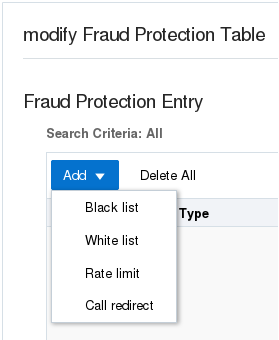
The Web GUI displays the corresponding dialog for editing.
Telephony Fraud Protection Data Types and Formats
Use the information in the following tables when you create or edit a fraud protection list in the Add Fraud Protection Entry and Modify Fraud Protection Entry dialogs.
Data Type Descriptions
The following table describes the data types listed in the Type drop-down list.
| from-hostname | The hostname from the SIP FROM header. |
| from-phone-number | The phone number from the SIP FROM header |
| from-username | The user name from the SIP FROM header. |
| to-hostname | The hostname from the SIP TO header. |
| to-phone-number | The phone number from the SIP TO header. |
| to-username | The user name from the SIP TO header. |
| user-agent-header | The SIP User-Agent header. |
Match Value Formats
The following table describes the formats required for the data types.
| hostname | Enter the exact IP address or FQDN. |
| username | Enter the exact user name. For example: joe.user or joe_user. |
| user-agent-header | Enter the exact text match to the SIP User-Agent header. For example: equipment vendor information. |
| phone-number | You can use the following characters for
phone-number:
|
Caution:
The use of encoding characters is especially susceptible to creating overlapping dial pattern matches that can result in unexpected behavior.Create a Telephony Fraud Protection File
When you want to use the Oracle® Enterprise Session Border Controller (E-SBC) to manage telephony fraud protection, the system requires a specified file to use as the source of the fraud protection lists. When you do not want to upload a file from elsewhere, you can create a new file on the E-SBC. You can create more files now or anytime after configuring fraud protection, but the system uses only the file named in the Fraud Protection configuration as the source file. Note that you cannot create a fraud protection file by way of the ACLI. You must use the Web GUI.
- Confirm that the system displays the Expert mode.
Use the following procedure to create a new fraud protection file on the E-SBC, either before or after enabling fraud protection. See "Telephony Fraud Protection Data Types and Formats" for more information about the selections and formats for Type and Match Value.
- When fraud protection is not configured, see "Configure Telephony Fraud Protection - GUI."
- When fraud protection is configured, see "Activate a New Telephony Fraud Protection File -GUI."
Upload a Telephony Fraud Protection File
When you want to use a telephony fraud protection file from another source, you can upload the file to the Oracle® Enterprise Session Border Controller (E-SBC) by way of the Web GUI. You cannot upload the file by way of the ACLI.
- Confirm that the file to upload uses one of the following file extensions: .gz, .gzip, or .xml.
- Log on to the Web GUI directly to the Expert mode. (The system does not allow this procedure when you log on to Basic mode and switch to Expert mode.)
When you upload a fraud protection file, the system puts the file into the /code/fpe directory. The Upload File dialog provides the option to activate the fraud protection file immediately after the upload, or at a later time. For example, you might defer activation because you want to edit the uploaded file before it becomes the active file.
- When fraud protection is not configured, see "Configure Telephony Fraud Protection - GUI."
- When fraud protection is configured, see "Activate a New Telephony Fraud Protection File - GUI."
Configure Telephony Fraud Protection
The telephony fraud protection feature requires configuration, which you can perform from the Oracle® Enterprise Session Border Controller (E-SBC) Web GUI by way of Fraud Protection listed under System on the Configuration tab.
- Confirm that you own the Advanced license.
- Add or upload at least one telephony fraud protection file to the E-SBC.
- Note the name of the telephony fraud protection file that you want to use.
- Login to Expert Mode directly. (The system does not allow this procedure when you login to Basic mode and switch to Expert Mode.)
Use this procedure to enable telephony fraud protection management on the E-SBC. You must also specify the fraud protection file name and activate the configuration. You cannot specify multiple fraud protection files because the system recognizes only one file as the active source file.
Note:
The first time you configure the E-SBC to manage fraud protection, the system activates the file when you save and activate the configuration. After the initial configuration, the system does not refresh the fraud protection file when you save and activate other configuration changes on the E-SBC. The exception occurs when you specify a new file name in the fraud protection configuration, make changes to other configurations, and save and activate all of the changes at one time.Activate a New Telephony Fraud Protection File
When you create or upload a new telephony fraud protection file, you must activate the file before the system can use it as the source of the fraud protection lists. A new file is a file with a different name than one already in the system.
- Create or upload the new file.
- Note the name of the file that you want to activate.
- Confirm that the system displays the Expert Mode. You can activate a fraud protection file from the Web GUI only in Expert Mode.
In the following procedure, the Local Mode establishes the Oracle® Enterprise Session Border Controller (E-SBC) as the source of fraud protection management.
Edit a Telephony Fraud Protection File
When you want to edit a telephony fraud protection file on the Oracle® Enterprise Session Border Controller (E-SBC), use the Web GUI. You cannot edit a telephony fraud protection file from the ACLI.
To edit a fraud protection file, go to the Web GUI and select a file from the list on the File Management page. When you click Edit, the system displays the fraud protection lists in the file. Select a list type and click Edit. The system displays the corresponding dialog for editing the selected type of list. See "Telephony Fraud Protection Data Types and Formats" for more information about the selections and formats for Type and Match Value.
You can use this procedure to edit any fraud protection file, but the system cannot use the file unless it is the file named in the activated configuration. The following procedure assumes editing the configured file.
Configure a Host Route
Use the Host Routes object to insert entries into the Oracle® Enterprise Session Border Controller routing table to steer management traffic to the correct network.
- Confirm that the gateway for this host route is defined as a gateway for an existing network interface.
- Confirm that the system displays the Expert mode.
In the following procedure, note that no two host-route elements can use the same "dest network" address.
Configure the Network Interface
You must configure the network interface of the Oracle® Enterprise Session Border Controller (E-SBC) to communicate with the physical interface and the network.
- Confirm that the physical interface is configured. For more information, see "Physical Interface Configuration."
- Confirm that the system displays the Advanced mode.
Use the Network Interface object to configure the parameters for the network interface, which specifies a logical network interface over which you can configure one or more application SIP interfaces. Note that the E-SBC supports only one network interface.
- For High Availability (HA), configure redundancy. See "Redundancy Configuration" and "Configure Redundancy."
Configure NTP
Use the NTP Config element to associate the Network Time Protocol (NTP) server with theOracle® Enterprise Session Border Controller (E-SBC).
Use the following procedure to configure synchronization of the NTP server with the E-SBC.
Configure the Physical Interface
You must configure the physical interface of the Oracle® Enterprise Session Border Controller to connect to the network.
Use the phy-interface object to configure the physical interface for control, media, and maintenance operations. Perform this procedure for each operation type, which you will select in step 4.
- Configure the Network Interface. See "Configure the Network Interface."
High Availability
High Availability (HA) is a network configuration used to ensure that planned and unplanned outages do not disrupt service. In an HA configuration, Oracle® Enterprise Session Border Controllers (E-SBC) are deployed in a pair to deliver continuous high availability for interactive communication services. Two E-SBCs operating in this way are called an HA node. The HA node design ensures that no stable call is dropped in the event of an outage.
In an HA node, one E-SBC operates in the active mode and the other E-SBCoperates in the standby mode.
- Active. The active member of the HA node is the system actively processing signal and media traffic. The active member continuously monitors itself for internal processes and IP connectivity health. If the active member detects a condition that can interrupt or degrade service, it hands over its role as the active member of the HA node to the standby member.
- Standby. The standby member of the HA node is the backup system. The standby member is fully synchronized with the active member's session status, but it does not actively process signal and media traffic. The standby member monitors the status of the active member and it can assume the active role without the active system having to instruct it to do so. When the standby system assumes the active role, it notifies network management using an SNMP trap.
The E-SBC establishes active and standby roles in the following ways.
- If an E-SBC boots up and is alone in the network, it is automatically the active system. If you pair a second E-SBC with the first one to form an HA node, the second system automatically establishes itself as the standby.
- If both E-SBCs in the HA node boot up at the same time, they negotiate with each other for the active role. If both systems have perfect health, then the E-SBC with the lowest HA rear interface IPv4 address becomes the active E-SBC. The E-SBC with the higher HA rear interface IPv4 address becomes the standby E-SBC.
If the rear physical link between the twoE-SBCs is unresponsive during boot up or operation, both will attempt to become the active E-SBC. In this circumstance, processing does not work properly.
- it does not receive a checkpoint message from the active E-SBC for a certain period of time.
- it determines that the active E-SBC health score declined to an unacceptable level.
- the active E-SBC relinquishes the active role.
To produce a seamless switch over from one E-SBC to the other, the HA node members share their virtual MAC and virtual IP addresses for the media interfaces in a way that is similar to Virtual Router Redundancy Protocol (VRRP). Sharing these addresses eliminates the possibility that the MAC address and the IPv4 address set on one E-SBC in an HA node will be a single point of failure. Within the HA node, the E-SBCs advertise their current state and health to one another in checkpointing messages to apprise each one of the other one's status. Using the Oracle HA protocol, the E-SBCs communicate with UDP messages sent out and received on the rear interfaces. During a switch over, the standby E-SBC sends out an ARP request using the virtual MAC address to establish that MAC address on another physical port within the Ethernet switch. To the upstream router, the MAC address and IP address are still alive. Existing sessions continue uninterrupted.
Configure the Acme Packet 1100 for HA
The details in the procedures for configuring High Availability (HA) on the Acme Packet 1100 differ from configuring HA for other models of the Oracle® Enterprise Session Border Controller because the Acme Packet 1100 has a single management interface and it shares the wancom0 port for HA operations.
Use the following Expert Mode procedures to configure the Acme Packet 1100 for HA operations. You must perform the physical interface configuration twice. One configuration sets the Management operations the other configuration sets the Media operations.
- Configure the physical interface for management. See "Configure the Physical Interface."
- Configure the physical interface for media. See "Configure the Physical Interface."
- Configure the network interface with addresses for the Primary and Secondary devices. See "Configure the Network Interface."
- Configure the peers for redundancy. See "Configure Redundancy."
Configure Redundancy
Use the Redundancy Config element to configure the parameters to support redundancy for a High Availability (HA) pair of Oracle® Enterprise Session Border Controller (E-SBC) devices.
- Confirm that the physical interface for Control, the physical interface for Media, and the Network interface on the primaryE-SBC are configured for HA pairing.
Perform this procedure to configure redundancy for High Availability (HA) pairing of the primary E-SBC and the secondary E-SBC.
SNMP Trap Receiver
A trap receiver is an application used to receive, log, and view SNMP traps for monitoring the Oracle® Enterprise Session Border Controller (E-SBC).
An SNMP trap is the notification sent from a network device, such as an E-SBC, that declares a change in service. You can define one or more trap receivers on an E-SBC for redundancy or to segregate alarms with different severity levels to individual trap receivers. Each server on which an NMS is installed should be configured as a trap receiver on each E-SBC managed by an NMS.
You can select a filter level threshold that indicates the severity level at which a trap is sent to the trap receiver. The following table maps Syslog and SNMP alarms to trap receiver filter levels.
| Filter Level | Syslog Severity Level | (SNMP) Alarm Severity Level |
|---|---|---|
| All | Emergency (1)
Critical (2) Major (3) Minor (4) Warning (5) Notice (6) Info (7) Trace (8) Debug (9) |
Emergency
Critical Major Minor Warning |
| Critical | Emergency (1)
Critical (2) |
Emergency
Critical |
| Major | Emergency (1)
Critical (2) Major (3) |
Emergency
Critical Major |
| Minor | Emergency (1)
Critical (2) Major (3) Minor (4) |
Emergency
Critical Major Minor |
When configuring the trap-receiver element for use with Network Management Systems, Oracle recommends setting the filter-level parameter to All.
Configure an SNMP Trap Receiver
You can define one or more SNMP trap receivers on an Oracle® Enterprise Session Border Controller (E-SBC) for redundancy or to segregate and send alarms with different severity levels to individual trap receivers.
- Confirm that SNMP is configured.
- Note the names of users who are allowed to receive secure traps.
Oracle recommends that you configure each server with an NMS installed as a trap receiver on each E-SBC managed by an NMS. When configuring the trap-receiver element for use with Network Management Systems, Oracle recommends setting the filter-level parameter to All.
SNMP Community
A Simple Network Management Protocol (SNMP) community is a grouping of network devices and management stations used to define where information is sent and accepted. An SNMP device or agent might belong to more than one SNMP community. SNMP communities provide a type of password protection for viewing and setting management information within a community.
An SNMP community is a string used as a password by the SNMP manager to communicate with the SNMP agent. The SNMP community string allows access to statistics of other devices. The access is used to support the monitoring of devices attached to the network for conditions that warrant administrative attention. When an SNMP community is configured, the Oracle® Enterprise Session Border Controller (E-SBC) sends the community string along with all SNMP requests.
A community name value can also be used as a password to provide authentication, thereby limiting the NMS that has access to an E-SBC. With this field, the SNMP agent provides trivial authentication based on the community name that is exchanged in plain text SNMP messages. For example, public.
- Read-only. Allows GET requests. (Default)
- Read/Write. Allows both GET and SET requests.
IPv4 addresses that are valid within this SNMP community correspond with the IPv4 address of NMS applications that monitor or configure this E-SBC. Include the IPv4 addresses of each server on which an NMS is installed.
Only devices that support SNMPv1 and SNMPv2c protocol can use SNMP community strings. SNMPv3 uses username and password authentication, along with an encryption key.
Configure SNMP Community
Configure a Simple Network Management Protocol (SNMP) community to support the monitoring of devices, such as the Oracle® Enterprise Session Border Controller (E-SBC), attached to the network for conditions that warrant administrative attention.
- Confirm that SNMP is configured.
- Note the IP addresses that you want for this community.
Use this procedure to group network devices and management stations, and to set the access rights for the community. If you want to narrow the scope of the this community, use the Network Addresses option to specify one or more subnets. See "Subnet Ranges for SNMP Community" for more information.
Note:
Only devices that support SNMPv1 and SNMPv2c protocol can use SNMP community strings. SNMPv3 uses username and password authentication, along with an encryption key.Configure Subnet Ranges in SNMP Community
The SNMP system can dynamically originate SNMP GET requests from any host among a wide range of IP addresses. Due to the distributed nature of a typical network, the SNMP GET request may come from any IP address on an /8 netblock. It is not feasible to add all 16,777,216 possible IP addresses, one-by-one, to the SNMP Community configuration. The solution for the Oracle® Enterprise Session Border Controller (E-SBC) is to allow subnet ranges in the SNMP Community configuration. In this way, the (E-SBC) can accept SNMP GET requests from any host in the specified subnet.
You can configure the subnet range from the ACLI and the Web GUI by way of the IP Addresses parameter in the SNMP Community configuration object.
The IP Addresses parameter accepts subnet addresses in address prefix format (<Net_addr>/<Net_mask>), for example, 10.0.0.0/24. For an exact match, omit the number of bits, for example, 10.196.0.0. For multiple entries, use the parenthesis separated by comma format, for example, (172.16.0.0/16,192.168.4.0/24).
Configure System Config
The System Config configuration object contains attributes and sub-objects that you use to configure system-level operations for the Oracle® Enterprise Session Border Controller (E-SBC).
Time Division Multiplexing
Oracle® designed the Time Division Multiplexing (TDM) functionality for companies planning to migrate from TDM to SIP trunks by using a hybrid TDM-SIP infrastructure, rather than adopting VoIP-SIP as their sole means of voice communications. The TDM interface on the Oracle® Enterprise Session Border Controller (E-SBC) provides switchover for egress audio calls, when the primary SIP trunk becomes unavailable. You can use TDM with legacy PBXs and other TDM devices.
- Only the Acme Packet 1100 and the Acme Packet 3900 platforms support TDM, which requires the optional TDM card.
- TDM supports bidirectional calls as well as unidirectional calls.
- TDM operations require you to configure TDM Config and TDM Profile, as well as local policies for inbound and outbound traffic.
- The software upgrade procedure supports the TDM configuration.
- Options for the Acme Packet 1100 and the Acme Packet 3900 platforms include Calling-Line Identification Presentation (CLIP) and Connected-Line Identification Presentation (COLP).
- Options for the Acme Packet 1100 platform include the four-port Primary Rate Interface (PRI), the Euro ISDN Basic Rate Interface (BRI), and the Foreign Exchange Office-Foreign Exchange Subscriber (FXO-FXS) card.
Interface Requirements
PRI—Digium1TE133F single-port or Digium 1TE435BF four-port card.
BRI—Digium 1B433LF four-port card
FXS—Digium 1A8B04F eight-port card, green module (ports 1-4)
FXO—Diguim 1A8B04F eight-port card, red module (ports 5-8)
Notes
When you deploy either the Acme Packet 1100 or the Acme Packet 3900 in a High Availability (HA) pair, the active system cannot replicate calls between SIP and TDM to the standby system.
The Acme Packet 1100 does not support HA for the PRI, BRI, and FXO-FXS interfaces.
Time Division Multiplexing Configuration
To perform Time Division Multiplexing (TDM) operations on the Oracle® Enterprise Session Border Controller (E-SBC), you must enable TDM, specify the parameters for the interface in use, run the TDM configuration wizard, and create local policies for routing TDM traffic.
- Configure the
TDM
Config element and its corresponding sub-elements. The
TDM
Config element, located under
System, contains the
parameters that are common to all TDM configurations. The sub-elements contain
the particular parameters for the interface that the system detects in use on
the
E-SBC. The system
displays the sub-elements, as follows:
- When the E-SBC detects either the Primary Rate Interface (PRI) or the Basic Rate Interface (BRI) interface, TDM Config displays the TDM Profile sub-element with the parameters that correspond to the interface. See "Primary Rate Interface Support" and "Basic Rate Interface Support."
- When the E-SBC detects the Analog interface, TDM Config displays both the FXO Profile and the FXS Profile sub-elements with the parameters that correspond to the interface. See "Foreign Exchange Office-Foreign Exchange Subscriber Support."
- Run the TDM configuration
wizard to complete the configuration. The wizard creates the realm, SIP
interface, steering pools, and other necessary configuration elements including
the network interface and the phy-interface for SIP call routing. With SRTP
enabled (default), the wizard also creates the
Media Sec
Policy object, enables the
Secured
Network attribute for the
SIP Interface
object, and configures the
Media Sec
Policy attribute for
Realm
Config. You can run the wizard from either the Web GUI (Set TDM
Configuration) or the ACLI (Setup TDM).
The E-SBC requires running the TDM configuration wizard only after the initial TDM configuration. The system does not require you to run the wizard after you make changes to the existing configuration.
Note:
When the Oracle Session Delivery Manager (SDM) manages the E-SBC, you configure TDM from the SDM and you do not need to run the TDM configuration wizard. See "Time Division Multiplexing (TDM) Settings on the Session Delivery Manager (SDM)" for the required settings. - Configure the local policy for routing traffic through the TDM interface. For unidirectional TDM call routing, the system requires a local policy only for the call direction that you want. For example, inbound-only or outbound-only. For bi-directional TDM call routing, create both inbound and outbound local policies. See "Local Policy Configuration for Time Division Multiplexing."
- ACLI—Use the TDM Config, TDM Profile, FXO Profile, and FXS Profile elements located under System.
- Web GUI—Basic mode. Double-click the TDM icon in the network diagram to display the TDM configuration dialog.
- Web GUI—Expert mode. Use the TDM Config, TDM Profile, FXO Profile, and FXS Profile elements located under System.
- Session Delivery Manager (SDM)—Launch the Web GUI from SDM and use the TDM Config, TDM Profile, FXO Profile, and FXS Profile elements located under system.
Incoming Call Pattern Guidelines
When you configure either the Primary Rate Interface (PRI) or Basic Rate Interface (BRI) interface for Time Division Multiplexing (TDM), you can set a list of extension numbers and match patterns for routing incoming calls. You can specify exact matches as well as patterns that route to a range of destinations.
For example, suppose that a company with 300 employees deploys the Oracle® Enterprise Session Border Controller (E-SBC) and connects to the PSTN network by way of an ISDN interface. The company allocates 300 extension numbers: numbers 7100 - 7399 for employee desk phones, and number 70 for the reception desk so that it is easy to remember.
The service provider assigns the prefix 49331200 to the company, so the reception desk PSTN number becomes 4933120070 and the employee numbers become 493312007100, 493312007101-493312007399.
The incoming pattern in this example will match either the reception desk number or one of the other extensions. When the match is successful, the received number is complete and the call setup can proceed. You can configure TDM to match the reception desk number as a whole: "4933120070," and to match any of the other extensions through a single pattern: "_493312007[1-3]XX". To put these rules together, set the incoming-pattern parameter to the following value: "4933120070|_493312007[1-3]XX".
In match patterns, separate single extension numbers with the vertical bar (|) character. Start a match pattern with the underscore (_) character before the first number of the pattern. Do not use the underscore with an exact match. Type the exact match, starting with the first number because an exact match does not use an extension pattern. Note the meaning of the following characters:
X matches any digit from 0-9
Z matches any digit from 1-9
N matches any digit from 2-9
[1237-9] matches any digit in the brackets (in this example, 1,2,3,7,8,9).
. wildcard, matches one or more characters
! wildcard, matches zero or more characters immediately
Configure the Single-Port Primary Rate Interface
The Acme Packet 1100 and the Acme Packet 3900 support the single-port ISDN Primary Rate Interface (PRI). To configure the PRI interface, you must set the parameters in tdm-config and tdm-profile under system. After you create the configuration, you must run either the Set TDM Configuration wizard from the Web GUI or the setup tdm command from the ACLI to complete the configuration.
- Confirm the presence of the single-port PRI interface on the Acme Packet 1100.
Note that because the single-port interface supports only one profile, you can set either pri_cpe (Customer Premises Equipment) or pri_net (Network) for signaling. The setting you choose depends on the setting at the other end of the connection. Set this configuration to the opposite of the other end. For example, when the setting at the other end is pri_net, set pri_cpe in this configuration.
Note:
The system requires the four-port interface to support profiles for both pri_cpe and pri_net.- Run the TDM configuration wizard.
- Configure the inbound and outbound TDM local policies.
Configure the Four-Port Primary Rate Interface
The Acme Packet 1100 and the Acme Packet 3900 support the four-port ISDN Primary Rate Interface (PRI) for carrying multiple Digital Signal 0 (DS0) voice and data transmissions between the network and an endpoint. To configure the PRI interface, you must set the parameters in tdm-config and tdm-profile under system. After you create the configuration, you must run either the Set TDM Configuration wizard from the Web GUI or the setup tdm command from the ACLI to complete the configuration.
- Confirm the presence of the four-port PRI.
- Plan the number of TDM profiles that you want. (You can add or delete profiles later, if your needs change.)
When the Oracle® Enterprise Session Border Controller (E-SBC) detects the PRI interface interface, it displays the corresponding configuration parameters. In the PRI configuration, the line mode that you specify dictates certain corresponding settings. You can set either t1 or e1 for line-mode, but note that each one requires certain uniquely compatible settings. For example, when you specify the t1 line mode you must specify esf for the framing-value. Do not specify an e1 value for the t1 line mode or a t1 value for the e1 line mode. The following procedure shows the specific t1 and e1 settings, where required.
- Run the TDM configuration wizard.
- Configure the inbound and outbound TDM local policies.
Configure the Basic Rate Interface
To configure the Basic Rate Interface (BRI) card, you must set the parameters in TDM Config and TDM Profile under System. Note that the system supports coexisting profiles for both bri_cpe (Customer Premises Equipment) and bri_net (Network). After you create the configuration, you must run either the Set TDM Configuration wizard from the Web GUI or the Setup TDM command from the ACLI to complete the configuration.
- Confirm the presence of the BRI interface on the Acme Packet 1100.
- Plan the number of TDM profiles that you want. (You can add or delete profiles later, if your needs change.)
When the Oracle® Enterprise Session Border Controller (E-SBC) detects the BRI interface, it displays the corresponding parameters and inserts certain values that you cannot change.
- Run the TDM configuration wizard.
- Configure the inbound and outbound TDM local policies.
Configure Inbound TDM Policy
Time Division Multiplexing (TDM) operations require policies for directing traffic to and from the TDM realm. In the following procedure, you specify the attributes for inbound TDM traffic.
- Configure TDM.
For the Policy priority parameter, the priority hierarchy from lowest to highest is none, normal, non-urgent, urgent, emergency. None means no priority. Each higher priority handles sessions at its level plus the sessions in the priorities above it. For example, non-urgent also handles sessions for urgent and emergency.
In the following procedure, the to-address and from-address can match the caller and called phone number or you can use any of the valid values noted. Note that you must use tdmRealm, which is case sensitive, for source-realm.
- If your deployment requires an outbound TDM local policy, see "Configure the Outbound TDM Policy."
Configure the Outbound TDM Policy
Time Division Multiplexing (TDM) operations require policies for directing traffic to and from the TDM realm. In the following procedure, you specify the attributes for outbound TDM traffic.
For the Policy priority parameter, the priority hierarchy from lowest to highest is none, normal, non-urgent, urgent, emergency. None means no priority. Each higher priority handles sessions at its level plus the sessions in the priorities above it. For example, non-urgent also handles sessions for urgent and emergency.
For the next-hop parameter in policy-attributes, use the name of the tdm-profile that you want associate with this policy.
- If your deployment requires an inbound TDM local policy, see "Configure the Inbound TDM Policy."
Configure Outbound Local Policy with TDM Backup
To complete the Time Division Multiplexing (TDM) configuration for redundancy, you must configure the TDM local routing policy.
- Confirm that a TDM configuration exists.
- Confirm that a policy exists for the realm.
To configure TDM for backup, add the tdm profile as a second attribute to the local policy.
- Access the Local Policy configuration object: Configuration, Session Router, Local Policy, Add.
- On the Add local policy page, under Policy attributes, click Add.
- On the Add Local Policy / policy attribute page, select tdm:<profilename> from the Next Hop drop down list.
- Click OK.
- Save the configuration.
- Save the configuration.
Add an FXO-FXS Profile
When your deployment requires Foreign Exchange Office-Foreign Exchange Subscriber (FXO-FXS) profiles, you can add up to four profiles each to support different attributes at different endpoints. For example, you might create profiles based on user name, department, location, and so on. You can create FXO profiles only, FSO profiles only, or both. To configure the FXO-FXS profiles, go to TDM Config under System, and create the profiles that you need.
- Requires the FXO-FXS interface
The configuration process includes configuring TDM Config and a corresponding FXO Profile or FXS Profile.
- Run the TDM Configuration Wizard.
- Configure the inbound and outbound TDM local policies.
Perform FXO Port Tuning
Tuning the Foreign Exchange Office (FXO) ports can help the echo canceller to work more efficiently. The setup fxotune run command creates the fxotune configuration file, which contains the script that fine tunes the Digium Asterisk Hardware Device Interface (DAHDI) FXO channels, and restarts the system. The tuning takes place during the restart. After FXO tuning, the system saves the result in a configuration file that is automatically applied after each subsequent restart. No additional user action is necessary.
- Configure one or more FXO profiles and activate the configuration.
Note that the following procedure requires a system restart, which can take longer than usual due to the tuning process.
- From the command line, type setup fxotune run.
- Restart the E-SBC.
Reset the FXO Port Tuning Defaults
If you ever want to reset the setup fxotune run boot parameter, use the setup fxotune reset command. The command resets the boot parameter for setup fxotune run to the default tuning values and removes the fxotune configuration file.
Note that the following procedure requires a system restart.
- From the command line, type setup fxotune reset.
- Restart the E-SBC.
Configure Fax Transcoding for the Acme Packet 1100
The system requires two codec policies, two local policies, and two realms to support fax transcoding.
- Before you begin, configure one realm that points to the Internet and one realm that points to the Time Division Multiplexing (TDM) interface.
For example, suppose you name the internet-facing codec policy "Remote" and you name the TDM-facing codec policy "TDM." Use the following guidelines for configuration:
- In the "Remote" codec-policy, set allow-codecs to T.38 PCMU PCMA and set add-codecs-on-egress to T.38OFD.
- In the "TDM" codec-policy, set allow-codecs to PCMU PCMA and set add-codecs-on-egress to G711FB.
- In the "Remote" local-policy, set source-realm to remote.
- In the "TDM" local-policy, set source-realm to tdmRealm.
- In the "Remote" realm-config, set identifier to remote, set the codec-policy type, and set codec-manip-in-realm to enabled.
- In the "TDM" realm-config, set identifier to tdmRealm, set the codec-policy type, and set codec-manip-in-realm to enabled.
Configure Overlap Dialing for Call Routing
When you enable overlap dialing and set the incoming match pattern, the Oracle® Enterprise Session Border Controller (E-SBC) can work with the information in the SETUP message to successfully route calls through the Primary Rate Interface (PRI) and Basic Rate Interface (BRI) in a Time Division Multiplexing (TDM ) deployment.
- Plan the match patterns that you want for incoming calls. See "Incoming Call Patterns Guidelines" for rules and syntax.
- Confirm that the TDM Profile that you want to enable for overlap dialing exists.
Note:
If the TDM Profile that you want does not exist, you can set the Overlap Dial and Incoming Pattern parameters when you create the profile. The following procedure assumes the profile already exists.Access TDM Config and use the TDM Profile sub-element to set the OverlapDial and Incoming Pattern parameters.
Web Server Configuration
The Web server is a software application that helps to deliver Web content that you can access through the Internet. The Web server runs the Enterprise application called the Web GUI.
Every Web server has an IP address and sometimes a domain name. For example, if you enter the URL http://www.acmepacket.com/index.html in your browser, the browser sends a request to the Web server with domain name is acmepacket.com. The server fetches the page named index.html and sends it to the browser.
If you enter http://132.45.6.5, and this address has been configured by your Administrator to access the Web GUI, the server fetches the page and displays the Web GUI logon page to your browser.