2 Feature Description
This chapter describes the Stateful Applications feature.
2.1 Introduction
SS7 Firewall - Stateful Applications allows the Signaling Transfer Point (STP) to validate the messages coming in for a subscriber roaming out by validating them against the Visitor Location Register (VLR) when the subscriber was last seen by the Home Location Register (HLR). Once the HLR provides a validity of the new VLR, the EAGLE lets the message into the network. If the message is not validated, it is handled per configuration (either silent discard, fallback, or respond with error).
The message forwarding from LIM to SFAPP cards will only work with IPSG+GTT SLIC cards. For all other LIM cards, messages will be forwarded to the SCCP cards, which will then forward the message to the SFAPP SLIC cards.
2.2 Supported MAP Operations
The following MAP Operations are supported by the Stateful Applications feature.
Table 2-1 Supported MAP Operations
| MAP Operation | OpCode | Application Context (AC) | AC Code |
|---|---|---|---|
| sendParameters | 9 | infoRetrieval /v1 | 14 |
| Registers | 10 | networkFunctionalSs | 18 |
| Erases | 11 | networkFunctionalSs | 18 |
| Activates | 12 | networkFunctionalSs | 18 |
| deactivates | 13 | networkFunctionalSs | 18 |
| interrogates | 14 | networkFunctionalSs | 18 |
| authenticationFailureReport | 15 | authenticationFailureReport /v3 | 39 |
| registerPassword | 17 | networkFunctionalSs | 18 |
| processUnstructuredSS-Data | 19 | networkFunctionalSs /v1 | 18 |
| mo-forwardSM | 46 | shortMsgMO-Relay | 21 |
| noteSubscriberPresent | 48 | mwdMngt/v1 | 24 |
| beginSubscriberActivity | 54 | networkFunctionalSs /V1 | 18 |
| restoreData | 57 | networkLocUp/v2 | 1 |
| processUnstructuredSS-Request | 59 | networkUnstructuredSs v2 | 19 |
| readyForSM | 66 | mwdMngt /v2/v3 | 24 |
| purgeMS | 67 | istAlerting /v2/v3 | 4 |
| purgeMS | 67 | msPurging /v3 | 27 |
| ss-Invocation-Notification | 72 | ss-InvocationNotification | 36 |
| statusReport | 74 | reporting | 7 |
| istAlert | 87 | istAlerting /v3 | 4 |
| NoteMM-Event | 89 | mm-EventReporting | 42 |
| updateLocation | 2 | networkLocUp | 1 |
| updateGprsLocation | 23 | gprsLocationUpdate/v3 | 32 |
| sendAuthenticationInfo | 56 | infoRetrieval /v2/v3 | 14 |
2.3 VLR Validation
As seen in the following figure, VLR Validation uses the information stored in the HLR about the current VLR to validate the VLR from which the message is received.
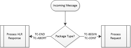
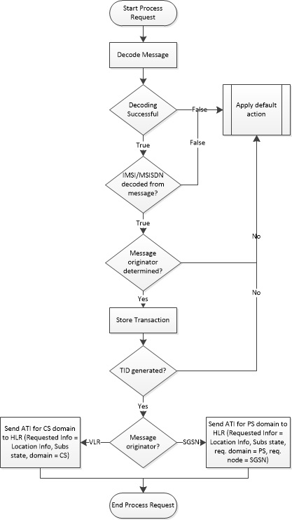
Figure 2-1 Call Flow for VLR Validation
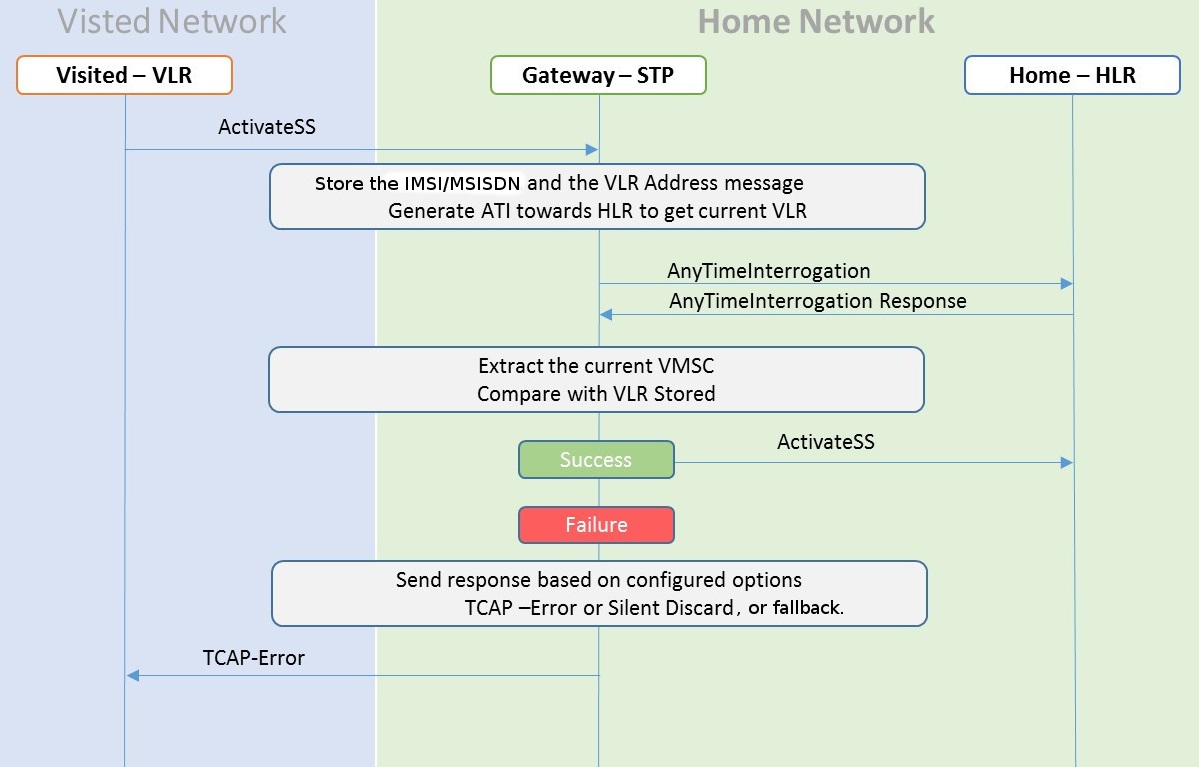
- The incoming message will
be decoded.
- An Error will be generated in case of decode failure.
- The message information will be stored in the local database.
- The Any Time Interrogation
(ATI) request will be generated towards the HLR.
- The ATI Request will be coded so that Acknowledgment is received on the same SLIC card, as the DB is local.
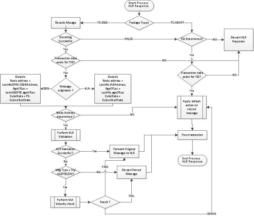
- For a successful response
from the HLR:
- The ATI Response will be decoded to get the current VLR address.
- The current VLR address will be compared with the CgPA stored in the local database for the subscriber.
- On a successful Match, the message will be routed as per the GTT result.
- In case of failure,
- Send the configured response.
- Increment the measurement for failed messages.
The ATI sent to HLR must be formatted as follows:
- MTP OPC=EAGLE SID, MTP DPC = HLR PC
- SCCP CGPA (RI = SSN, PC = EAGLE SID, SSN = <SSFAPP SSN>, SCCP CDPA (received message CDPA)
- TCAP BEGIN with valid MAP dialogue portion (as per MAP specification)
- TCAP DTID = unique OTID generated for each ATI (The DTID will not be reused within 5 seconds)
- ATI details: IMSI = IMSI/MSISDN received in received message, and other mandatory parameters
The EAGLE will validate the ATI_ACK received from the HLR. A valid ATI_ACK message is defined as:
- It is a well formatted ANSI or ITU SCCP UDT, non-segmented XUDT message, with a valid TCAP END message, with valid dialogue portion, and single component in the component portion as return result with operation code = ATI_ACK
- Value of DTID received in TCAP END matches with one of the ongoing transactions
- Component type is a return result and contains ATI_ACK
- VMSC digits are received in ATI_ACK
2.4 Velocity Check Using ATI
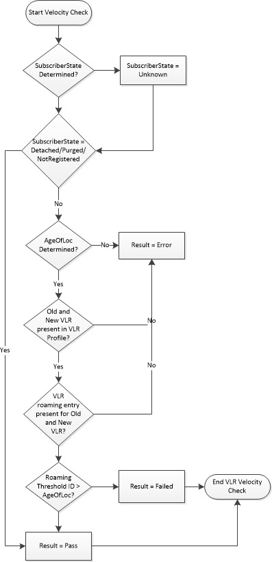
As seen in the following figure, Velocity Check using ATI uses the information stored in the HLR about the current VLR and the age of location parameter to identify if the new VLR is reachable from the current VLR stored in HLR.
This use case is dependent on the validity of the information stored in the VLR and the T3212 timer (periodic update location timer). This timer governs the rate at which the mobile subscriber autonomously updates their location. In case the time distance between two networks is less than the value of T3212 timer configured for the network, this use case test would provide false positives since the location age information would not have been properly updated in the VLR.
The assumption for successful execution of this use case are:
- The First location update can be identified using the IMSI only in the address.
- The Age of Location provided by HLR is accurate.
- The quantum of information (Age of Location) will not be less than the time to get travel.
The ATI-based check can be completed in a reasonable amount of time for Location Update to succeed.
Figure 2-2 Call Flow for Velocity Check Using ATI
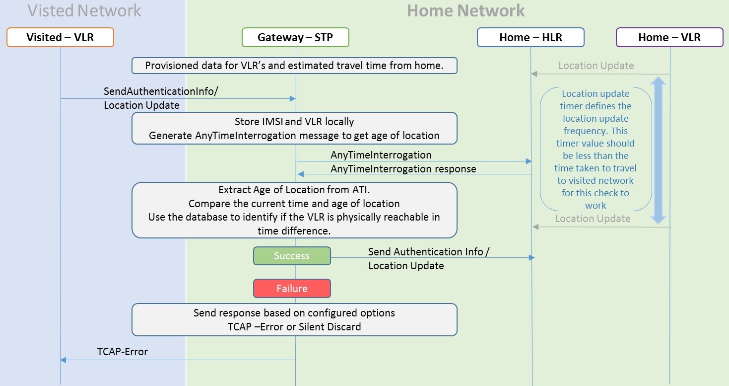
- A local database on EAGLE will be configured to identify the network locations (using country codes for VLR addresses) and the shortest amount of time it may take to travel between them.
- The incoming message will be
decoded:
- An Error will be generated in case of decode failure.
- A Measurement will be pegged for the decode failure with OpCode and CgPA.
- The message information will be stored in the local database.
- The ATI request will be generated toward the HLR identified in the CdPA of the incoming message. The ATI request will be coded so that it is received on the same SLIC card, as DB is local.
- In case the HLR sends a
failure in the ATI response:
- A measurement will be pegged to identify HLR error corresponding message from CgPA (VLR).
- For a success response, extract the Age of Location from the ATI Response message and the VMSC address in the HLR.
- In case the VLR, from which the SAI/LU was received, matches the VLR in the ATI response, don't do anything.
- In case the VLR addresses do
not match:
- Calculate the time difference between the current time and the Age of Location.
- Verify the age of location is less than the travel time configured in the local Database.
- In case of time value not within limits:
- A measurement will be pegged.
- Response will be generated based on the configured option.
2.5 Graylisted VLR Validation Using IMEI
Graylisted VLR Validation Using IMEI challenges the VLR after the Update Location procedure is completed by asking for the IMEI information in the provide subscriber information message.
This use case addresses these MAP 3.2 messages:
- Update Location/GPRS Update Location - VLR or the SGSN initiates the MAP send authentication information procedure to retrieve authenticated information from the HLR.
- Provide Subscriber Info - This message is sent by EAGLE to the VLR or SGSN to retrieve the subscriber state, location information and, in this case, IMEI.
- Provide Subscriber Info ACK - This message is sent from VLR or SGSN to the EAGLE as an acknowledgement to the PSI.
- AnyTime Interrogation – This message is sent as part of use cases 1 and 2.
- Purge MS - If a roaming subscriber is suspected as a malicious or fake user, EAGLE generates this message to HLR. Upon receiving this message, HLR marks the subscriber unreachable.
2.5.1 Graylisted VLR Validation Flow Chart
This use case challenges the visited VLR after the procedure for location update has been completed by asking for the subscriber’s IMEI information in a PSI message. After that, one of these actions is taken:
- The IMEI information can then be compared against an external database to validate the IMEI and consequently the VLR by either allowing the original procedure to complete or fail it by initiating in a Purge MS operation, or
- The IMEI information can be added to/updated in the external database if the VLR is trusted and the IMEI is validated.
Figure 2-7 Graylisted VLR Challenge
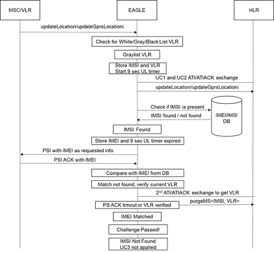
- Incoming UL message on the LIM card, either from the VLR or SGSN, is forwarded to the SCCP card by GT routing using GTT action for SFAPP. The SCCP card uses GTT based on SFAPP action to forward the message to the SFAPP card.
- UL message is decoded on the SFAPP card. An error is generated in case of decoding failure. Details of the decoding failure errors are described in Decoding Errors Generated EAGLE.
- The VLR address is checked to see if it is white/gray/blacklisted in the VLR database on the card. If graylisted, IMSI and the VLR address information is stored in a local data structure for further challenging the visited VLR with IMEI information for the mobile subscriber.
- After extracting the IMSI and VLR address, the UL message is forwarded to the CdPA(HLR).
- UL timer of 9 seconds timeout value is started to wait for update location procedure to complete on the mobile subscriber by the visited VLR to HLR. At the expiry of the UL timer, IMEI challenge begins.
- The IMEI information for the subscriber is retrieved from the EEDB, if present. If not found, use case 3 is terminated and no further action is taken.
- If found, the IMEI is stored and a PSI message is
encoded by EAGLE with the IMSI and VLR from the original UL message and sent to
the visited VLR. The SCCP portion of the PSI message is encoded to route on SSN
SFAPP. CgPA from the original UL message is copied as the CdPA. CGPA is created
from the
psirescgmodidparameter ofent-gtmodcommand. TCAP layer of the PSI message is filled with the PSI opcode and IMSI tag/length/value, and requested information in the component portion is updated with IMEI tag/length fields. Transaction ID for an outgoing PSI message is encoded as described in Routing of PSI Response Back to Originating SFAPP Card. - Encoded PSI message is routed on SSN SFAPP to the
SCCP card and is further GTT routed on to the visited VLR by the LIM card. A
transaction timer of 4 seconds timeout (with a unique
transaction_id) is started to track the PSI message sent. If the timer expires, the challenge is considered to have failed and a purgeMS is generated as described in 13. - When a PSI ACK arrives at
EAGLE, upon arrival of the MSU at the SCCP card, if the
mate_idin the TCAP transaction ID matches with the storedSTP_IDof EAGLE, PSI ACK is sent to the SFAPP card. The details of the implementation of this functionality on the SCCP card is discussed in Routing of PSI Response Back to Originating SFAPP Card. - FAILACTID is enforced on
the SFAPP card for the IMEI challenge just like in the case of velocity check
challenge. If the IMEI decoded from the PSI_ACK does not match the IMEI
retrieved from the EEDB and the VLR is graylisted, the provisioned FAILACTID is
enforced.
- If the FAILACTID is FALLBACK, then the PSI_ACK is not decoded (for example, no further data is decoded from the PSI_ACK) and the IMSI is not marked with an ms_purged_flag in HLR.
- If the FAILACTID is DISCARD, then it is used to send a purgeMS message to the HLR for a given IMSI.
- If the FAILACTID is not provisioned by the customer, every PSI_ACK message is decoded at the SFAPP card by matching TID (transaction_index) in the TCAP information with the appropriate PSI_ACK_TID and looking for PSI map_opcode to look for the IMEI tag in the ACK message. If the IMEI tag is present and the value matches with what was retrieved from the EEDB, the IMEI challenge is considered as passed. An absent IMEI tag in the PSI_ACK is considered a failure.
- An IMEI challenge failure
results in generating another ATI to the HLR (as in use case 2) to verify the
subscriber’s current VLR. Upon receiving the ATI ACK or a timeout, a purgeMS is
sent by EAGLE to the HLR. The encoding of the purgeMS message is as follows:
- HLR address (CdPA - used at SCCP layer) is obtained by the saved copy of the UL message in the local data structure.
- CgPA is the EAGLE self PC.
- The SCCP portion of the PSI message is encoded to route on SSN SFAPP.
Note:
If the timer for the ATI ACK expires, no UIM displays indicating the expiration. - If the challenge has failed, the SFAPP categorizes the VLR as an intruder and generates a purgeMS message to the HLR for the subscriber from the original UL. The purgeMS incorporates the IMSI tag/length/value. The important piece in the TCAP layer component portion is msPurgingContext 5 bytes value which is as follows: 0x02-operation tag 0x01-length, 0x43-purge MAP opcode 0xa3-sequence tag, 0x00-length. There is no requested information built into the purgeMS message at the TCAP layer. EAGLE does not expect and process response from HLR for purgeMS. Hence, the transaction ID at the TCAP has 4 bytes OTID as 'ff ff ff ff' to indicate an INVALID TID.
- HLR marks the mobile subscriber as MS_purged_flag so that any request for routing information for a mobile-terminated call or mobile-terminated short message is treated as if the MS were not reachable.
2.5.2 Decoding Errors Generated EAGLE
The following decoding errors can result from the call flow:
- Unsupported Opcode is generated when invalid value is provided in the opcode filed by the VLR/SGSN
- Invalid message type error is generated on an invalid component type. An invalid component type isn't equal to TCAP_ITU_RETURN_RESULT_LAST
- Transaction ID is not found in the transaction_db error
- Unsupported message type error for the case of invalid SCCP MSU type
- TCAP decoding failure errors
- PSI ACK not received
- Purge MS error
- PSI encoding error
2.5.3 PSI Encoding and Decoding of the PSI_ACK Extended
- As a special identification aid, a special TCAP/MAP invoke_id is embedded in the PSI message as a special fixed value. This invoke_id is not user configurable.
- When the PSI_ACK returns to the SCCP card, if the map_opcode is not present, the combination of the special invoke_id/TCAP_END and return_result_last is used to validate that the PSI_ACK received has been generated by the Eagle and the PSI_ACK can be decoded for IMEI validation.
2.5.4 Routing of PSI Response Back to Originating SFAPP Card
Transaction ID Encoding and Decoding
The SFAPP card encodes the Originating Transaction ID in the PSI message in this format to identify the STP Node that generated the message:
struct {
t_u8 card_loc;
t_u8 ref_count:4;
t_u8 mate_id:4;
t_u16 trans_index;
}field
The Mate ID is the index of the location of the STP’s self ID provisioned in the STP mate table. The mate table is populated with the STP’s mate point codes as well as its own. If the mate tables of each STP that forms a pair/quad contains the same point codes, the order of the tables for each node is guaranteed to be the same.
PSI Response Handling on SCCP Card
- When the PSI Response is received on the LIM card, it does the normal processing and sends that message to the SCCP card.
- When the message is received on the SCCP card, it applies the GT rules on that message.
- After applying GT rules, it filters the message
with these rules. If all the rules match, then it goes to step 4,
otherwise it does the normal GT processing:
- SFAPP GTT action is provisioned for the matching translation or forwarding the message to SFAPP SS.
- Dlg Type is END or ABORT
- Comp type is Return result last/Abort/Return error
- OpCode is PSI response
- Invoke ID is some high value 0x7F
- Decode the Mate ID from
the destination Transaction ID and match the Mate ID in the message with the
Mate ID stored in the table (to verify the response for EAGLE-generated
request).
- If Mate ID matches with the ID stored in the table and the entry is the node's self ID, then forward that to the SFAPP card.
- Or forward that to the correct mate node that generated the request
- If Mate ID does not match with the stored value, do the normal processing.
2.5.5 IMEI Learning Using the EAGLE External Database (EEDB)
Figure 2-8 Whitelisted VLR DB Learn - Whitelisted VLR DB Learning
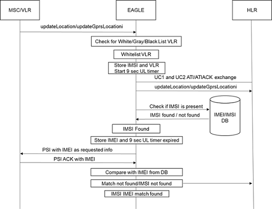
When the UL message has been intercepted by EAGLE, if the VLR is determined to be whitelisted, a query to the EEDB is launched. If the IMSI is not found, when the IMEI is extracted from the PSI_ACK, it is added to the EEDB. If it was found and the data matched to that returned in the PSI_ACK, the record in the EEDB is updated with aging data.
2.6 Intelligent VLR Whitelist
Intelligent VLR Whitelist uses a whitelist that is created as part of learning from the validation attempts defined in VLR Validation and Graylisted VLR Validation Using IMEI.
To implement a whitelist-based, learning-based validation, VLR is implemented where the VLR addresses are validated from tables configured/stored on disk in the STP. The tables are differentiated into 2 classes - Static and Dynamic VLR tables. There are two static VLR tables – a static VLR profile table (same as VLR profile table in use case 2) and a static VLR roaming table (same as VLR roaming table in use case 2). Also, there are two dynamic VLR tables – a dynamic VLR profile table and a dynamic VLR roaming table. The VLR validation process is the same in concept, for example, they block messages until velocity check is applied. But, with the introduction of new tables, EAGLE can now support dynamic VLR learning and populate dynamic VLR tables autonomously from the network traffic. However, the VLR DB UI commands work the same as in use case 2.
Both static and dynamic VLR tables are disk-resident tables on the OAM. The dimensions of static VLR profile and dynamic VLR profile tables are exactly the same. Similarly, the dimensions of static VLR roaming and dynamic VLR roaming tables are exactly the same. The main difference between the two classes of tables lies in the process of their population and maintenance. Static VLR tables are only updated by UI commands whereas dynamic VLR tables are populated by the information learned by EAGLE through network traffic over time. Information flow for static VLR tables is in the form of provisioning (RADB) packets - originating at OAM and terminating at SFAPP cards - which are generated per UI command where information flow for dynamic VLR tables is dictated by sync cycles - originating from secondary SFAPP cards and terminating at OAMs - which are triggered by timers. Network traffic is only received on secondary SFAPP cards, while the primary SFAPP card is always in flow-control and does not process any traffic.
Learning is controlled by these modes using a mode parameter in the new SFAPPOPTS command:
- Learn Mode - This mode allows all unknown VLRs that are learned to be added to the dynamic VLR database, but does not update existing data in any manner.
- Test Mode - This mode validates the unknown VLRs and moves to whitelist/blacklist per thresholds configured. However, no further action is taken (no messages are rejected).
- Active Mode - This mode validates VLRs based on the learned white lists in the system. In case the VLR is not available in the list, the message is rejected.
The term new VLR means the CgPA GT address of the incoming network message is not found either in the Static VLR table nor in the Dynamic VLR table on the SFAPP card where the network message was originally received. These network messages can be messages such as ActivateSS, UpdateLocation, UpdateLocationGPRS, and SendAuthenticationInfo.
Note:
There is no flow-control or recovery mechanism to get the dynamic update buffers lost in transit. For example, if a dynamic update is lost in transit between a secondary SFAPP card and the primary card, the update is relearned when the next message from that VLR is received.2.6.1 Dynamic VLR Whitelisting Flow
Secondary SFAPP Cards
Figure 2-9 Dynamic VLR learning (VLR Whitelisting)
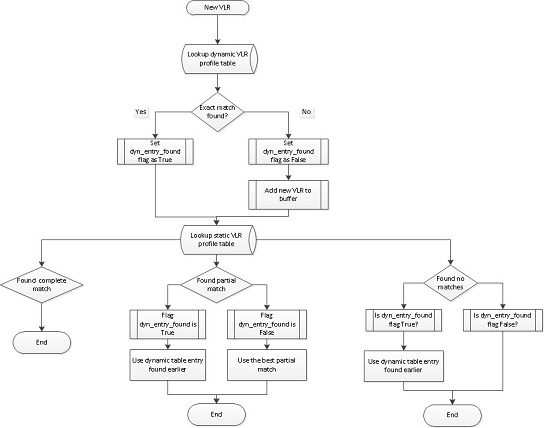
When a new VLR in the incoming network message is received on a secondary SFAPP card, the VLR is first searched in the dynamic VLR profile table. If exact match is found, a control flag - for example, dynamic_entry_found - is set and a subsequent static VLR profile table search is applied. If an exact match is NOT found, the new VLR is added to a buffer, but the static VLR profile table search is still applied. In static table search, there can be three cases:
- Complete match found: If complete match is found, nothing needs to be done.
- Partial match found: If partial match is found, use the best matching partial static VLR profile entry.
- No matches found: If no matches are found for new VLR in static VLR profile table, check the value of dynamic_entry_found flag.
Note:
A secondary SFAPP card only makes one buffer worth up to 48 VLRs in one 500ms cycle. But since there could be n number of secondaries in EAGLE, the primary SFAPP card receives n number of new VLR buffers in one 500ms cycle.Primary SFAPP Cards
Note:
The primary SFAPP card has a second timer of 1-hour duration which is responsible for triggering dynamic VLR table synchronization between SFAPP(P) and OAM card.2.6.2 VLR Velocity Check Flow
Secondary SFAPP Cards
Figure 2-10 VLR Velocity Check
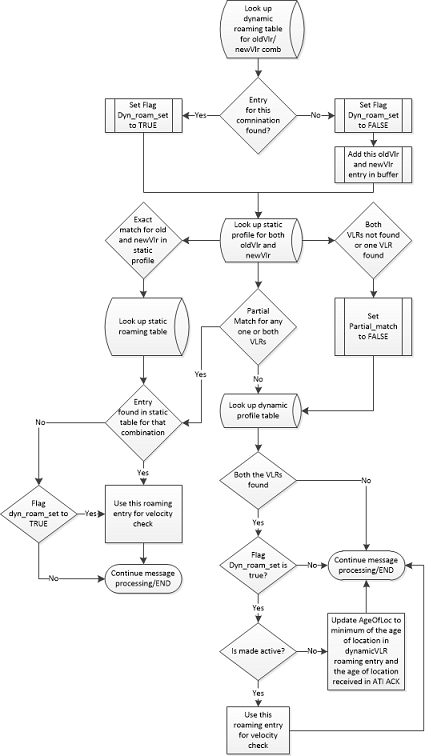
The dynamic VLR roaming table is used on these occasions:
- When both new VLR and old VLR are found in the
dynamic VLR profile table.
In this case, we look up the dynamic VLR roaming table with the dynamic VLR profile table indices of new VLR and old VLR to get threshold and subscriber state. If the threshold value is less than or equal to the age of location found in the ATI ACK, then VLR validation is considered successful.
- When one VLR is found in the dynamic VLR profile
table and the other VLR is found in the static VLR profile table.
In this case, the VLR entry found in the static VLR profile table is duplicated into the dynamic VLR profile table on that SFAPP card. This is done so as to obtain both new and old VLR indices from the same profile table.
For example, say new VLR is found in the dynamic profile table, but the old VLR is found in the static profile table. We replicate the old VLR entry from the static profile table into the dynamic profile table and get the indices of both the new VLR entry and the newly-created old VLR entry from the dynamic profile table. With these indices, the search is performed in the dynamic VLR roaming table to get the threshold, subscriber state, and last activity time.
Note:
If the same combination of old VLR and new VLR is observed again in another VLR validation and the value of age of location is the same as that in the dynamic VLR roaming entry, age of location value in roaming entry is not updated.Note:
If the same combination of old VLR and new VLR is observed again in another VLR validation and the value of age of location is different than that in the dynamic VLR roaming entry, age of location value in roaming entry is updated to a minimum of the age of location in dynamic VLR roaming entry and the age of location received in ATI ACK. Here, we take the minimum of both age of locations since we assume the ATI ACK is always coming from the True VLR since ATI and ATI ACK are internal messages for the SS7 network.For example, say combination of old VLR=123 and new VLR=456 is searched into the dynamic VLR roaming table. A matching entry is found in the table and the age of location entered as 10 hours. But, the value of age of location in the ATI ACK is 8 hours. Then, we update the age of location of the existing dynamic VLR roaming entry to 8 hours using the following formula.
Primary SFAPP Cards
The syncing of the dynamic VLR roaming table is the same as that of dynamic VLR profile table.
2.6.3 Primary Card Selection
With this feature, SFAPP cards are now split into two groups: Primary - having only one member, and Secondary - all other SFAPP cards. To select the primary, the general rule is one having the lowest IMT address is designated as the primary SFAPP card, but if any SFAPP card having higher IMT address becomes active before others and primary cards selection procedure completes on it before other SFAPP cards becomes active, then that SFAPP card continues to be a primary SFAPP card and all the other cards are designated as secondary SFAPP cards. The primary SFAPP card has numerous responsibilities for dynamic VLR information management and therefore, does not process any traffic - its primary duties are to collate the updates from the secondaries and act as a sync between the secondaries and OAMs. The secondary SFAPP cards, however, are the ones that process traffic to inform primary SFAPP card of the new VLRs they have learned individually over time.
- On receiving the DETERMINE_ROLE signal from ADL, the SFAPP manager initializes the SFAPP Role Change Manager. When this is initialized, it starts a 250ms timer on the SFAPP card. This timer is responsible for triggering the role determination algorithm on the SFAPP card.
- When the 250ms timer expires, the SFAPP card checks if it has received a broadcast message from any other SFAPP card in the system indicating the other card has become primary. If no such broadcast message has been received, the SFAPP card checks if it has been 1 second without an incoming broadcast message and if it has not been 1 second, the 250ms timer is restarted. If it has been 1 second without a broadcast message, the SFAPP card sets its state as primary and sends out a broadcast message to all other SFAPP cards in the system indicating so. The primary SFAPP card also puts itself in flow-control since primary SFAPP card does not process any traffic.
- When this broadcast message is received on some other SFAPP card in the system, it checks if its IMT address is less than the IMT address of the card from where the broadcast message is coming. If the check returns FALSE, this SFAPP card sets its state as secondary and starts to process network traffic.
Note:
- If two SFAPP cards in the system become primary at the same time and broadcast their respective messages, each card receives the broadcast message from the other card and compares the IMT addresses, for example, IMT address of itself and the IMT address of the card from which broadcast message was received - and the card which has the lower IMT address becomes the primary SFAPP card while the other becomes a secondary SFAPP card.
- When a primary SFAPP card is re-initialized, the SFAPP card having the lowest IMT address becomes the primary SFAPP card and puts itself in flow-control.
2.6.4 Dynamic Entry Aging
Dynamic entries have an aging process applied to remove dynamic VLR entries, which do not get referenced. An agetime parameter is added to the new SFAPPOPTS command to define an age limit that a dynamic VLR entry must be referenced (updated) within to avoid being aged out/removed.
The aging process is performed per the time interval set in the agetime (in hours) parameter in SFAPPOPTS table. The primary SFAPP card performs the ageing mechanism on dynamic VLR profile and roaming tables by deleting the entries, which were not referenced for the duration set in agetime. Once the ageing mechanism completes on primary SFAPP card, it then syncs the complete tables with secondary SFAPP cards and OAM using the table copy mechanism.
The ageing mechanism is overloaded with the one-hour primary SFAPP to OAM sync. When ageing and one-hour sync intersect, then only the ageing mechanism is performed since it also covers the one-hour sync mechanism.
2.6.5 OAM Processing
Dynamic VLR Table Sync with Primary SFAPP Card
There are two processes on the OAM where dynamic updates and the use of dynamic VLR tables are used.
The primary SFAPP card has a 1-hour timer, on expiry of which it begins the dynamic VLR profile table sync between itself and the active OAM. The beginning of the hourly sync process is indicated using a UIM. At 1-hour timer expiry, the primary SFAPP card sends a signal to the active OAM to indicate the start of the dynamic VLR table sync cycle. On receiving this signal, OAM checks if there are any pending updates that need to be done on dynamic VLR table before sync begins. If there are no updates, the OAM sends back an ACK informing the primary SFAPP card that it is ready for syncing. If there are pending updates, those updates are processed before sending out the ACK. On receiving the ACK from OAM, the primary SFAPP card initiates table copy mechanism and sends three dynamic VLR tables (dbmm, profile, and roaming) to the OAM. The OAM then refreshes its RAM and binary trees. Once the RAM copy of dynamic VLR profile table on the active OAM is updated, the active OAM then sends the updated dynamic VLR profile table to the standby OAM. The standby OAM writes the table in the RAM first and then to its disk.
During this process, access to the dynamic tables must be controlled and no other access can be allowed. Therefore, the following commands are inhibited:
- Chg-db
- Copy-meas
- Copy-disk
- Format-disk
- Act-upgrade
- Rept-stat-db
- FTRA
- RTRV-VLR-PROF
- RTRV-VLR-ROAMING
- ENT-VLR-PROF
- CHG-VLR-PROF
- CHG-TH-ALM
- REPT-STAT-MFC
- ENT-MATE-STP
- DLT-MATE-STP
- RTRV-MATE-STP
- CHG-SFAPPOPTS
- RTRV-SFAPPOPTS
- Rtrv-vlr-prof/rtrv-vlr-roaming - these commands are inhibited for dynamic tables only, that is, access to the static tables is allowed.
The sync process start is signaled by issuing UIM 1316, and sync completion by UIM 1317.
Dynamic VLR Table Sync with Secondary SFAPP Card
When all SFAPP cards are initialized, they download all the required static tables from the OAM. But the OAM sends the dynamic VLR tables only to the primary SFAPP card. It is the responsibility of the primary SFAPP card to send the dynamic VLR tables to the secondary SFAPP cards. When the secondary SFAPP cards have downloaded the entire dynamic VLR table from the primary SFAPP card, they transition into IS-NR state and start processing traffic for autonomous learning. This mechanism helps to minimize the possibility of single/multiple SFAPP cards going out of sync with other SFAPP cards as well as the OAM.
2.7 Hardware Requirements
- SS7 Firewall - Stateful Applications is only compatible with SLIC hardware.
- SS7 Firewall - Stateful Applications is only supported on the 64-bit flash GPL.
- An SFAPP card is able to run 4000 cat 3.1 or 3.2 validations per second.
- A maximum limit of six (6) SFAPP cards (n+1 configuration) per EAGLE is enforced on the OAM.
Stateful Applications on EAGLE is able to perform 20k TPS per node.
The EAGLE provides a mechanism to store the message information. It is possible to store the following information in the local DB:
- The IMSI or MSISDN from the incoming message
- CgPA
- CdPA
- The incoming message
