2 Preventive Maintenance

2.1 Introduction

The procedures on the following pages are routine maintenance procedures to be performed on a scheduled basis. These procedures are recommendations that if followed will aid in maintaining system performance and data integrity.

These routines aid in detecting trouble trends and intermittent troubles. As with any maintenance activity, personnel should be encouraged to maintain a log of all routines performed. This aids the maintenance technician as well as My Oracle Support (MOS) in determining the source of system troubles and ways to prevent certain troubles from occurring again.

Instructions for performing required maintenance routines are provided. In the event another document may be required for a specific task, that document is referenced.

2.2 Maintaining the Fuse and Alarm Panel

The Fuse and Alarm Panel (FAP) serves as a central location for identifying a variety of potential problem conditions. However, you may have to occasionally perform corrective maintenance on the FAP, itself.

The FAP consist of five major functions:

  • Input connections
  • Diodes
  • Fuse Arrays
  • Alarm circuitry
  • Output connections

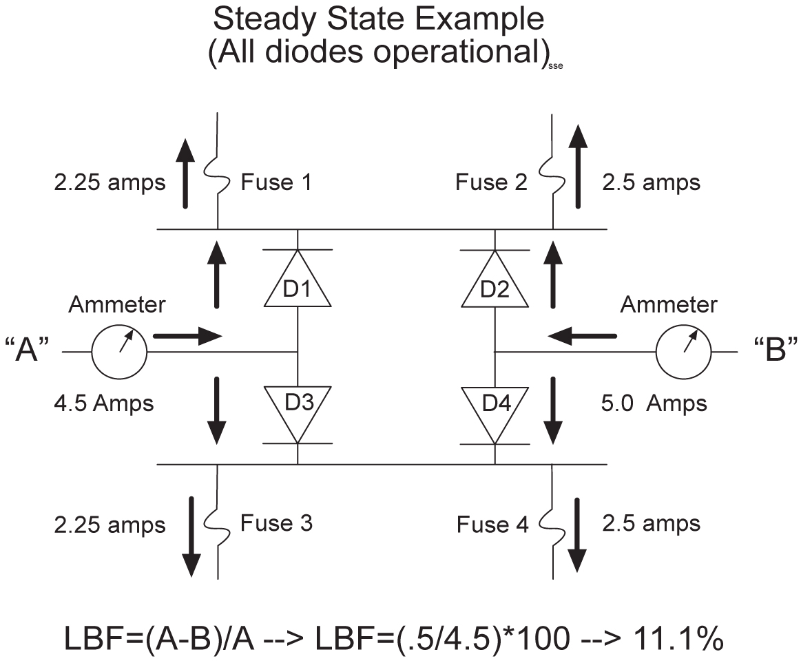
Figure 2-1 FAP High-Level Block Diagram


img/c_maintaining_the_fuse_and_alarm_panel_maintmanual-fig1.jpg

To assist your FAP maintenance efforts, this section provides information about the FAP unit:

  • The FAP components
  • FAP alarms
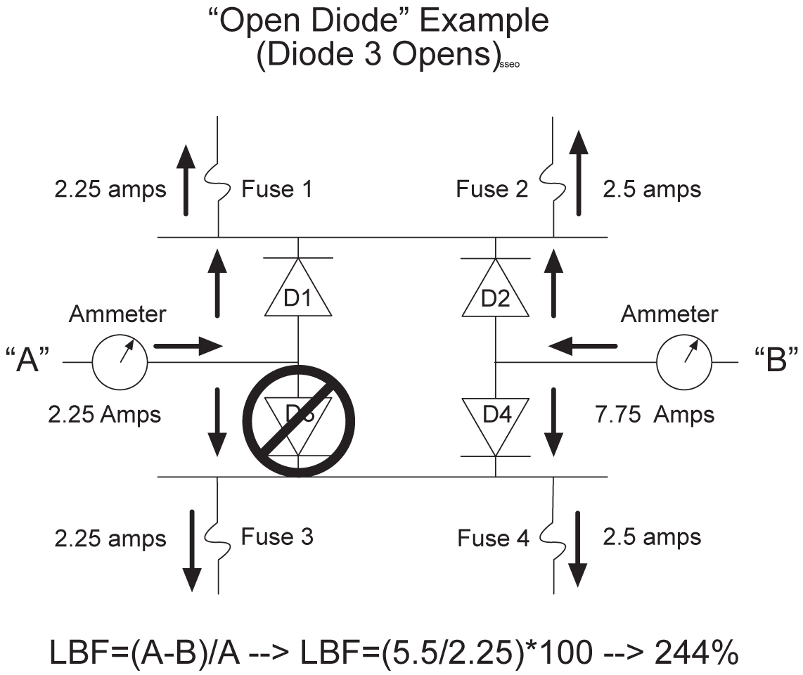
  • Diode testing and the diode jumper

For more detailed information on the FAP and its components, refer to the FAP Technical Reference (820-2888-01).

2.2.1 1U FAP P/N 870-2804-01

The 1U FAP (P/N 870-2804-01) is a low-profile unit that provides protected distribution of –48VDC power to the shelves in the frame. Allowing for the full population of a frame and for the failure of one primary supply, new installations of Control and Extension frames require two 60A feeds.

2.2.1.1 FAP Components

The FAP is composed of three field replaceable units, of which two can be hot-swapped.

Table 2-1 FAP Component Replacement

Component Replacement Requirements Part Number
Diode Board

Field replaceable

870-2806-01

Shorting Board

Field replaceable

870-2805-01

1U FAP

Field replaceable

(with service interruption)

870-2804-01

(includes Diode and Shorting Boards)

Diode Board

The diode board in the FAP contains power diodes and circuitry which allow one bus to pick up the entire load when there is a loss of input power on the other bus.

Shorting Board

The Shorting board allows the removal of the diode board without taking down the system. This permits periodic maintenance of the diodes without having to power down or remove the unit from the shelf. In the bypass position, both A and B power is connected to the fuse blocks so the diode board can be safely removed. The Shorting board has an LED which is off when the board is in normal operational mode and is green when in the bypass mode of operation.

2.2.1.2 Alarms

The FAP provides visual alarms, by means of a lit LED, for a variety of status alarms.

Table 2-2 FAP Alarm Conditions

Alarm Alarm Condition Remote Indications

Critical LED

• EAGLE command through E5-TDM

E5-MDAL not present and E5-MDAL_P jumper off

Dependent on EAGLE software

Major LED

EAGLE command through E5-TDM

Dependent on EAGLE software

Minor LED

EAGLE command through E5-TDM

Dependent on EAGLE software

Fuse LED

• Distribution fuse blown

Alarm circuit board removed (no LED indication)

• Jumper on the jumper circuit board is on

• Power feed failure

Fuse alarm to EAGLE through E5-TDM

PWR A LED

Power feed A is off, but power is available to B.

Fuse alarm to EAGLE through E5-TDM

PWR B LED

Power feed B is off, but power is available to A.

Fuse alarm to EAGLE through E5-TDM

Shorting Board LED

Shorting board in maintenance mode.

Fuse alarm to EAGLE through E5-TDM

A fuse alarm identifies the following problems or conditions within the FAP:

  • blown fuse(s)

  • power loss for side A or B

  • alarm card removed

  • maintenance mode

Use the following indicators to determine the nature of the problem:

Table 2-3 Additional Alarm Indicators

Indicator Alarm Condition

Fuse alarm and fuse flag down

Blown fuse

Fuse alarm and PWR A LED

Input power loss on A

Fuse alarm and PWR B LED

Input power loss on B

Fuse alarm red and Shorting Board LED is green

Shorting Board in maintenance mode (by-passing diodes)

Fuse alarm red and Shorting Board LED is off

Shorting Board in normal mode, blown fuse

2.2.1.3 Diode Testing and the Shorting Board

The Diode Board must be tested periodically. To test the Diode Board without powering down the entire EAGLE, peform the following procedures.

2.2.1.3.1 Maintenance Mode

This section describes how to place the Shorting Board into maintenance (bypass) mode. Maintenance mode allows the removal of the Diode Board without taking down the system.

Procedure — Shorting Board Maintenance Mode

  1. Check to verify the Shorting Board LED is not on, indicating the FAP is in normal mode.2.

  2. Locate two screws securing the Shorting Board in its slot (see Figure 2-2). Note the orientation of the Shorting Board LED. Turn the screws at each corner of the board to the left until they disengage.

    Figure 2-2 Shorting Board Faceplate, Normal Mode


    img/c_jumper_board_1u_sbops_mode_im-fig1.jpg

  3. Pull the board straight out of the FAP until the board is clear of the frame.

  4. Turn the Shorting Board over and reinsert the board into its slot. Note the orientation of the Shorting Board LED (see Figure 2-3).

    Figure 2-3 Shorting Board Faceplate, Maintenance Mode


    img/c_jumper_board_1u_sbmtc_mode_im-fig1.jpg

    The Shorting Board LED turns green and the fuse alarm LEDs turn red.

  5. Ensure the board is seated properly and tighten the two screws to secure the board.

  6. The Shorting Board is now in the maintenance (bypass) mode of operation.

2.2.1.3.2 Diode Board

This section describes how to remove and test the Diode Board.

Procedure — Remove the Diode Board

Use this procedure to remove the Diode Board for diode testing.

  1. Check to verify the Shorting Board LED is on, indicating the FAP is in maintenance (bypass) mode.

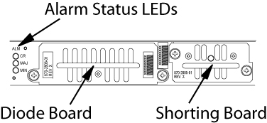
  2. Locate two screws securing the Diode Board in its slot. Turn the screws to the left until they disengage.

    Figure 2-4 Diode Board Faceplate

    img/c_1ufap_diode_board_location_maintmanual.jpg

  3. Pull the board straight out of the FAP until the board is clear of the frame.

Procedure - Diode Testing

Use this procedure to test the power diodes on the Diode Board. A Digital Volt/Ohm Meter (DVM) with a Diode Setting is required. All testing is performed at the edge connector (J1) on the board.

Figure 2-5 Diode Board Edge Connector J1


img/c_1ufap_location_j1_maintmanual.jpg

  1. Set the DVM to test diodes.
  2. Connect the DVM positive (+) lead and negative (-) lead to the pins indicated for each power diode.

    Table 2-4 Power Diode Test Points

    Diode J1 Pin Positive (+) Lead J1 Pin Negative (-) Lead

    CR1 #1

    3

    16

    CR1 #2

    6

    16

    CR2 #1

    14

    1

    CR2 #2

    11

    1

    CR3 #1

    4

    16

    CR3 #2

    5

    16

    CR4 #1

    13

    1

    CR4 #2

    12

    1

    The DVM should indicate a short circuit (>0.1V, <0.2V). Record the measurement.

  3. Reverse the leads.

    The DVM should indicate an open circuit (OL). Record the measurement.

  4. If any measurements are in error, the diode board must be replaced.
  5. If the measurements are within acceptable parameters, reinstall the Diode Board.
2.2.1.3.3 Normal Mode

Use this procedure to place the Shorting board into normal mode. This mode of operation allows one bus to pick up the entire load when there is a loss of input power on the other bus.

Procedure — Shorting Board Normal Mode

  1. Check to verify the Shorting Board LED is green, indicating the FAP is in maintenance mode.

  2. Locate two screws securing the Shorting Board in its slot. Note the orientation of the Shorting Board LED (Figure 2-6). Turn the screws at each corner of the board to the left until they disengage.

    Figure 2-6 Shorting Board Faceplate, Maintenance Mode


    img/c_jumper_board_1u_sbmtc_mode_im-fig1.jpg

  3. Pull the board straight out of the FAP until the board is clear of the frame.

  4. Turn the Shorting Board over and reinsert the board into its slot. Note the orientation of the Shorting Board LED (see Figure 2-7).

    Figure 2-7 Shorting Board Faceplate, Normal Mode


    img/c_jumper_board_1u_sbops_mode_im-fig1.jpg

    Note:

    The Shorting Board LED is off and the fuse alarm LEDs turn green.
  5. Ensure the board is seated properly and tighten the two screws to secure the board.

  6. The Shorting Board is now in the normal mode of operation.

2.2.2 3U FAP

The 3U FAP is a normal-profile unit that provides protected distribution of –48VDC power to the shelves in the frame. Allowing for the full population of a frame and for the failure of one primary supply, new installations of Control and Extension frames require two 60A feeds. The 3U FAP may be one of the following:

  • 870-1606-01 (all revisions)
  • 870-1616-02 with a revision G or lower
  • 870-2320-01 with a revision B or lower
2.2.2.1 FAP Components

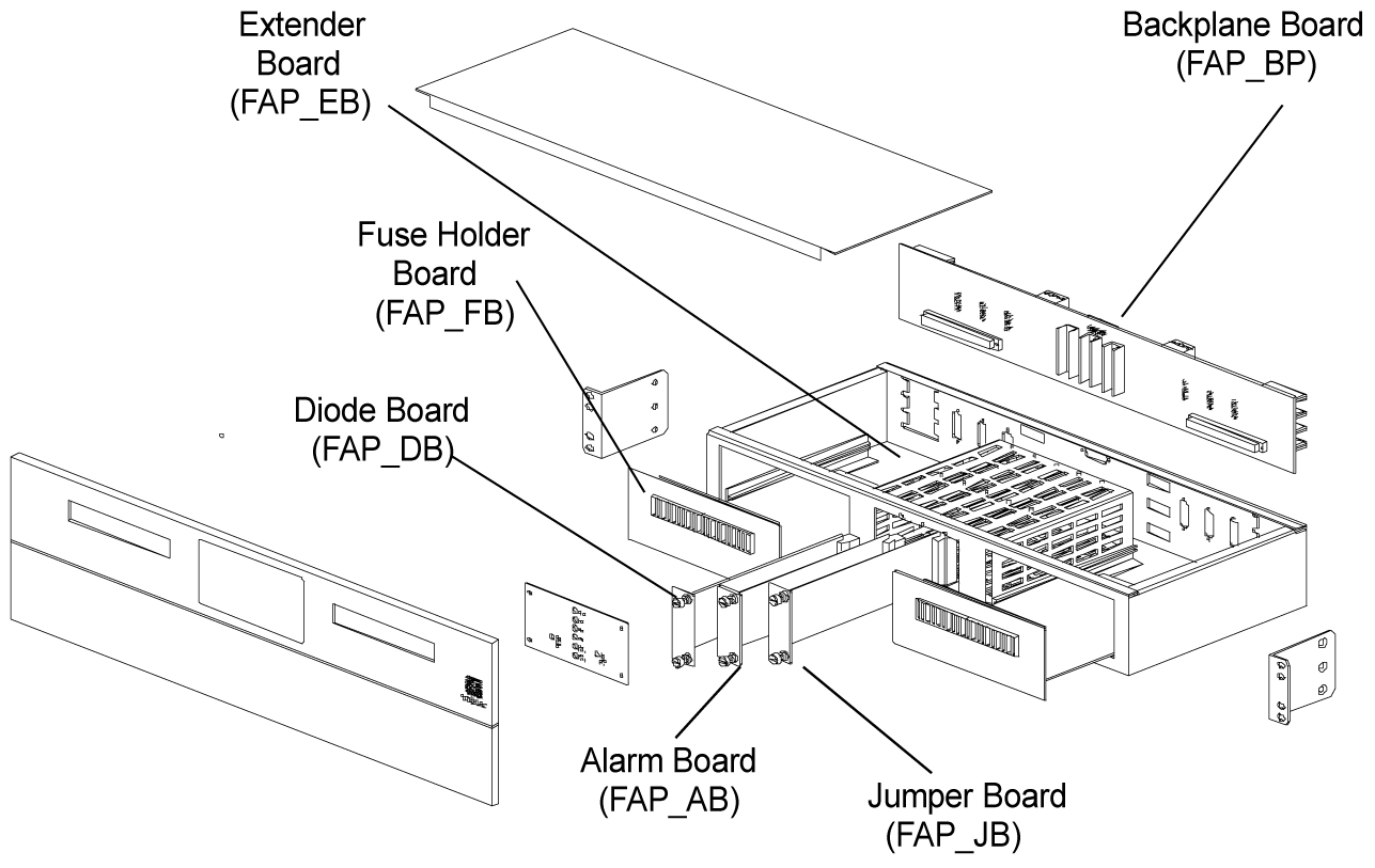
The FAP consists of nine printed circuit boards, each identified by an acronym on its label (see Figure 2-8):

  • Backplane (FAP_BP): Located inside the FAP unit, parallel to the back side of the FAP box.

  • Alarm board (FAP_AB): Located on the center-right of the front panel, set vertically inside the FAP unit, perpendicular to the front panel.

  • Diode boards (FAP_DB): Two boards located on the front panel, flanking the Alarm and Jumper boards on the left and right, and perpendicular to the front panel. Set vertically inside the FAP unit.

  • Extender boards (FAB-EB): Two boards located inside the FAP unit, parallel to the bottom of the FAP box, on the far right and left of the unit.

  • Fuse holder boards (FAP_FB): Two boards located inside and parallel to the front panel, on the far right and left of the FAP unit.

  • Jumper board (FAP_JB): Located on the center-left of the front panel, set vertically in the unit, perpendicular to the front panel.

Figure 2-8 Location of FAP Components

img/c_fap_components_maintmanual-fig1.jpg

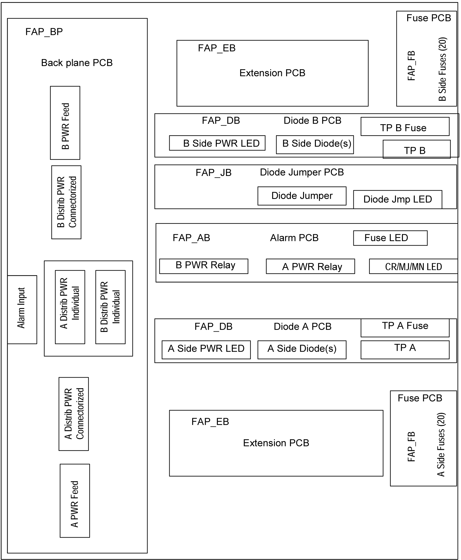
Each of the FAP components has associated functions.

Figure 2-9 FAP Component Functions

img/c_fap_components_maintmanual-fig2.jpg

The FAP is composed of nine circuit boards. Eight of these circuit boards are field replaceable, and can be hot-swapped.

Table 2-5 FAP Component Replacement

Component Replacement Requirements Part Number

FAP Backplane

(FAP_BP)

Must be replaced through factory

850-0515-xx

FAPAlarm Board

(FAP_AB)

Field replaceable

850-0518-xx (card)

870-1609-xx (assembly)

FAP Diode Boards

(FAP_DB_A and

FAP_DB_B)

Field replaceable

(one at a time)

850-0517-xx (card)

870-1608-xx (assembly)

FAP Extender Boards

(FAP_EB)

Field replaceable

(one at a time

with service interruption)

850-0519-xx

FAP Fuse Holder Boards

(FAP_FB)

Field replaceable

(one at a time

with service interruption)

850-0516-xx

FAP Jumper Board

(FAP_JB)

Field replaceable

850-0523-xx (card)

870-1641-xx (assembly)

The following sections describe each type of circuit board:

Backplane Board (FAP_BP)

The backplane circuit board provides all of the external connections for the FAP. It consists primarily of circuit routing and connectors, but also has one pull-down resistor, which provides a default alarm signal for the Fuse Alarm in the event the alarm board is removed from the FAP.

Alarm Board (FAP_AB)

The alarm circuit board provides indicators and relays for the EAGLE status and fuse alarms. This board includes a jumper (JMP50) for future use. This jumper is installed for all existing configurations.

Diode Boards (FAP_DB)

The diode circuit boards provide power diodes and power input test points. Four diode footprints are included: two for Assembly A and two for Assembly B. Only one of the four positions is intended to be populated; the second footprint is provided for future part rating changes or additional heat-dissipation capabilities.

Extender Boards (FAP_EB)

The extender board provides connection between the backpanel board and the fuse holder boards.

Fuse Holder Boards (FAP_FB)

The fuse holder boards provide 20 fuses with a common alarm.

Jumper Board (FAP_JB)

The jumper board provides the capability to by-pass the diode boards with a fuse. Use this board only for maintenance operations.

2.2.2.2 Alarms

The FAP provides visual alarms, by means of a lit LED, for a variety of status alarms (see Table 2-6).

Table 2-6 FAP Alarm Conditions

Alarm Alarm Condition Remote Indications

Critical LED

• EAGLE command through E5-MCAP

E5-MDAL not present and E5-MDAL_P jumper off

Dependent on EAGLE software

Major LED

EAGLE command through E5-MCAP

Dependent on EAGLE software

Minor LED

EAGLE command through E5-MCAP

Dependent on EAGLE software

Fuse LED

• Distribution fuse blown

Alarm circuit board removed (no LED indication)

• Jumper on the jumper circuit board is on

• Power feed failure

Fuse alarm to EAGLE through E5-MCAP

PWR A LED

Power feed A is off, but power is available to B.

Fuse alarm to EAGLE through E5-MCAP

PWR B LED

Power feed B is off, but power is available to A.

Fuse alarm to EAGLE through E5-MCAP

OP/MAINTLED

Jumper on the jumper circuit board is on.

Fuse alarm to EAGLE through E5-MCAP

A fuse alarm identifies the following problems or conditions within the FAP:

  • blown fuse(s)

  • power loss for side A or B

  • alarm card removed

  • maintenance mode

Use the following indicators to determine the nature of the problem:

Table 2-7 Additional Alarm Indicators

Indicator Alarm Condition

Fuse alarm and fuse flag down

Blown fuse

Fuse alarm and PWR A LED

Input power loss on A

Fuse alarm and PWR B LED

Input power loss on B

Fuse alarm and OP/MAINT LED is red

Diode jumper is installed (by-passing diodes)

2.2.2.3 Diode Testing and the Diode Jumper

The diode board must be tested periodically. To test a diode circuit board without powering down the entire EAGLE, perform the procedure listed in Table 2-8 for the corresponding FAP part number.

Table 2-8 FAP Part Numbers and Corresponding Procedures

Part Number FAP Procedure

870-1606-01 (all revisions)

Procedure 1

870-1616-02 revision G or lower

Procedure 1

870-1606-02 revision H or higher

Procedure 2

870-2320-01 revision B or lower

Procedure 1

870-2320-01 revision C or higher

(or 870-2320-03)

Procedure 2

Procedure 1

This procedure to test a diode circuit board without powering down the entire EAGLE applies to the following FAPs:

  • 870-1606-01 (all revisions)

  • 870-1616-02 with a revision G or lower

  • 870-2320-01 with a revision B or lower

  1. Check to verify the OP/MAINT LED is green, indicating the FAP is not in maintenance mode.

  2. Unscrew the two thumbscrews securing the FAP jumper board and remove the board.

  3. On the jumper circuit board, move the jumper (the DB-26 male connector) from P71 to P72. Tighten the thumbscrews connecting the jumper to its mate, to ensure a good connection. This repositioning overrides the diodes, establishing a direct connection between input and fuse panels.

    warning:

    If fuses are blown, DO NOT continue with this procedure. Instead, contact My Oracle Support (MOS) at the appropriate number.
  4. Make sure the glass fuses are installed and verify they are “good” by using the multimeter to check for continuity across each of the glass fuses.

  5. Verify that two glass fuses are behind the P72 connector. If these fuses are not present, install them before continuing.

  6. Slide the jumper board back into the FAP and verify both of the following alarms display:

    • the OP/MAINT LED lights red on the FAP

    • an EAGLE fuse alarm displays on the terminal

      You may now remove either or both diode circuit boards without affecting EAGLE service.

    Note:

    Using the jumper override negates the backpower protection usually provided by the diode board.
  7. Locate diode board A and unscrew the two thumbscrews securing the board. Remove the board from the FAP.

  8. Locate the diode to be tested. It has three pins and is attached to the large heat sink. The diode is labeled CR43.

  9. Set your digital multimeter to measure resistance.

  10. Measure the resistance between the center pin of the diode and either of the outside pins. Record this measurement.

  11. Measure the resistance between these same pins again, but switch the multimeter leads, so the positive lead is now on the opposite pin. Record this measurement.

  12. Compare the two measurements. If the diode is functioning properly, one reading should be less than 10K ohms and the other should be much greater.

    If both readings are above or below 10K ohms, the diode may have failed. Replace the failed board with a spare diode board.

  13. Repeat steps 9 through 11, measuring the resistance between the other outside pin and the center pin.

    This completes the test for diode board A.

  14. Repeat steps 6 through 12, using diode board B. This completes the test for diode board B.

  15. Reinsert the two functional diode boards. Tighten the thumbscrews on each board to secure it to the FAP.

  16. Unscrew the two thumbscrews securing the FAP jumper board and remove the board.

  17. On the jumper circuit board, move the jumper (the DB-26 male connector) back from P72 to its original position on P71. Tighten the thumbscrews connecting the jumper to its mate, to ensure a good connection. This repositioning returns the diodes to their original, non-maintenance position.

  18. Slide the jumper board back into the FAP. Verify the OP/MAINT LED lights green. The fuse alarm LED returns to green.

    The diode board testing procedure is completed.

Procedure 2

This procedure to test a diode circuit board without powering down the entire EAGLE applies to the following FAPs:

  • 870-1606-02 with revision H or higher

  • 870-2320-01 with revision C or higher (or 870-2320-03)

  1. Check to verify the OP/MAINTLED is green, indicating the FAP is not in maintenance mode.
  2. Unscrew the two thumbscrews securing the FAP jumper board and remove the board.
  3. On the jumper circuit board, unclip the 12 pin connector jumper from P71 and re-attach it to P72.
    Insert it until the plastic retaining clips "snap". Note that the jumper has a retaining strap so it won't get dropped or lost. This repositioning overrides the diodes, establishing a direct connection between input and fuse panels.

    warning:

    If fuses are blown, DO NOT continue with this procedure. Instead, contact My Oracle Support (MOS) at the appropriate number.
  4. Slide the jumper board back into the FAP and verify both of the following alarms display:
    • the OP/MAINTLED lights red on the FAP
    • an EAGLE fuse alarm displays on the terminal

      You may now remove either or both diode circuit boards without affecting EAGLE service.

  5. Locate diode board A and unscrew the two thumbscrews securing the board.
    Remove the board from the FAP.
  6. Locate the diode to be tested.
    There are two power diodes, each with three pins. They are labeled CR43 and CR44 for diode board A.
  7. Set your digital multimeter to diode check mode..
  8. Measure the voltage drop between the center pin of the CR43 diode and either of the outside pins with the ground probe on the center lead.
    Record this measurement.
  9. Measure the voltage drop between these same pins again, but switch the multimeter leads, so the positive lead is now on the opposite pin.
    Record this measurement.
  10. Compare the two measurements.
    If the diode is functioning properly, the first reading should be between 0.2 and 0.1 volts and the other should be read as an open circuit. Otherwise, replace2 the failed board with a spare diode board.
  11. Repeat 9 through 10, measuring the voltage between the other outside pin and the center pin of CR43.
  12. Repeat 6 through 10, using diode board B.
    This completes the test for diode board B.
  13. Reinsert the two functional diode boards.
    Tighten the thumbscrews on each board to secure it to the FAP.
  14. Unscrew the two thumbscrews securing the FAP jumper board and remove the board.
  15. On the jumper circuit board, unclip the 12 pin connector jumper back from P72 to its original position on P71.
    Insert it until the plastic retaining clips “snap.” This repositioning returns the diodes to their original, non-maintenance position.
  16. Slide the jumper board back into the FAP.
    Verify the OP/MAINTLED lights green. The fuse alarm LED returns to green. The diode board testing procedure is completed.

2.3 Removable Drives

This section provides information about the removable drives associated with the EAGLE Maintenance Administration Subsystem Processor (MASP).

A removable drive is used for two purposes:

  • To hold an off-line, backup copy of the administered data and system GPLs

  • To hold a copy of the measurement tables

To use a removable drive to hold the system data, it must be formatted for system data. To use a removable drive to hold measurements data, it must be formatted for measurements data. The EAGLE provides the user the ability to format a removable drive for either of these purposes. A removable drive can be formatted on the EAGLE by using the format-disk command. For more information on the format-disk command refer to Commands User's Guide.

Removable drives described in this section include:

The USB storage media in the flush-mounted USB port of the MSP card is also used for backups. The dest=usb parameter is used to run the same.

2.3.1 Removable USB Drive

Purpose:
This section is referenced in this manual by many procedures requiring the use of the removable USB thumb disk in the E5-MASP card. The procedures found in this section are recommended procedures for handling the removable USB drive in the E5-MASP card.
Requirements:
None

Procedure - Remove USB Drive

  1. Verify that the removable USB drive is locked in position and in use.

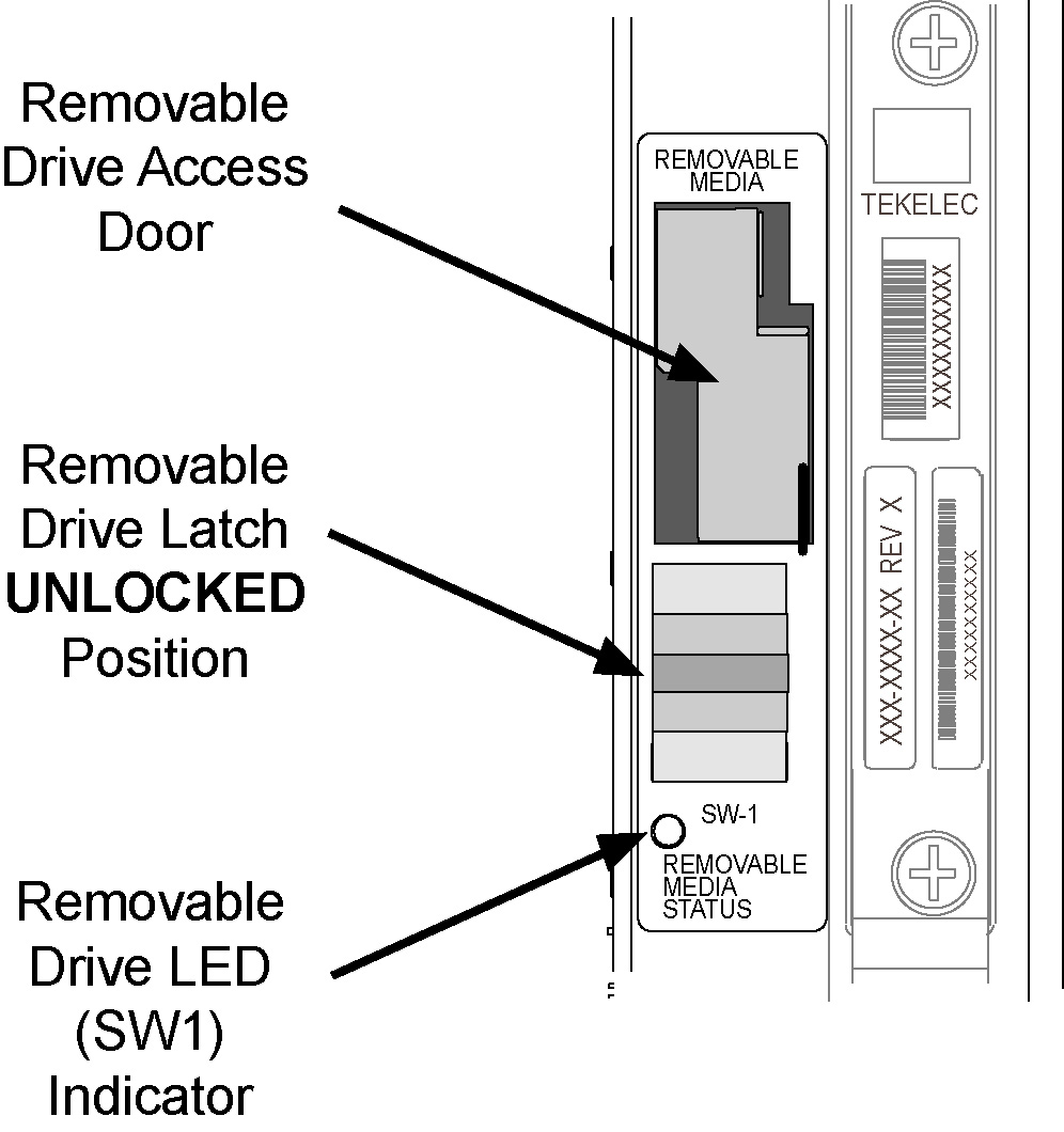
    The removable drive latch (SW1) is in the LOCKED position and the Removable Media Status LED on the E5-MASP is Off. Refer to Figure 2-10.

    Figure 2-10 Removable USB Drive LOCKED

    img/870-2903-xx_e5-masp_removable_drive_latch_locked.jpg
  2. Move SW1 from the LOCKED to the unlocked position and wait for the LED to indicate a steady blue state. See Figure 2-11.

    When SW1 is transitioned from locked to unlocked, the LED will flash blue to indicate the drive is unlocked and in process of shutting down.

    Caution:

    Removal of the drive prior to the LED indicating steady blue could result in drive corruption.

    Figure 2-11 Removable USB Drive UNLOCKED

    img/870-2903-xx_e5-masp_removable_drive_latch_unlocked.jpg
  3. When the LED indicates a steady blue state, the removable USB drive can be safely removed. The LED is off when the USB drive is fully ejected from the drive media.
    The USB drive can now be removed from the drive media.
  4. Lift the access door up, swing it past the detent position so that the door remains open on its own.
  5. Grasp the pull tab of the slide and pull the slide out slowly until it stops (it travels about a half inch).

    Caution:

    The full travel of the slide is less than an inch, do not try to pull the assembly to expose the full length of the thumb drive as this is beyond the slide’s designed travel.
  6. The USB drive is disengaged and can be taken from the inject eject assembly.
  7. Insert a USB drive into the inject-eject assembly.
  8. Grasp the pull tab of the slide and push the slide in slowly until you feel the USB drive is seated in its slot (it travels about a half inch).
  9. Close the access door.
  10. Move SW1 from the unlocked to the LOCKED position.

    When SW1 is transitioned from unlocked to locked, the LED will flash blue to indicate the drive is locked and in process of coming online.

  11. When the LED turns Off, the removable USB drive is ready for use.

2.3.2 Fixed SATA Drive

Purpose:
This section is referenced in this user's guide by many procedures requiring the use of the fixed SATA drive in the E5-MASP card. The procedures found in this section are recommended procedures for handling the fixed drive in the E5-MASP card.
Requirements
  • The new SATA Drives to be installed should be at the current system release.
  • Before beginning this procedure, make sure there is a copy of the current release GPLs on a removable USB drive on-hand.
  • System backups should be performed prior to the start of this procedure. Refer to Daily Procedures.
  • You must be logged in to the EAGLE prior to performing this procedure.

Procedure - Remove Fixed SATA Drive

  1. Enter the following command to verify that the Measurement feature bit is on.
    rtrv-feat
    The following is an example of a possible output. The MEASPLAT field shows whether the Measurement feature is on or off. In this example, Measurement feature is ON.
        eagle3 02-01-05 00:51:32 EST  EAGLE5 41.2.0-62.69.65
        rtrv-feat
        Command entered at terminal #7.
    ;
    
        eagle3 02-01-05 00:51:32 EST  EAGLE5 41.2.0-62.69.65
        EAGLE FEATURE LIST
    
        GTT      = on      GWS      = on      NRT      = off
        X25G     = off     LAN      = on      CRMD     = off
        SEAS     = off     LFS      = off     MTPRS    = off
        FAN      = on      DSTN5000 = off     WNP      = off
        CNCF     = off     TLNP     = off     SCCPCNV  = off
        TCAPCNV  = off     IPISUP   = off     X252000  = off
        PLNP     = off     NCR      = off     ITUMTPRS = on
        SLSOCB   = off     EGTT     = on      VGTT     = on
        MPC      = on      ITUDUPPC = on      MEASPLAT = on
        TSCSYNC  = off     E5IS     = off
    ;
    If feature bit is turned OFF, go to 5.
  2. Enter the following command to retrieve the measurements setup.
    rtrv-meas-sched
    The following is an example of a possible output. The COLLECT field shows whether measurement collection is on or off. In this example, measurement collection isON.
        npeeagle4 02-02-04 21:13:49 EST  EAGLE5 41.2.0-62.69.65
        rtrv-meas-sched
        Command entered at terminal #1.
    ;
    
        npeeagle4 02-02-04 21:13:49 EST  EAGLE5 41.2.0-62.69.65
        COLLECT        = ON
        GTWYLSFLTR     = (both)
        ---------------------
        SYSTOT-STP     = (off)
        SYSTOT-TT      = (off)
        COMP-LNKSET    = (off)
        COMP-LINK      = (off)
        GTWY-STP       = (off)
        GTWY-LNKSET    = (off)
        MTCD-STP       = (on)
        MTCD-LINK      = (on)
        MTCD-LNKSET    = (on)
    
    ;
    If measurement collection is OFF, go to 5.
  3. Issue the following command to turn OFF measurement collection.
    chg-meas:collect=off
    The following is an example of a possible output.
        tekelecstp YY-MM-DD hh:mm:ss TTTT PPP  XX.x.x-YY.y.y
        chg-meas:collect=off
        Command entered at terminal #10.
    ;
        tekelecstp YY-MM-DD hh:mm:ss TTTT PPP  XX.x.x-YY.y.y
        CHG-MEAS: MASP A – COMPLTD
    ;
  4. Enter the following command to verify measurements collection is OFF.
    rtrv-meas-sched
    The following is an example of a possible output. The COLLECT field shows whether measurement collection is on or off. In this example, measurement collection is OFF.
        npeeagle4 02-02-04 21:13:49 EST  EAGLE5 41.2.0-62.69.65
        rtrv-meas-sched
        Command entered at terminal #1.
    ;
    
        npeeagle4 02-02-04 21:13:49 EST  EAGLE5 41.2.0-62.69.65
        COLLECT        = OFF
        GTWYLSFLTR     = (both)
        ---------------------
        SYSTOT-STP     = (off)
        SYSTOT-TT      = (off)
        COMP-LNKSET    = (off)
        COMP-LINK      = (off)
        GTWY-STP       = (off)
        GTWY-LNKSET    = (off)
        MTCD-STP       = (on)
        MTCD-LINK      = (on)
        MTCD-LNKSET    = (on)
    
    ;
  5. Enter the following command to display the card status:
    rept-stat-card:appl=oam

    The following is an example of a possible output.

    Command Accepted - Processing
    
        tekelecstp YY-MM-DD hh:mm:ss TTTT PPP  XX.x.x-YY.y.y
        rept-stat-card:appl=oam
        Command entered at terminal #14.
    ;
    
        tekelecstp 10-04-19 16:47:51 EDT  EAGLE5 41.1.0-62.64.1
        CARD   VERSION      TYPE      GPL        PST            SST        AST
        1113   132-064-000  E5MCAP    OAMHC      IS-NR          Standby    -----
        1115   132-064-000  E5MCAP    OAMHC      IS-NR          Active     -----
    
        Command Completed.
    ;
  6. Enter the following command to display the card status:
    this rept-stat-card

    The following is an example of a possible output.

    
        e5oam 08-12-01 15:38:32 EST  EAGLE 46.0.0
        CARD   VERSION      TYPE      GPL        PST            SST        AST
        1108   -----------  MCPM      MCP        OOS-MT-DSBLD   Manual     -----
        1109   030-009-000  HIPR2     HIPR2       IS-NR          Active     -----
        1110   030-009-000  HIPR2     HIPR2       IS-NR          Active     -----
        1111   030-010-000  IPSM      IPS        IS-NR          Active     -----
        1113   030-010-008  E5MCAP    OAMHC      IS-NR          Standby    -----
        1114   -----------  E5TDM                IS-NR          Active     -----
        1115   030-010-008  E5MCAP    OAMHC      IS-NR          Active     -----
        1116   -----------  E5TDM                IS-NR          Active     -----
        1117   -----------  E5MDAL               OOS-MT         Isolated   -----
    
        Command Completed.

    In this sample output, 1113/1114 are standby and 1115/1116 are active.

    Verify the E5-MASP card containing the fixed SATA drive to be replaced is in the Standby position before continuing.
    • If it is Standby, go to 10.
    • If it is not Standby, go to 7.
  7. Enter the following command to force the Active E5-MASP card to become Standby
    init-card:loc=xxxx

    where xxxx is the card location (1113 or 1115).

    Note:

    User will need to login after executing this command.
  8. Enter the following command to re-login:
    login:uid=eagle
  9. Enter the password to complete login:
    Enter Password : xxxxx

    Note:

    This document does not provide the passwords required in the procedures. Passwords should be acquired from the customer.
    The following is an example of a possible output.
    Command Accepted - Processing
    
        tekelecstp YY-MM-DD hh:mm:ss TTTT PPP  XX.x.x-YY.y.y    
        Command entered at terminal #13.
    ;
        tekelecstp YY-MM-DD hh:mm:ss TTTT PPP  XX.x.x-YY.y.y
        NOTICE: This is a private computer system.
        Unauthorized access or use may lead to prosecution.
        0 LOGIN failures since last successful LOGIN
        Last successful LOGIN was on port 13 on 09-03-04 @ 14:18:21
    
    ;
  10. Inhibit the Standby card location from service by entering the following command:
    inh-card:loc=xxxx

    wherexxxx is the Standby card location.

    The following is an example of a possible output.
    Command Accepted - Processing
    
        eagle3 02-01-18 18:00:06 EST  EAGLE 41.2.0-62.69.65
        inh-card:loc=1113
        Command entered at terminal #1.
    ;
    
        eagle3 02-01-18 18:00:06 EST  EAGLE 41.2.0-62.69.65
        Card has been inhibited.
    ;
    
        eagle3 02-01-18 18:00:06 EST  EAGLE 41.2.0-62.69.65
        Command Completed.
    ;
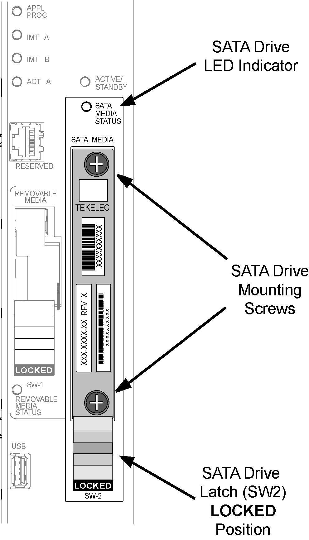
  11. Verify that the SATA drive is locked in position and in use. Refer to Figure 2-12.

    The SATA drive latch (SW2) is in the LOCKED position and the SATA Media Status LED on the E5-MASP is Off.

    Figure 2-12 SATA Drive Locked

    img/870-2903-xx_e5-masp_sata_drive_latch_locked.jpg
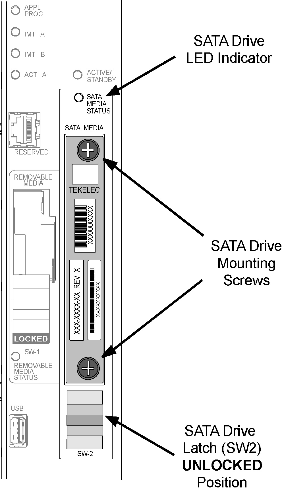
  12. Move SW2 from the LOCKED to the unlocked position and wait for the LED to indicate a steady blue state. See Figure 2-13.

    When SW2 is transitioned from locked to unlocked, the LED will flash blue to indicate the drive is unlocked and in process of shutting down.

    Caution:

    Removal of the drive prior to the LED indicating steady red could result in drive corruption.

    Caution:

    If locking switch is transitioned from locked to unlocked and the E5-MASP is in service, removal of the drive module will result in a card obit. All drive LEDs will blink red.

    Figure 2-13 SATA Drive UNLOCKED

    img/870-2903-xx_e5-masp_sata_drive_latch_unlocked.jpg
  13. When the LED indicates a steady blue state, the SATA drive can be safely removed. The LED is off when the drive is fully ejected from the drive.

    The drive can now be removed from the slot.

  14. Loosen the SATA drive mounting screws.
  15. Grasp the screws and pull the drive out slowly until it is free from the card.
  16. Slide a SATA drive into the drive slot on the card.
  17. Gently push the drive in slowly until it is properly seated.
  18. Tighten the mounting screws.
  19. Move SW2 from the unlocked to the LOCKED position.

    When SW2 is transitioned from unlocked to locked, the LED will flash blue to indicate the drive is locked and in process of coming online.

  20. When the LED turns Off, the SATA drive is ready for use.
  21. Enter the following command to verify the card is in Standby and OOS-MT-DSBLD.
    rept-stat-card:loc=xxxx:mode=full

    where xxxx is the card location (1113 or 1115).

    The following is an example of a possible output.
    Command Accepted - Processing
    
        eagle3 02-01-01 00:35:50 EST  EAGLE5 41.2.0-62.69.65
        rept-stat-card:loc=1115:mode=full
        Command entered at terminal #1.
    ;
    
        eagle3 02-01-01 00:35:50 EST  EAGLE5 41.2.0-62.69.65
        CARD   VERSION      TYPE      GPL        PST            SST        AST
        1115   -----------  E5MCAP    OAMHC      OOS-MT-DSBLD   Manual     -----
          ALARM STATUS       = **  0514 Standby MASP is inhibited
          BLMCAP  GPL version = 132-068-000
          IMT BUS A           = -----
          IMT BUS B           = -----
          CLOCK A             = ----
          CLOCK B             = ----
          CLOCK I             = ----
          MBD BIP STATUS      = Valid
          MOTHER BOARD ID     = E5-MCAP
          DBD STATUS          = Valid
          DBD TYPE            = 1G ENET
          DBD MEMORY SIZE     = 4096M
          HW VERIFICATION CODE = ----
          CURRENT TEMPERATURE   =  29C ( 85F)
          PEAK TEMPERATURE:     =  29C ( 85F)     [02-01-01 00:23]
          TROUBLE TEXT VER.   = ----
    
        Command Completed.
    ;
  22. Issue the command to retrieve GPL versions.
    rept-stat-gpl:loc=<stby E5-MASP>

    where <stby E5-MASP> is the card location (1113 or 1115).

    The following is an example of a possible output.
    Command Accepted - Processing
    
        eagle3 02-01-01 00:36:25 EST  EAGLE5 41.2.0-62.69.65
        rept-stat-gpl:loc=1115
        Command entered at terminal #1.
    ;
    
        eagle3 02-01-01 00:36:25 EST  EAGLE5 41.2.0-62.69.65
        GPL Auditing  ON
    
        GPL        CARD      RUNNING            APPROVED      TRIAL
        OAMHC      1115      -----------        132-069-061   132-069-061  *
               BLMCAP        132-068-000        132-068-000   132-068-000
    
        Command Completed.
    ;

    Verify that the OAMHC and BLMCAP GPLs match on the Running, Approved and Trial columns.

    Note:

    If GPL are in alarm contact My Oracle Support (MOS) and have system USB drives available for corrections
  23. Enter the following command to put the card that was inhibited in back into service.
    alw-card:loc=xxxx

    wherexxxx is the card location used in 6.

    Following is an example of a possible output.
    Command Accepted - Processing
    
        eagle3 02-01-18 18:02:20 EST  EAGLE5 41.2.0-62.69.65
        alw-card:loc=1113
        Command entered at terminal #1.
    ;
    
        eagle3 02-01-18 18:02:20 EST  EAGLE5 41.2.0-62.69.65
        Card has been allowed.
    ;
    
        eagle3 02-01-18 18:02:20 EST  EAGLE5 41.2.0-62.69.65
        Command Completed.
    ;

    Note:

    Allow the card to run for 5 minutes before continuing.
  24. Enter the following command to verify the database is not consistent (different level as the other cards in the system).
    rept-stat-db:display=version
    The following is an example of a possible output.
    Command Accepted - Processing
    
        eagle3 02-01-10 21:52:58 EST  EAGLE5 41.2.0-62.69.65
        rept-stat-db:display=version
        Command entered at terminal #1.
    ;
    
        eagle3 02-01-10 21:52:59 EST  EAGLE5 41.2.0-62.69.65
        DATABASE STATUS: >> OK <<
                E5TDM 1114 ( ACTV )                 E5TDM 1116 ( STDBY)
                C   LEVEL    TIME LAST BACKUP     C   LEVEL    TIME LAST BACKUP
                - -------- ---------------------- - -------- ----------------------
        FD BKUP Y       79 02-01-05 18:06:16 EST  Y        1 02-01-05 00:06:16 EST
        FD CRNT Y       79                        Y        1
                MCAP 1113                         MCAP 1115
                - --------                        - --------
        RD BKUP -    -         -        -         -    -         -        -
        USB BKP -    -         -        -         -    -         -        -
    
        CARD/APPL  LOC   C  T  LEVEL       TIME LAST UPDATE   VERSION STATUS
        ---------  ----  -  -  ----------  -----------------  -------------------
        OAMHC-RMV    1113  -  -      -           -        -          -
        OAMHC-USB    1113  -  -      -           -        -          -
        E5TDM-CRNT   1114  Y  N       79     02-01-04 23:46:18  132-013-000  NORMAL
        E5TDM-BKUP   1114  Y  -       79     02-01-04 23:46:18  132-013-000  NORMAL
        OAMHC-RMV    1115  -  -      -           -        -          -
        E5TDM-CRNT   1116  Y  N        1     02-01-04 00:06:16  132-013-000  NORMAL
        E5TDM-BKUP   1116  Y  -        1     02-01-04 00:06:16  132-013-000  NORMAL
    
                        EPAP A  (NOACCS)
                         C  BIRTHDATE          LEVEL       EXCEPTION
                         -  -----------------  ----------  --------------
        PDB                    -        -          -             -
        RTDB                   -        -          -             -
        RTDB-EAGLE       -     -        -          -             -
    
                        EPAP B  (NOACCS)
                         C  BIRTHDATE          LEVEL       EXCEPTION
                         -  -----------------  ----------  --------------
        PDB                    -        -          -             -
        RTDB                   -        -          -             -
        RTDB-EAGLE       -     -        -          -             -
    
    
    ;

    Compare the VERSION STATUS of the E5-MASP cards. The DB Level in the new drive is expected to be different.

    If the database VERSION on the new disk is not the same as the active disk, stop the procedure and contact My Oracle Support (MOS).

  25. Enter the following command to show the version numbers of the GPLs stored on each fixed disk (E5-MASP).
    rtrv-gpl
    The following is an example of a possible output.
        tekelecstp 18-01-18 21:23:11 EST  EAGLE 46.5.1.5.0-73.10.0
        rtrv-gpl
        Command entered at terminal #18.
    ;
    
    Command Accepted - Processing
        tekelecstp 18-01-18 21:23:11 EST  EAGLE 46.5.1.5.0-73.10.0
        GPL Auditing  ON
    
        GPL       CARD  RELEASE      APPROVED         TRIAL        REMOVE TRIAL
        OAMHC     1114  143-010-000  143-010-000 ALM  -----------  -----------
        OAMHC     1116  143-010-000  143-010-000 ALM  -----------  -----------
        OAMHC     1115  -----------  -----------      -----------  -----------
        OAMHC69   1114  143-010-000  143-010-000 ALM  -----------  -----------
        OAMHC69   1116  143-010-000  143-010-000 ALM  -----------  -----------
        OAMHC69   1115  -----------  -----------      -----------  -----------
        IPSG32    1114  143-010-000  143-010-000      143-010-000  -----------
        IPSG32    1116  143-010-000  143-010-000      143-010-000  -----------
        IPSG32    1115  -----------  -----------      -----------  -----------
        BLMCAP    1114  143-010-000  143-010-000      143-010-000  -----------
        BLMCAP    1116  143-010-000  143-010-000      143-010-000  -----------
        BLMCAP    1115  -----------  -----------      -----------  -----------
        HIPR2     1114  143-010-000  143-010-000      143-010-000  -----------
        HIPR2     1116  143-010-000  143-010-000      143-010-000  -----------
        HIPR2     1115  -----------  -----------      -----------  -----------
        SFAPP     1114  143-010-000  143-010-000 ALM  143-010-000  -----------
        SFAPP     1116  143-010-000  143-010-000 ALM  143-010-000  -----------
        SFAPP     1115  -----------  -----------      -----------  -----------
        SS7HC     1114  143-010-000  143-010-000      143-010-000  -----------
        SS7HC     1116  143-010-000  143-010-000      143-010-000  -----------
        SS7HC     1115  -----------  -----------      -----------  -----------
        SCCPHC    1114  143-010-000  143-010-000      143-010-000  -----------
        SCCPHC    1116  143-010-000  143-010-000      143-010-000  -----------
        SCCPHC    1115  -----------  -----------      -----------  -----------
        ERTHC     1114  143-010-000  143-010-000      143-010-000  -----------
        ERTHC     1116  143-010-000  143-010-000      143-010-000  -----------
        ERTHC     1115  -----------  -----------      -----------  -----------
        IPSHC     1114  143-010-000  143-010-000      143-010-000  -----------
        IPSHC     1116  143-010-000  143-010-000      143-010-000  -----------
        IPSHC     1115  -----------  -----------      -----------  -----------
        ATMHC     1114  143-010-000  143-010-000      143-010-000  -----------
        ATMHC     1116  143-010-000  143-010-000      143-010-000  -----------
        ATMHC     1115  -----------  -----------      -----------  -----------
        IPSG      1114  143-010-000  143-010-000      143-010-000  -----------
        IPSG      1116  143-010-000  143-010-000      143-010-000  -----------
        IPSG      1115  -----------  -----------      -----------  -----------
        PKTGHC    1114  143-010-000  143-010-000      -----------  -----------
        PKTGHC    1116  143-010-000  143-010-000      -----------  -----------
        PKTGHC    1115  -----------  -----------      -----------  -----------
        BLIXP     1114  143-010-000  143-010-000      143-010-000  -----------
        BLIXP     1116  143-010-000  143-010-000      143-010-000  -----------
        BLIXP     1115  -----------  -----------      -----------  -----------
        MCPHC     1114  143-010-000  143-010-000      143-010-000  -----------
        MCPHC     1116  143-010-000  143-010-000      143-010-000  -----------
        MCPHC     1115  -----------  -----------      -----------  -----------
        SIPHC     1114  143-010-000  143-010-000      143-010-000  -----------
        SIPHC     1116  143-010-000  143-010-000      143-010-000  -----------
        SIPHC     1115  -----------  -----------      -----------  -----------
        DEIRHC    1114  143-010-000  143-010-000      143-010-000  -----------
        DEIRHC    1116  143-010-000  143-010-000      143-010-000  -----------
        DEIRHC    1115  -----------  -----------      -----------  -----------
        ENUMHC    1114  143-010-000  143-010-000      143-010-000  -----------
        ENUMHC    1116  143-010-000  143-010-000      143-010-000  -----------
        ENUMHC    1115  -----------  -----------      -----------  -----------
        PKTG64    1114  143-010-000  143-010-000      -----------  -----------
        PKTG64    1116  143-010-000  143-010-000      -----------  -----------
        PKTG64    1115  -----------  -----------      -----------  -----------
        BLDC64    1114  143-010-000  -----------      143-010-000  -----------
        BLDC64    1116  143-010-000  000-000-000 ALM  143-010-000  -----------
        BLDC64    1115  -----------  -----------      -----------  -----------
        SCCP64    1114  143-010-000  143-010-000      143-010-000  -----------
        SCCP64    1116  143-010-000  143-010-000      143-010-000  -----------
        SCCP64    1115  -----------  -----------      -----------  -----------
        BLSLC32   1114  143-010-000  143-010-000      143-010-000  -----------
        BLSLC32   1116  143-010-000  143-010-000      143-010-000  -----------
        BLSLC32   1115  -----------  -----------      -----------  -----------
        BLSLC64   1114  143-010-000  143-010-000      143-010-000  -----------
        BLSLC64   1116  143-010-000  143-010-000      143-010-000  -----------
        BLSLC64   1115  -----------  -----------      -----------  -----------
        SIP64     1114  143-010-000  143-010-000      143-010-000  -----------
        SIP64     1116  143-010-000  143-010-000      143-010-000  -----------
        SIP64     1115  -----------  -----------      -----------  -----------
        DEIR64    1114  143-010-000  143-010-000      143-010-000  -----------
        DEIR64    1116  143-010-000  143-010-000      143-010-000  -----------
        DEIR64    1115  -----------  -----------      -----------  -----------
        ENUM64    1114  143-010-000  143-010-000      143-010-000  -----------
        ENUM64    1116  143-010-000  143-010-000      143-010-000  -----------
        ENUM64    1115  -----------  -----------      -----------  -----------
        BLDC32    1114  143-010-000  -----------      143-010-000  -----------
        BLDC32    1116  143-010-000  -----------      143-010-000  -----------
        BLDC32    1115  -----------  -----------      -----------  -----------
        MCPHC69   1114  143-010-000  143-010-000      143-010-000  -----------
        MCPHC69   1116  143-010-000  143-010-000      143-010-000  -----------
        MCPHC69   1115  -----------  -----------      -----------  -----------
        IPSHC69   1114  143-010-000  143-010-000      143-010-000  -----------
        IPSHC69   1116  143-010-000  143-010-000      143-010-000  -----------
        IPSHC69   1115  -----------  -----------      -----------  -----------
        BLSL932   1114  143-010-000  143-010-000      143-010-000  -----------
        BLSL932   1116  143-010-000  143-010-000      143-010-000  -----------
        BLSL932   1115  -----------  -----------      -----------  -----------
    
    ;
    Command Executed
    

    If the new SATA drive shows alarmed GPLs, contact My Oracle Support (MOS).

  26. Enter the following command to repair the standby’s E5-MASP database:
    chg-db:action=repair

    The action=repair copies the current and backup databases from the active to the standby fixed disk.

    The following is an example of a possible output.

    
    RLGHNCXA03W 03-08-27 03:46:49 EST  EAGLE 34.0.0
    chg-db:action=repair
    Command entered at terminal #10.
    ;
    RLGHNCXA03W 03-08-27 03:46:50 EST  EAGLE 34.0.0
    REPAIR: MASP A - Repair starts on standby MASP.
    ;

    Note:

    Observe that the command execution time may require approximately 20 to 45 minutes.
    
    RLGHNCXA03W 03-08-27 04:15:22 EST  EAGLE 34.0.0
    REPAIR: MASP A - Repair from fixed disk complete.
    ;

    Wait for the ‘repair complete’ message to display and for the E5-MASP to return to in-service status.

  27. Issue the report status command for the standby E5-MASP.
    rept-stat-card:loc=xxxx:mode=full

    Wherexxxx is the STBY E5-MASP slot from 6.

    The following is an example of a possible output.
        tekelecstp YY-MM-DD hh:mm:ss TTTT PPP  XX.x.x-YY.y.y
        rept-stat-card:loc=xxxx
        Command entered at terminal #10.
    ;
        tekelecstp YY-MM-DD hh:mm:ss TTTT PPP  XX.x.x-YY.y.y
        CARD   VERSION      TYPE      GPL        PST            SST        AST
        xxxx   XXX-XXX-XXX  E5MCAP    OAMHC      IS-NR          Standby    -------
          ALARM STATUS       = No Alarms.
          BLMCAP  GPL version = XXX-XXX-XXX
          IMT BUS A           = Conn
          IMT BUS B           = Conn
          CLOCK A             = Active
          CLOCK B             = Idle
          CLOCK I             = Idle
          MBD BIP STATUS      = Valid
          MOTHER BOARD ID     = E5-MCAP
          DBD STATUS          = Valid
          DBD TYPE            = 1G ENET
          DBD MEMORY SIZE     = 4096M
          HW VERIFICATION CODE = ----
          CURRENT TEMPERATURE   =  44C (112F)
          PEAK TEMPERATURE:     =  46C (115F)     [09-03-31 08:18]
          TROUBLE TEXT VER.   = ----
    
        Command Completed.
    ;

    Verify that the standby goes to IS-NR.

  28. Enter the following command to verify that the database counts of both MASPs.
    rept-stat-db:display=all
    The following is an example of the possible output for a good database.
        eagle3 02-01-11 16:11:25 EST  EAGLE5 41.2.0-62.69.65
        rept-stat-db:display=version
        Command entered at terminal #1.
    ;
    
        eagle3 02-01-11 16:11:26 EST  EAGLE5 41.2.0-62.69.65
        DATABASE STATUS: >> OK <<
                E5TDM 1114 ( ACTV )                 E5TDM 1116 ( STDBY)
                C   LEVEL    TIME LAST BACKUP     C   LEVEL    TIME LAST BACKUP
                - -------- ---------------------- - -------- ----------------------
        FD BKUP Y       79 02-01-05 18:06:16 EST  Y  79 02-01-05 18:06:16 EST
        FD CRNT Y       79                        Y  79
                MCAP 1113                         MCAP 1115
                - --------                        - --------
        RD BKUP Y       79 02-01-05 11:15:16 EST  -    -         -        -
        USB BKP -    -         -        -         -    -         -        -
    
        CARD/APPL  LOC   C  T  LEVEL       TIME LAST UPDATE   VERSION STATUS
        ---------  ----  -  -  ----------  -----------------  -------------------
        OAMHC-RMV    1113  -  -      -           -        -          -
        OAMHC-USB    1113  -  -      -           -        -          -
        E5TDM-CRNT   1114  Y  N     79     02-01-04 23:46:18  132-013-000  NORMAL
        E5TDM-BKUP   1114  Y  -     79     02-01-04 23:46:18  132-013-000  NORMAL
        OAMHC-RMV    1115  -  -      -           -        -          -
        E5TDM-CRNT   1116  Y  N     79     02-01-04 23:46:18  132-013-000  NORMAL
        E5TDM-BKUP   1116  Y  -     79     02-01-04 23:46:18  132-013-000  NORMAL
    
                        EPAP A  (NOACCS)
                         C  BIRTHDATE          LEVEL       EXCEPTION
                         -  -----------------  ----------  --------------
        PDB                    -        -          -             -
        RTDB                   -        -          -             -
        RTDB-EAGLE       -     -        -          -             -
    
                        EPAP B  (NOACCS)
                         C  BIRTHDATE          LEVEL       EXCEPTION
                         -  -----------------  ----------  --------------
        PDB                    -        -          -             -
        RTDB                   -        -          -             -
        RTDB-EAGLE       -     -        -          -             -
    
    
    ;
  29. Repeat 5 - 28 on all remaining SATA Drives identified for replacement.
  30. If 3 was executed, issue the command to turn the measurements collection on.
    chg-meas:collect=on

    Execute this command only if measurement feature bit is turned on from 1.

    The following is an example of a possible output.
        tekelecstp YY-MM-DD hh:mm:ss TTTT PPP  XX.x.x-YY.y.y 
        chg-meas:collect=on
        Command entered at terminal #10.
    ;
    
        tekelecstp YY-MM-DD hh:mm:ss TTTT PPP  XX.x.x-YY.y.y
        CHG-MEAS: MASP A - COMPLTD
    ;
  31. Enter command to copy measurements
    copy-meas

    To execute this command, measurement collection must be turned off. If measurement collection is on, enter the chg-meas:collect=off command to turn off measurement collection.

    The removable drive:
    • must be inserted
    • must be initialized
    The following is an example of a possible output.
    eagle3 02-01-11 19:09:16 EST  EAGLE5 41.2.0-62.69.65
        copy-meas
        Command entered at terminal #1.
    ;
    
    COPY MEASUREMENTS: MASP A - COPY STARTS ON ACTIVE MASP
    COPY MEASUREMENTS: MASP A - COPY TO REMOVABLE USB DRIVE COMPLETE
    ;
  32. Issue the command to retrieve measurement setup.
    rtrv-meas-sched

    The following is an example of a possible output. The COLLECT field shows whether measurement collection is on or off.

        npeeagle4 02-02-04 01:13:49 EST  EAGLE5 41.2.0-62.69.65
        rtrv-meas-sched
        Command entered at terminal #1.
    ;
    
        npeeagle4 02-02-04 01:13:49 EST  EAGLE5 41.2.0-62.69.65
        COLLECT        = on
        GTWYLSFLTR     = (both)
        ---------------------
        SYSTOT-STP     = (off)
        SYSTOT-TT      = (off)
        COMP-LNKSET    = (off)
        COMP-LINK      = (off)
        GTWY-STP       = (off)
        GTWY-LNKSET    = (off)
        MTCD-STP       = (on)
        MTCD-LINK      = (on)
        MTCD-LNKSET    = (on)
    
    ;
    If COLLECT=ON, continue to next step, otherwise repeat 30.

    Note:

    If 30 is repeated and measurements do not turn on contact My Oracle Support (MOS).
  33. Issue the report card status command.
    rept-stat-card:appl=oam
    The following is an example of a possible output.
    Command Accepted - Processing
    
        eagle3 02-01-01 00:29:24 EST  EAGLE5 41.2.0-62.69.65
        rept-stat-card:appl=oam
        Command entered at terminal #1.
    ;
    
        eagle3 02-01-01 00:29:24 EST  EAGLE5 41.2.0-62.69.65
        CARD   VERSION      TYPE      GPL        PST            SST        AST
        1113   132-069-061  E5MCAP    OAMHC      IS-NR          Active     -----
        1115   132-069-061  E5MCAP    OAMHC      IS-NR          Standby    -----
    
        Command Completed.
    ;
  34. Issue the command to display database status.
    rept-stat-db:display=all
    The following is an example of a possible output.
        eagle3 02-01-11 16:11:25 EST  EAGLE5 41.2.0-62.69.65
        rept-stat-db:display=version
        Command entered at terminal #1.
    ;
    
        eagle3 02-01-11 16:11:26 EST  EAGLE5 41.2.0-62.69.65
        DATABASE STATUS: >> OK <<
                E5TDM 1114 ( ACTV )                 E5TDM 1116 ( STDBY)
                C   LEVEL    TIME LAST BACKUP     C   LEVEL    TIME LAST BACKUP
                - -------- ---------------------- - -------- ----------------------
        FD BKUP Y       79 02-01-05 18:06:16 EST  Y  79 02-01-05 18:06:16 EST
        FD CRNT Y       79                        Y  79
                MCAP 1113                         MCAP 1115
                - --------                        - --------
        RD BKUP Y       79 02-01-05 11:15:16 EST  -    -         -        -
        USB BKP -    -         -        -         -    -         -        -
    
        CARD/APPL  LOC   C  T  LEVEL       TIME LAST UPDATE   VERSION STATUS
        ---------  ----  -  -  ----------  -----------------  -------------------
        OAMHC-RMV    1113  -  -      -           -        -          -
        OAMHC-USB    1113  -  -      -           -        -          -
        E5TDM-CRNT   1114  Y  N     79     02-01-04 23:46:18  132-013-000  NORMAL
        E5TDM-BKUP   1114  Y  -     79     02-01-04 23:46:18  132-013-000  NORMAL
        OAMHC-RMV    1115  -  -      -           -        -          -
        E5TDM-CRNT   1116  Y  N     79     02-01-04 23:46:18  132-013-000  NORMAL
        E5TDM-BKUP   1116  Y  -     79     02-01-04 23:46:18  132-013-000  NORMAL
    
                        EPAP A  (NOACCS)
                         C  BIRTHDATE          LEVEL       EXCEPTION
                         -  -----------------  ----------  --------------
        PDB                    -        -          -             -
        RTDB                   -        -          -             -
        RTDB-EAGLE       -     -        -          -             -
    
                        EPAP B  (NOACCS)
                         C  BIRTHDATE          LEVEL       EXCEPTION
                         -  -----------------  ----------  --------------
        PDB                    -        -          -             -
        RTDB                   -        -          -             -
        RTDB-EAGLE       -     -        -          -             -
    
    
    ;
    Look in the columns labeled 'C' and 'LEVEL' output by this command.
    • Verify entries in column ‘C’ show ‘Y’ which indicates coherence.
    • Verify both ‘FD CRNT’ Levels are equal.
  35. Report replacement drive location.
    rept-stat-card:mode=full:loc=XXXX

    Where XXXX location of replaced drive.

    The following is an example of a possible output.
    Command Accepted - Processing
    
        eagle3 02-01-18 18:10:28 EST  EAGLE5 41.2.0-62.69.65
        rept-stat-card:mode=full:loc=1113
        Command entered at terminal #1.
    ;
    
        eagle3 02-01-18 18:10:28 EST  EAGLE5 41.2.0-62.69.65
        CARD   VERSION      TYPE      GPL        PST            SST        AST
        1113   132-069-061  E5MCAP    OAMHC      IS-NR          Standby    -----
          ALARM STATUS       = No Alarms.
          BLMCAP  GPL version = 132-068-000
          IMT BUS A           = Conn
          IMT BUS B           = Conn
          CLOCK A             = Active
          CLOCK B             = Idle
          CLOCK I             = Idle
          MBD BIP STATUS      = Valid
          MOTHER BOARD ID     = E5-MCAP
          DBD STATUS          = Valid
          DBD TYPE            = 1G ENET
          DBD MEMORY SIZE     = 4096M
          HW VERIFICATION CODE = ----
          CURRENT TEMPERATURE   =  30C ( 86F)
          PEAK TEMPERATURE:     =  30C ( 86F)     [02-01-18 17:58]
          TROUBLE TEXT VER.   = ----
    
        Command Completed.
    ;
  36. Issue the command to OAM database.
    rept-stat-card:appl=oam
    The following is an example of a possible output.
    Command Accepted - Processing
    
        tekelecstp YY-MM-DD hh:mm:ss TTTT PPP  XX.x.x-YY.y.y
        rept-stat-card:appl=oam
        Command entered at terminal #14.
    ;
    
        tekelecstp 10-04-19 16:47:51 EDT  EAGLE5 41.1.0-62.64.1
        CARD   VERSION      TYPE      GPL        PST            SST        AST
        1113   132-064-000  E5MCAP    OAMHC      IS-NR          Standby    -----
        1115   132-064-000  E5MCAP    OAMHC      IS-NR          Active     -----
    
        Command Completed.
    ;
  37. Issue the command to display Clock status.
    rept-stat-clk
    The following is an example of a possible output.
    Command Accepted - Processing
    
        tekelecstp YY-MM-DD hh:mm:ss TTTT PPP  XX.x.x-YY.y.y
        rept-stat-clk
        Command entered at terminal #1.
    ;
    
        tekelecstp YY-MM-DD hh:mm:ss TTTT PPP  XX.x.x-YY.y.y
        COMPOSITE                            PST           SST       AST
            SYSTEM CLOCK                     IS-NR         Idle      -----
        ALARM STATUS = No Alarms.
            Primary Comp Clk 1114   (CLK A)  IS-NR         Active
            Primary Comp Clk 1116   (CLK B)  IS-NR         Active
            Secondary Comp Clk 1114 (CLK A)  IS-NR         Idle
            Secondary Comp Clk 1116 (CLK B)  IS-NR         Idle
    
        Clock      Using       Bad
        CLK A      3           0
        CLK B      0           0
        CLK I      0           --
    
        HIGH SPEED                            PST           SST       AST
            SYSTEM CLOCK                     IS-NR         Idle      -----
        ALARM STATUS = No Alarms.
            Primary HS Clk 1114  (HS CLK A)  OOS-MT        Fault
            Primary HS Clk 1116  (HS CLK B)  OOS-MT        Fault
            Secondary HS Clk 1114(HS CLK A)  OOS-MT        Fault
            Secondary HS Clk 1116(HS CLK B)  OOS-MT        Fault
    
        HS CLK TYPE 1114     = RS422
        HS CLK LINELEN 1114  = -----
        HS CLK TYPE 1116     = RS422
        HS CLK LINELEN 1116  = -----
    
        Clock      Using       Bad
        HS CLK A   0           0
        HS CLK B   0           0
        HS CLK I   0           --
    
    
        Command Completed.
    ;
    Verify that there are no Clock alarms.
    • If there are no clock alarms then proceed to next step.
    • If clock alarms are present note the alarms and contact My Oracle Support (MOS).

    Note:

    E5-MASP may require card initialization if clock errors are being reported.

    Note:

    Card initialization is not required if customer is not using CLOCK.
  38. If required, prepare E5-MASP for Clock Acceptance

    Note:

    Both E5-MASP must be installed.
  39. Issue the following command to check clock status.
    rept-stat-clk
    The following is an example of a possible output.
        regnsk0613w 10-05-06 11:13:10 CST  EAGLE 41.1.2-62.69.1 
        rept-stat-clk
        Command entered at terminal #21.
    ;
     
    Command Accepted - Processing
        regnsk0613w 10-05-06 11:13:10 CST  EAGLE 41.1.2-62.69.1 
        COMPOSITE                            PST           SST       AST
            SYSTEM CLOCK                     IS-NR         Idle      -----    
        ALARM STATUS = No Alarms.
            Primary Comp Clk 1114   (CLK A)  OOS-MT        Fault              
            Primary Comp Clk 1116   (CLK B)  OOS-MT        Fault              
            Secondary Comp Clk 1114 (CLK A)  OOS-MT        Fault              
            Secondary Comp Clk 1116 (CLK B)  OOS-MT        Fault              
        
        Clock      Using       Bad
        CLK A      10          0  
        CLK B      3           0  
        CLK I      0           -- 
        
        HIGH SPEED                            PST           SST       AST
            SYSTEM CLOCK                     IS-NR         Idle      -----    
        ALARM STATUS = No Alarms.
            Primary HS Clk 1114  (HS CLK A)  IS-NR         Active             
            Primary HS Clk 1116  (HS CLK B)  IS-NR         Active             
            Secondary HS Clk 1114(HS CLK A)  OOS-MT        Fault              
            Secondary HS Clk 1116(HS CLK B)  IS-NR         Idle               
        
        HS CLK TYPE 1114     = T1 FRAMED   
        HS CLK LINELEN 1114  = LONGHAUL    
        HS CLK TYPE 1116     = T1 FRAMED   
        HS CLK LINELEN 1116  = LONGHAUL    
        
        Clock      Using       Bad
        HS CLK A   0           0  
        HS CLK B   0           0  
        HS CLK I   0           -- 
        
        
        Command Completed. 
    ;

    In this example, the secondary clock is in some condition other than Idle or Active.

  40. Issue the command to check clock options.
    rtrv-clkopts
    The following is an example of a possible output.
    Command Accepted - Processing
        regnsk0613w 10-05-06 11:13:19 CST  EAGLE 41.1.2-62.69.1 
        CLK OPTIONS 
        -----------------------
        
        PRIMARY     
        -----------------------
        HSCLKSRC       t1framed
        HSCLKLL        longhaul
        
        SECONDARY   
        -----------------------
        HSCLKSRC       rs422
        HSCLKLL        longhaul
         
    ;
    Command Executed
  41. Issue the command to change clock options for the secondary.
    chg-clkopts:clock=secondary:hsclksrc=t1framed:force=yes

    Note:

    Issue this command only if alarms were recorded in 37.
    The following is an example of a possible output.
    Command Accepted - Processing
        regnsk0613w 10-05-06 11:14:14 CST  EAGLE 41.1.2-62.69.1 
        CHG-CLKOPTS: MASP B - COMPLTD
    ;
  42. Issue the command to change clock options primary.
    chg-clkopts:clock=primary:hsclksrc=t1framed:force=yes

    Note:

    Issue this command only if alarms were recorded in 37.
    The following is an example of a possible output.
    Command Accepted - Processing
        regnsk0613w 10-05-06 11:14:14 CST  EAGLE 41.1.2-62.69.1 
        CHG-CLKOPTS: MASP B - COMPLTD
    ;
  43. Issue the following command to check clock status.
    rept-stat-clk
    The following is an example of a possible output.
    Command Executed
    > rept-stat-clk
     
        regnsk0613w 10-05-06 11:14:27 CST  EAGLE 41.1.2-62.69.1 
        rept-stat-clk
        Command entered at terminal #21.
    ;
     
    Command Accepted - Processing
        regnsk0613w 10-05-06 11:14:28 CST  EAGLE 41.1.2-62.69.1 
        COMPOSITE                            PST           SST       AST
            SYSTEM CLOCK                     IS-NR         Idle      -----    
        ALARM STATUS = No Alarms.
            Primary Comp Clk 1114   (CLK A)  OOS-MT        Fault              
            Primary Comp Clk 1116   (CLK B)  OOS-MT        Fault              
            Secondary Comp Clk 1114 (CLK A)  OOS-MT        Fault              
            Secondary Comp Clk 1116 (CLK B)  OOS-MT        Fault              
        
        Clock      Using       Bad
        CLK A      10          0  
        CLK B      3           0  
        CLK I      0           -- 
        
        HIGH SPEED                            PST           SST       AST
            SYSTEM CLOCK                     IS-NR         Idle      -----    
        ALARM STATUS = No Alarms.
            Primary HS Clk 1114  (HS CLK A)  IS-NR         Active             
            Primary HS Clk 1116  (HS CLK B)  IS-NR         Active             
            Secondary HS Clk 1114(HS CLK A)  IS-NR         Idle               
            Secondary HS Clk 1116(HS CLK B)  IS-NR         Idle               
        
        HS CLK TYPE 1114     = T1 FRAMED   
        HS CLK LINELEN 1114  = LONGHAUL    
        HS CLK TYPE 1116     = T1 FRAMED   
        HS CLK LINELEN 1116  = LONGHAUL    
        
        Clock      Using       Bad
        HS CLK A   0           0  
        HS CLK B   0           0  
        HS CLK I   0           -- 
        
        
        Command Completed. 
    ;
  44. Procedure complete.

2.4 Daily Procedures

The procedures found in this section are recommended procedures for daily routine preventive maintenance. Some procedures may refer to other chapters within this document.

2.4.1 Backing Up the Database Daily

Purpose:
This procedure is used to make a backup of the database on the fixed disk and provide a current copy of the system data to be stored on-site. This procedure can then be used in the event a fixed disk is damaged. This procedure should not be confused with the other database archival procedures. Should the backup removable USB drive created with this procedure become unreadable, the other procedures in this chapter will ensure that a good copy of the database is still available.
Requirements:
  • The databases in the current partitions of both MASPs (FDCRNT) must be coherent.
  • At least one removable USB drive formatted for system data is needed for this routine. Each removable USB drive should be labeled as “Daily Backup.” Each day, select the removable USB drive with this label and perform the backup procedure.
Interval:
Daily

Procedure - Backing Up the Database

  1. Enter the following command to check the operational status of the database:
    rept-stat-db
    If necessary, refer to Commands User's Guide to interpret the output.
  2. Enter the following command to create a backup of the database on the fixed disk:
    chg-db:action=backup
    This command should take no longer than 30 minutes to execute. It could take longer depending on other system activity that is in progress when this command is entered. During command execution, these messages appear (the active MASP is displayed first):
    
    BACKUP (FIXED) : MASP A - Backup starts on active MASP.
    BACKUP (FIXED) : MASP A - Backup on active MASP to fixed disk complete.
    BACKUP (FIXED) : MASP B - Backup starts on standby MASP.
    BACKUP (FIXED) : MASP B - Backup on standby MASP to fixed disk complete.
    
  3. Insert the removable USB drive labeled “Daily Backup” into the removable USB media slot. You can also use the USB storage media in the flush-mounted USB port of the MASP card for backups.
    Reference: Removable Drives
  4. Enter the following command to create a backup of the database on the removable USB drive:
    chg-db:action=backup:dest=remove
    During command execution, these messages should appear.
    
    BACKUP (REMOVABLE) : MASP A - Backup starts on active MASP.
    BACKUP (REMOVABLE) : MASP A - Backup to removable USB drive complete.
    

    For the USB storage media in the flush-mounted USB port of the MASP card for backups, use the following command:

    chg-db:action=backup:dest=usb
  5. Verify that the databases on the removable USB drive (RDBKUP) and the current partition of the active MASP (FDCRNT) are coherent by entering the following command:rept-stat-db
    If necessary, refer to Commands User's Guide to interpret the output.
  6. Remove the removable USB drive from the removable USB media slot.
    Reference: Removable Drives
  7. Make an entry in the site maintenance log that a backup was performed.
    Place the removable USB drive in a safe place, easily accessible in the event of a catastrophic failure.

2.4.2 System Reports Analysis

Purpose:
The purpose of this routine is to inspect the printer outputs for possible trouble messages and routinely check the status of the STP through traffic measurements. By inspecting printouts and measurements on a daily basis, system trends can be detected and resolved.
Requirements:
Printer must be configured to receive traffic reports. Measurements collection must be activated before reports containing current data can be printed. Enter the following command to activate measurements collection, if necessary:chg-meas:collect=on

Refer to Commands User's Guide for more information. If measurements are already allowed, an error message indicates this.

2.4.3 Reports Description

Purpose:
This includes a system terminal and printer output system related messages as well as network protocol messages. Any abnormal activity (this is network dependent) should be highlighted and saved for later retrieval. Refer to Corrective Maintenance for a description of system related messages and procedures for recovery.
Requirements:
None
Interval:
Daily
Variables:
hh = The end half-hour interval (0 - 2330) for requested interval

Procedure - Print Report

  1. Enter the following command to print a measurements report for the STP entity type:rept-meas:type=systot:enttype=stp
  2. Enter the following command to print a measurements report for the link entity type (this command requires either the loc and port parameters or the lsn parameter): rept-meas:type=comp:enttype=link
  3. Review the STP report and compare with the link report.
    If excessive errors exist on any one particular link, enter the following command to print a report for the time period the errors occurred:
    rept-meas:enttype=link:period=specific:hh
    Refer to Commands User's Guide for more information on using the rept-meas command.
  4. From this report, determine what events may have occurred during the 30 minute measurements collection period.

2.4.4 File Transfer for LNP and INP Measurements

Purpose:
The purpose of this procedure is to output LNP/INP measurements to the file transfer area (FTA) so the measurements can be collected.
Requirements:
A computer with a VT320 or KSR connection to the EAGLE. A communication program that both emulates VT terminals and supports Kermit file transfer. Previous LNP/INP measurement files must have been successfully transferred and deleted (dlt-fta) before the start of this procedure. A spreadsheet program that can import Comma Separated Value (CSV) text files. A PC running ProComm© for Windows and Microsoft Excel© can also be used.
Interval:
Daily and/or weekly.

Procedure - File Transfer

  1. From the EAGLEVT320 or KSR terminal, enter the following command to display the contents of the FTA:disp-fta-dir:loc=xxxx
    Where xxxx = the active E5-TDM (1114 or 1116).
  2. From the EAGLEVT320 or KSR terminal, enter the following command to delete any existing files from the FTA:dlt-fta:loc=xxxx:all=yes
    Where xxxx = the active E5-TDM (1114 or 1116)
  3. In this example, from the EAGLEVT320 or KSR terminal, enter the following command to send LNP daily measurements to the FTA:rept-meas:enttype=lnp:type=mtcd
  4. Enter the following command to acquire a list of the files transferred to the FTA in step 4:disp-fta-dir:loc=xxxx
    Where xxxx = the active E5-TDM (1114 or 1116).
  5. Enter the following command to activate the file transfer:act-file-trns:loc=xxxx
    Wherexxxx= the active E5-TDM (1114 or 1116).
  6. Transfer the desired files (with .csv suffixes) to the PC by using the get command from within the communications program configured to run Kermit in ASCII mode.
    An example of the Kermit commands to extract the previous day’s records are as follows:> get mon_lnp.csv > get tues_ssp.csv > get thu_lrn.csv > get sat_npa.csv > finish
  7. Run a spreadsheet program and open each of the files collected to view the LNP/INP measurement data.
  8. Once all the files are successfully transferred and confirmed, enter the following command to remove the files from the FTA:dlt-fta:loc=xxxx:all=yes
    Where xxxx = the active E5-TDM (1114 or 1116)

2.5 Weekly Procedures

The procedures found in this section are recommended for weekly routine preventive maintenance. Some procedures may refer to other chapters within this document.

2.5.1 Database Archive (Weekly)

Purpose:

The purpose of this procedure is to create a copy of the database on a weekly basis over a period of four weeks to be stored in an archive. The copies can then be used in the event a removable USB drive is damaged, and a new copy is required. This routine will generate four copies of the database, all taken at weekly intervals.

Each tape in this cycle should be designated as Week 1, Week 2, Week 3, or Week 4. When all four removable USB drives have been used, repeat the process starting with the Week 1 USB drive.

Requirements:
Four removable USB drives formatted for system data are required for this routine. The removable USB drive should be labeled “Week 1” through “Week 4.” Once each week, select the removable USB drive with the appropriate label and perform the backup procedure. Each week, select the removable USB drive with the next sequential number and perform this procedure.
Interval:
Weekly

Procedure - Archive Database (Weekly)

  1. Enter the following command to check the operational status of the database:
    rept-stat-db
    If necessary, refer to Commands User's Guide to interpret the output.
  2. Insert the removable USB drive labeled “Week x” into the removable USB drive media slot. You can also use the USB storage media in the flush-mounted USB port of the MASP card for backups.
    Reference: Removable Drives.
  3. Enter the following command to create a backup of the database on the removable USB drive:
    chg-db:action=backup:dest=remove
    During command execution, these messages should appear.
    
    BACKUP (REMOVABLE) : MASP A - Backup starts on active MASP.
    BACKUP (REMOVABLE) : MASP A - Backup to removable USB drive complete.
    

    For the USB storage media in the flush-mounted USB port of the MASP card for backups, use the following command:

    chg-db:action=backup:dest=usb
  4. Verify that the databases on the removable USB drive backup partition (RD BKUP) and the current partition of the active maintenance and administration subprocessor system (MASP) fixed disk current partition (FD CRNT) are coherent by entering the following command:
    rept-stat-db

    If necessary, refer to Commands User's Guide to interpret the output.

  5. Remove the removable USB drive from the removable USB drive media slot.
    Reference: Removable Drives
  6. Make an entry in the site maintenance log that a backup was performed for the appropriate week (Week 1, Week 2, Week 3, or Week 4).
    Place the removable USB drive in a safe place, easily accessible in the event of a catastrophic failure.

2.5.2 Printer Inspection

Purpose:
This procedure verifies the printer is operational and the ribbon does not need replacement. Should the printer cease operation, system reports and trouble reports would not be printed at the system printer. Use the following procedure to verify the operation of the printer.
Requirements:
A printer connected through an RS232 to a serial port on the EAGLE control shelf backplane. Refer to the printer user manual (provided by the printer manufacturer) for detailed specifics on maintaining the printer.
Interval:
Weekly
Variables:
x = TDM serial port number (1-16)

Procedure -Printer Inspection

  1. Verify the carriage assembly is free of any debris.
    Remove the top of the printer if necessary.
  2. Check that the power indicator is illuminated (on).
    If not, verify the power cord is plugged in.
  3. Check the online indicator.
    If off, press the select button. Verify the indicator is illuminated.
  4. Verify the presence of on-line indicators using the printer Users Manual.
  5. Enter the following command to send output to the printer: act-echo:trm=x.
  6. Type the following command at a terminal to verify the printer is operating: rept-stat-trm
    If the printer does not print any messages, check the printer cable and verify it is connected to a system terminal. If not, reconnect the printer cable (refer to the Installation Guide for cable pinouts).
  7. Look at the printout.
    If the ink is faded and difficult to read, replace the ribbon. Refer to the Users Manual provided by the manufacturer for ribbon replacement procedures.

2.5.3 Remote Access Verification

Purpose:
The purpose of this routine is to verify proper operation of the modem used for remote access of the EAGLE system.
Requirements:
Remote terminal and modem.
Interval
Weekly

Procedure - Remote Access Verification

  1. From a remote PC or terminal, dial the telephone number of the modem connected to the Eagle.
  2. When connected, verify you are able to log in to the EAGLE system and enter commands.
  3. Once you have verified the operation of the modem, logoff from the EAGLE and terminate your connection.

2.6 Monthly Procedures

The procedures found in this section are recommended procedures for monthly routine preventive maintenance. Some procedures may refer to other chapters within this document.

2.6.1 Database Archive (Monthly)

Purpose:

The purpose of this procedure is to create a copy of the database on a monthly basis over a period of four months to be stored in an archive. The copies can then be used in the event a removable USB drive is damaged, and a new copy is required. This routine will generate four copies of the database, all taken at monthly intervals.

Each tape in this cycle should be designated as Month 1, Month 2, Month 3, or Month 4. When all four removable USB drives have been used, repeat the process starting with the Month 1 USB drive.

Requirements:
Four removable USB drives formatted for system data are required for this routine. The removable USB drive should be labeled “Month 1” through “Month 4.” Once each month, select the removable USB drive with the appropriate label and perform the backup procedure. Each month, select the removable USB drive with the next sequential number and perform this procedure.
Interval
Monthly

Procedure - Database Archive (Monthly)

  1. Enter the following command to check the operational status of the database:
    rept-stat-db
    If necessary, refer to Commands User's Guide to interpret the output.
  2. Insert the removable USB drive labeled “Month x” into the removable USB drive media slot. You can also use the USB storage media in the flush-mounted USB port of the MASP card for backups.
  3. Enter the following command to create a backup of the database on the removable USB drive:
    chg-db:action=backup:dest=remove
    
    BACKUP (REMOVABLE) : MASP A - Backup starts on active MASP.
    BACKUP (REMOVABLE) : MASP A - Backup to removable USB drive complete.
    

    For the USB storage media in the flush-mounted USB port of the MASP card for backups, use the following command:

    chg-db:action=backup:dest=usb
  4. Verify that the databases on the removable USB drive (RDBKUP) and the current partition of the active MASP (FDCRNT) are coherent by entering the following command:
    rept-stat-db
    If necessary, refer to Commands User's Guide to interpret the output.
  5. Remove the removable USB drive from the removable USB drive media.
    Reference: Removable Drives
  6. Make an entry in the site maintenance log that a backup was performed for the appropriate month (Month 1, Month 2, Month 3, or Month 4).
    Place the removable USB drive in a safe place, easily accessible in the event of a catastrophic failure.

2.6.2 FAP Load Balance Verification (PN 870-0243-XX only)

Purpose:

This procedure is used to verify the Load Balance Factor (LBF) for the A and B power supplied to each Fuse and Alarm Panel (FAP) in the EAGLE. This procedure applies ONLY to installed FAPs with P/N 870-0243-XX.

The LBF is an empirically derived number that provides an indication if a Oracle STP System Frame has an open power distribution diode. The difference in amperage between the “A” versus “B” battery leads should be within a “typical” range. Values outside of this range should be an indication of a potential problem and requires further investigation.

Requirements:
Oracle recommends that the verification be performed using a Clamping Type Multimeter (Clamp Amp Meter). If the Clamp Meter has different settings or functions than the ones described in this procedure, consult the instruction manual for this meter and determine substitute settings or functions. Results of this verification should be recorded on the form provided with this procedure and filed with the STP System maintenance records.

Caution:

This procedure must be performed with the utmost Caution. All safety precautions associated with in service equipment and power must be strictly followed. Any equipment that is below the shelf that is being worked on must be protected from falling tools or debris. All jewelry, rings, watches must be removed before this procedure is started. Read this procedure completely before proceeding.
Interval:
Monthly

Procedure - FAP Load Balance

  1. Login to system via a dedicated terminal or connect a PC to an EAGLE terminal port.
    Open a capture log via ProComm Plus or other PC communications program.
  2. Enter the following command to determine the status of all the cards in the system.
    rept-stat-card

    If necessary, refer to Commands User's Guide to interpret the output. Save the results to compare with the outputs at the conclusion of this procedure.

  3. Enter the following command to verify the status of the signaling links.
    rept-stat-slk

    If necessary, refer to Commands User's Guide to interpret the output. Save the results to compare with the outputs at the conclusion of this procedure.

  4. Enter the following command to get a report of all the device trouble notifications that are currently logged in the OAMRAM storage area.
    rept-stat-trbl

    If necessary, refer to Commands User's Guide to interpret the output. Save the results to compare with the outputs at the conclusion of this procedure.

  5. Enter the following command to check the status of the IMT.
    rept-stat-imt

    If necessary, refer to Commands User's Guide to interpret the output. Save the results to compare with the outputs at the conclusion of this procedure.

  6. Enter the following command to check the status of the SCCP subsystem.
    rept-stat-sccp

    If necessary, refer to Commands User's Guide to interpret the output. Save the results to compare with the outputs at the conclusion of this procedure.

  7. Enter the following command to check the operational status of the database.
    rept-stat-db
    If necessary, refer to Commands User's Guide to interpret the output. Save the results to compare with the outputs at the conclusion of this procedure. Verify that FDCRNT and FDBKUP for E5-TDM 1114 and E5-TDM 1116 match. If they do not match, perform Daily Procedures before continuing.

    warning:

    Do not proceed to the next step if the backup fails.
  8. Set the Clamp Amp Meter to measure DC amps.
    Set the dial to the DC 400A setting and zero out/adjust the meter by turning the 0 ADJ control. The meter must read 00.0.

    Note:

    On the inside of the Clamp Amp Meter there should be an arrow. The arrow must always be pointing towards the frame when clamped around the cable. If the meter cannot be directly observed, the DATAHOLD function can be utilized, if the meter is so equipped, and the reading will hold. The jaws of the meter must be around the cable for the DATAHOLD function to operate.

    Values of less than 1.0 Amp on BOTH the “A” and “B” sides are not applicable. Ignore plus (+) or minus (-) in the meter reading.

  9. Measure the current on the A side of the EAGLE Frame FAP selected for verification.
    Clamp the meter around the -48VDC A battery cable on the FAP. Record the reading on the Table 2-9.
  10. Depress the DATAHOLD function again, if this option was utilized in 9 Verify the Clamp Amp Meter reading is 00.0.
    The meter must read 00.0 before proceeding with 11.
  11. Measure the current on the B side of the EAGLE Frame FAP selected in 9.
    Clamp the meter around the -48VDC B battery cable on the FAP. Record the reading on the Table 2-9.
  12. Calculate the Load Balance Factor (LBF) and record on the Table 2-9.
    1. Compute the difference between A and B sides (A-B) or (B-A).
    2. The difference is divided by the lower of the two (2) measured values (A or B) and expressed as a percentage.
      This percentage is the LBF.
    3. Enter the LBF in the appropriate space on the Test Record form.
      Refer to Figure 2-14 and Figure 2-15 for examples of this formula. Data indicates that the acceptable range can be between 0% and 125%. The 125% point is a Flag that indicates further investigation is warranted. It indicates the potential for at least one open diode.

      Figure 2-14 Open Diode Example


      img/t_fap_load_balance_verification_pn870_0243_xx_only_maintmanual_fig1.jpg

      Figure 2-15 Steady State Example


      img/t_fap_load_balance_verification_pn870_0243_xx_only_maintmanual_fig2.jpg
  13. My Oracle Support (MOS), for values above the 125% threshold.
  14. Depress the DATAHOLD function again, if this option was utilized in 9 .
    Verify the Clamp Amp Meter reading is 00.0. The meter must read 00.0 before proceeding with 15.
  15. Repeat Steps 8 through 14 for all EAGLEFAPs.
  16. Enter the following command to determine the status of all the cards in the system.
    rept-stat-card

    Compare the output with the results from 2. The outputs should be the same as initially recorded.

  17. Enter the following command to verify the status of the signaling links.
    rept-stat-slk

    Compare the output with the results from 3. The outputs should be the same as initially recorded.

  18. Enter the following command to get a report of all the device trouble notifications that are currently logged in the OAMRAM storage area.
    rept-stat-trbl

    Compare the output with the results from 4. The outputs should be the same as initially recorded.

  19. Enter the following command to check the status of the IMT.
    rept-stat-imt

    Compare the output with the results from 5. The outputs should be the same as initially recorded.

  20. Enter the following command to check the status of the SCCP subsystem:
    rept-stat-sccp

    Compare the output with the results from 6. The outputs should be the same as initially recorded.

  21. Enter the following command to check the operational status of the database.
    rept-stat-db
    Compare the output with the results from 7. The outputs should be the same as initially recorded.

    Table 2-9 Oracle Method of Procedure Test Record

    ORACLE Method of Procedure Test Record
    Frame A Battery B Battery A-B Delta (Amps) Load Balance Factor (LBF Technician/Date

    CF 00


    EF 00


    EF 01


    EF 02


    EF 03


    EF 04


    MISC


    Note:

    Complete this test record for all FAP tests. Retain this record in the Oracle EAGLE STP System maintenance files.

2.6.3 Change the Fan Tray Filter

Purpose:
The purpose of this routine is to make sure a clean and adequate supply of air is available to cool the HC MIM cards.
Requirements:
A replacement fan tray filter.
Interval:
Monthly

Procedure - Change Fan Tray Filter

  1. Locate the filter tab on the fan assembly.

    Figure 2-16 Fan Assembly

    img/t_change_the_fan_tray_filter_maintmanual_fig1.jpg
  2. Pull the filter tab to remove the fan tray filter.
  3. Insert the replacement filter into the fan filter slot.
    Align the filter over the replaceable fans.

2.6.4 Changing the Air Supply Filter

Purpose:
The purpose of this routine is to prevent dirt and dust from building up around the fan units, hindering them from cooling the shelf effectively.
Requirements:
A replacement air filter (P/N 551-0011-01).
Interval
Every 45 days.

Procedure - Change Air Supply Filter

  1. Turn the fan power switch to the OFF position.
    The ActiveLED under the fans becomes unlit and the fan Alarm LED turns red. The EAGLE generates a UAM indicating a fan failure.
  2. Unscrew the two thumbscrews securing the grill and remove it.
    The air filter is now accessible.

    Figure 2-17 Fan Filter Replacement

    img/t_changing_the_air_supply_filter_maintmanual_fig1.jpg
  3. Remove and discard the old air filter.
  4. Position the new air filter so that it covers the opening to the fan assembly.
    Check the bottom edge of the filter to make sure the airflow indicator arrows are pointing away from you and towards the fan assembly.
  5. To replace the grill, position it on the fan assembly and screw in the two thumbscrews to secure the grill in place.
  6. Turn the fan power switch to the ON position.
    The two LEDs for the fan assembly turn green and the EAGLE generates a UIM to indicate the fan alarm is cleared.

2.6.5 Cleaning Printer

Purpose:
The purpose of this routine is to prevent the system printer from building up dirt and dust around the print heads and carriage assemblies, preventing it from operating.
Requirements:
Printer cleaning kit, or cleaning solvent. Cotton swabs and damp cloth.
Interval
Monthly

Procedure - Clean Printer

  1. Follow the manufacturer’s procedures for cleaning the print head and carriage assembly.

2.6.6 Fuse Spares Inventory

Purpose:
This routine verifies ample spare fuses are available. Fuses are used in the fuse and alarm panel (FAP).
Requirements
None
Interval
Monthly

Procedure - Fuse Inventory

Two types of fuses are used in the EAGLE:

  1. Industry standard GMT fuse 1 amp
  2. Industry standard GMT fuse 3 amp
    Spare fuses are stored in a fuse tray located on the side of each frame. Check that both types of GMT fuses are in this tray. Oracle recommends no fewer than five of each fuse type be readily accessible. If the EAGLE is not located at the end of a bay, check your facility’s spare fuse storage. GMT fuses are industry standard fuses and are provided by Oracle during installation of the system. Additional inventory of these fuses should be purchased through Oracle.

2.6.7 Wrist Strap Test

Purpose:
The purpose of this routine is to verify the integrity of the anti-static wrist strap and ground cord used when handling cards from the EAGLE.
Requirements:
Ohmmeter, wrist strap (equipped with the EAGLE).
Interval:
Monthly

Procedure - Wrist Strap Test

  1. Detach the grounding cord from the wrist strap.

    DANGER:

    If the resistance measured is less than 800 Kohms, you may be electrocuted if the equipment short circuits while you are wearing the wrist strap. If the resistance measured is greater than 1200 Kohms, you may damage your equipment.
  2. Using an ohmmeter, measure the resistance between the two ends of the ground cord.
  3. If you measure a resistance between 800 Kohms and 1200 Kohms, the ground cord is safe to continue using.
  4. If you measure a resistance that is not between 800 Kohms and 1200 Kohms, discard the ground cord and wrist strap.
    They are no longer safe to use.

2.7 Quarterly Procedures

The procedures found in this section are recommended procedures for quarterly routine preventive maintenance. Some procedures may refer to other chapters within this document.

2.7.1 Database Archive (Quarterly)

Purpose:
The purpose of this routine is to create an archive copy of the EAGLE database. This archive copy should be stored off-site and saved for emergency recovery when all other procedures have failed. This routine will reuse the same removable USB drive each quarter.
Requirements
This procedure requires a removable USB drive formatted for system data.
Interval
Quarterly

Procedure _Database Archive (Quarterly)

  1. Enter the following command to check the operational status of the database:
    rept-stat-db

    If necessary, refer to Commands User's Guide to interpret the output.

  2. Insert the removable USB drive labeled “Archive” into the removable USB drive media slot. You can also use the USB storage media in the flush-mounted USB port of the MASP card for backups.
  3. Enter the following command to create a backup of the database on the removable USB drive:
    chg-db:action=backup:dest=remove
    
    BACKUP (REMOVABLE) : MASP A - Backup starts on active MASP.
    BACKUP (REMOVABLE) : MASP A - Backup to removable USB drive complete.
    

    For the USB storage media in the flush-mounted USB port of the MASP card for backups, use the following command:

    chg-db:action=backup:dest=usb
  4. Verify that the databases on the removable USB drive (RDBKUP) and the current partition of the active MASP (FDCRNT) are coherent by entering the following command:
    rept-stat-db

    If necessary, refer to Commands User's Guide to interpret the output.

  5. Remove the removable USB drive from the removable USB drive media slot.
    Reference: Removable Drives
  6. Make an entry in the site maintenance log that a backup was performed on the “Archive” removable USB drive.
    Place the removable USB drive in a safe place off-premise. This copy is for emergency recovery in the event all other methods of database recovery failed.

2.7.2 Preventing Dust Buildups

Purpose:
The purpose of this routine is to prevent dust build-up in and around the cabinet. Collection of dust within the EAGLE can allow electrostatic charges to build around circuit cards, possibly damaging cards installed in the system.
Requirements:
Damp cloth
Interval:
Quarterly

Procedure - Prevent Dust Buildup

  1. Open the cabinet doors on the front of the cabinet(s).

    Note:

    Do not use compressed air. Do not remove the plexiglass panels from the rear of the frame. This procedure is to be used for removing dust from the front of the system and from around the card cages only.

    Using a damp cloth, wipe the dust from the doors and from the front of the card cages.
  2. Using the same cloth, wipe the dust from the air intakes and around the exterior of the system frames.

2.7.3 Rectifier Voltage Inspection/Recording

Purpose:
The purpose of this routine is to verify that the rectifier is providing adequate voltages and has not become a marginal supply. By identifying power supply problems early, the possibility of failure can be circumvented.
Requirements:
Volt meter capable of measuring DC voltages in the range of -20VDC to -60VDC.
Interval
Quarterly

Procedure - Rectifier Voltage Inspection
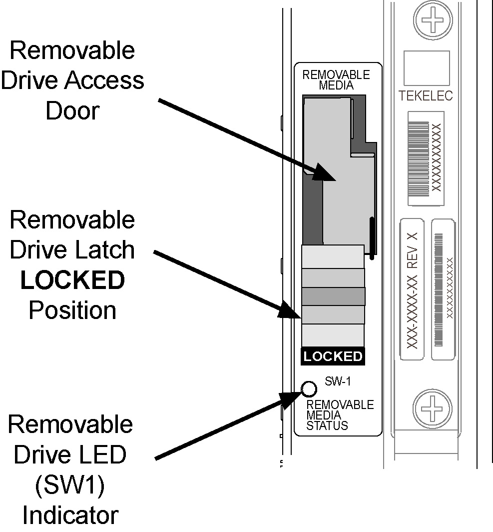
  1. Locate the power source for the EAGLE.
  2. Using a VOM, measure the -48VDC supply.
  3. Verify voltages are between -46VDC and -52VDC.
    (If voltages are higher or lower, refer to the manufacturers maintenance procedures for appropriate action).

2.8 Semi-Annual Procedures

The procedure found in this section is recommended for semi-annual (every 6 months) routine preventive maintenance. Some procedures may refer to other chapters within this document.

Spare Inventory Rotation
Purpose:
The purpose of this routine is to verify the integrity of spare cards. By rotating spares on a regular basis, their operation can be verified before they are needed as replacements.
Requirements
None
Interval
Semi-annually (every 6 months)
Procedure - Semi-annual Procedures
  1. Identify the spare cards in your inventory.

    warning:

    This procedure may interrupt service. Verify the type of card and service it provides, and only use this routine during the maintenance window.
  2. Locate the card in service that matches the configuration of your spare card.
  3. Verify the part numbers and revision numbers of the cards are compatible.
  4. Refer to Card Removal/Replacement Procedures for the proper procedure for each card type.
  5. Place the card from your spares inventory into the now empty slot.
    Perform any administrative commands described in Card Removal/Replacement Procedures.
  6. Make an entry in the site maintenance log and place the card removed from the system into your spares inventory.