5 End Office Support
Chapter 5, End Office Support, describes the procedures necessary to allow the EAGLE to share its true point code (TPC) with an IP-based node without the need for a separate point code for the IP node.
5.1 Overview
End Office Support enables the EAGLE to share its true point code (TPC) with an IP-based node without the need for a separate point code for the IP node. When the End Office Support feature is in use, the EAGLE shares a point code for up to three network types with attached IP network elements.
The EAGLE lets you take advantage of next generation network technology by migrating existing signaling end points from the PSTN to the IP network. The fact that the EAGLE is a signaling transfer point and has its own point code, however, can present a significant network management issue. This feature provides the means to perform the migration without obtaining a new point code or reconfiguring the network to interface with both the EAGLE and an IP end office node.
Characteristics of this feature include:
- The EAGLE allows a set of IP network elements to share its true point code.
- The EAGLE allows messages destined to its true point code and having SI>=3 to be forwarded to an IP network element.
- The EAGLE enables IP networks elements sharing its true point code to participate in network management.
- The EAGLE supports ANSI, ITU national and international end office nodes.
- The EAGLE implements the MTP procedures required for an end office node.
- The End Office Support feature does not reduce the rated TPS of any EAGLE application.
The Remote Application Table contains fields for assigning each user part to an end office node. The default value is 'not assigned'.
New Remote Application Table commands provide for adding, deleting, and retrieving user-part assignments:
-
ent-rmt-appl -
dlt-rmt-appl -
rtrv-rmt-appl
The user parts SI=0, SI=1, and SI=2 cannot be assigned to an end office node. The SNM case is a special case in that UPUs may be forwarded, even though SI=0 cannot be assigned to a remote application. All other SNMs are processed as destined to the EAGLE rather than the end office node. This often results in a multicast throughout the EAGLE that updates the routing tables on all cards. An end office node can receive these messages via replication performed by MTPP.
Each SS7-based application that receives a message destined to a TSPC checks the user-part assignment within the Remote Application Table. If the user-part is assigned and the SI is greater than or equal to 3, then the message is forwarded to the appropriate application, otherwise it is processed as though destined to the EAGLE.
To assign a remote application for the SCCP (SI=3) user part, you must also specify a subsystem number. The Remote Application Table maintains a record of assignments for all possible subsystems (256). Subsystems are either assigned or not assigned.
Note:
SSN=0 is normally an invalid value. This feature makes use ofSSN=0 for the purpose of forwarding certainMSUs to the end office node.- Received SCCP Messages that indicate route-on-global-title are treated as having SSN=0 for remote application assignment. If a remote application is assigned to SSN=0, then the message is forwarded, otherwise it is distributed to the local SCCP application. In previous releases, this would occur only for mis-configured networks. Messages indicating route-on-global-title and intended for the EAGLE, not the end office node, should be sent to the EAGLE's capability point code.
- Received SCCP Messages that lack a Called Party SS are treated as having SSN=0 for remote application assignment. If a remote application is assigned to SSN=0, then the message is forwarded, otherwise it is distributed to the local SCCP application.
- Received SCCP Messages having a Called Party SS equal to SCMG (SSN=1) are processed and terminated by the EAGLE, and if SSN=1 has a remote application assigned, the MSU is also replicated and forwarded to the end office node.
- Received SSCP Messages having a Called Party SSN not equal to 0 or SCMG (1) and for which a remote application is assigned are forwarded to the end office node. Messages received for unassigned subsystems are distributed to the local SCCP application.
- The end office node cannot share SCCP subsystems (other than SCMG) with the EAGLE. If the end office node assigns a given subsystem, such as LNP, then the subsystem local to the EAGLE cannot receive messages. Remote applications take priority over local applications.
Internal Point Code
To route SS7 messages to the IP address without adding another external point code, the End Office feature uses an internal point code (IPC). This point code is private to the EAGLE, and the PSTN has no awareness of it. Its sole purpose is to allow messages destined to the End Office Node to be routed from the inbound LIM to the IPGWx card (a card running either the SS7IPGW or IPGWI applications). An IPC must be entered as a destination and must be assigned for each network type having an end office node. This point code is also used internally by the EAGLE in order to route inbound messages to the outbound IPGWx card. The EAGLE can have up to three IPCs, one for ANSI, one for ITU International, and one for ITU National networks.
Table 5-1 displays a sample Remote Application Table. The Network Type and SI are used to index into the table, rather than being stored in the table.
Table 5-1 Sample IPC Values
| IPC | Assigned to End Office Node | Assigned SSNs | Network Type | User-Part (SI) | Action taken when MSU is received for the TPC |
|---|---|---|---|---|---|
|
p-0-1-0 |
FALSE |
n/a |
ANSI |
0 |
No application can be assigned for SI=0. Note that TFCs are processed, replicated and sent to an end office node, if an application is assigned to any other user part. UPUs are forwarded if the application specified by the affected SI is assigned. |
|
FALSE |
n/a |
1 |
No application can be assigned for SI=1. |
||
|
FALSE |
n/a |
2 |
No application can be assigned for SI=2. |
||
|
TRUE |
3, 7, 100 |
3 |
SCCP messages destined to the TSPC and with SSN assigned are forwarded to an end office node. SCCP messages destined to a TSPC and SSN not assigned are distributed to subsystems local to the EAGLE (e.g. LNP). |
||
|
FALSE |
n/a |
4 |
Terminate with UPU. |
||
|
TRUE |
n/a |
5 |
ISUP messages destined to a TSPC are forwarded to the end office node. |
||
|
FALSE |
n/a |
6 - 15 |
Terminate with UPU. |
||
|
110 |
FALSE |
n/a |
ITU-N |
0 |
No application can be assigned for SI=0. TFCs are processed, replicated and sent to an end office node, if an application is assigned to any other user part. UPUs are forwarded if the application specified by the affected SI is assigned. |
|
FALSE |
n/a |
1 |
No application can be assigned for SI=1. |
||
|
FALSE |
n/a |
2 |
No application can be assigned for SI=2. |
||
|
FALSE |
NULL |
3 |
Distribute to local SCCP. |
||
|
TRUE |
n/a |
4 |
TUP messages destined to the TSPC are forwarded to the end office node. |
||
|
FALSE |
n/a |
5 - 12 |
Terminate with UPU. |
||
|
TRUE |
n/a |
13 |
QBICC messages destined to the TSPC are forwarded to the end office node. |
||
|
FALSE |
n/a |
14, 15 |
Terminate with UPU. |
||
|
0-10-1 |
FALSE |
n/a |
ITU-I |
0 |
No application can be assigned for SI=0. TFCs are processed, replicated and sent to an end office node, if an application is assigned to any other user part. UPUs are forwarded if the application specified by the affected SI is assigned. |
|
FALSE |
n/a |
1 |
No application can be assigned for SI=1. |
||
|
FALSE |
n/a |
2 |
No application can be assigned for SI=2. |
||
|
FALSE |
NULL |
3 |
Distribute to local SCCP. |
||
|
TRUE |
n/a |
4 |
TUP messages destined to the TSPC are forwarded to the end office node. |
||
|
FALSE |
n/a |
5 - 15 |
Terminate with UPU. |
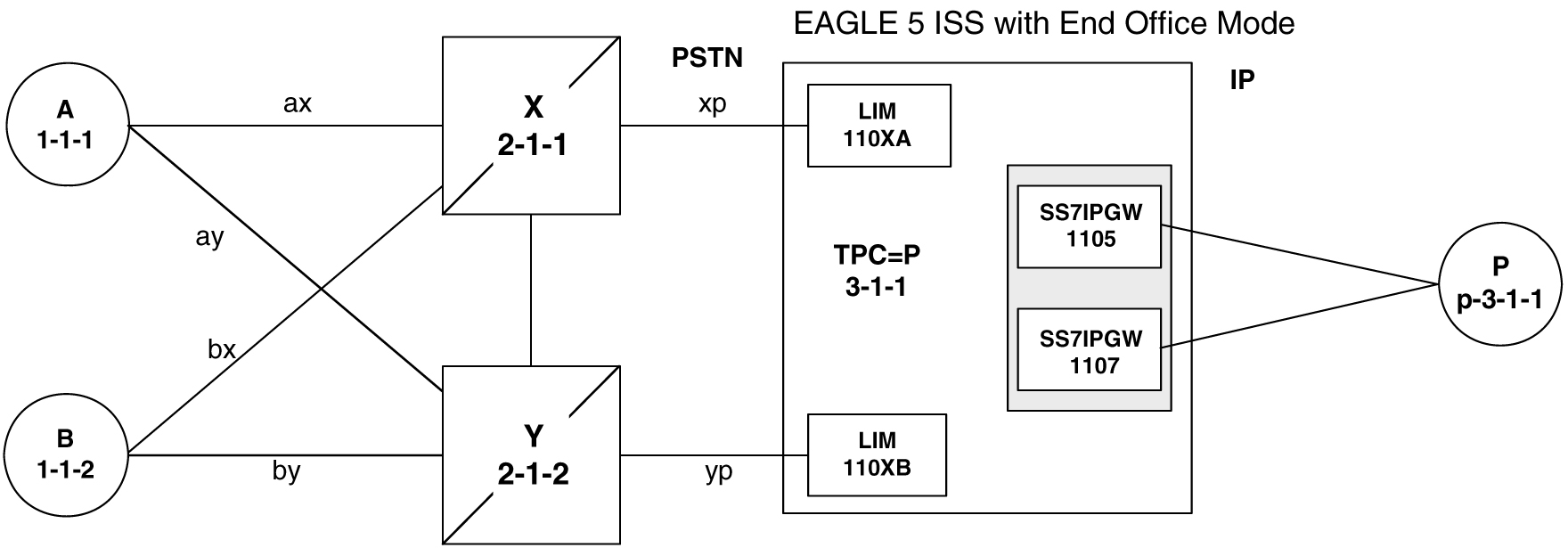
New Installation of VXI Behind a EAGLE with End Office Support
Figure 5-1 depicts a network in which a VXI node is deployed behind a EAGLE with End Office Support. Note that the VXI node resides in the IP network and shares the EAGLE's true point code. The PSTN views the EAGLE and VXI as one network element (one point code).
Figure 5-1 An EAGLE with End Office Support and VXI Node
One Node Migrates from PSTN to IP
Figure 5-2 and Figure 5-3 depict the migration of a signaling end point from the PSTN to an IP network using the EAGLE with the End Office Support feature.
Figure 5-2 Network Before an EAGLE with End Office, Node P is to Migrate
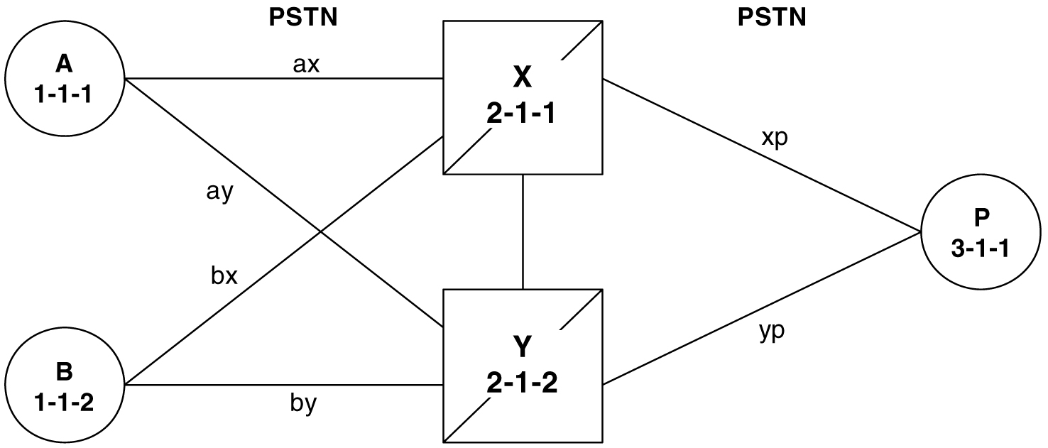
Figure 5-3 Network After an EAGLE with End Office, Node P has Migrated
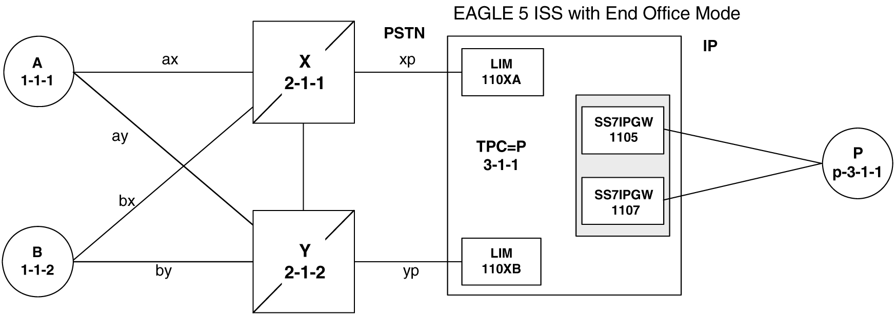
In Figure 5-3 the EAGLE no longer acts like a signaling transfer point, but rather acts like a signaling end point that has an IP-attached application user-part. The EAGLE and the IP network element share the point code P. All messages received by the EAGLE should be destined to P and all messages sent to the PSTN from the EAGLE have an OPC of P.
A Signaling End Point is Added to a Deployed EAGLE Using End Office
Another possible scenario for the End Office feature is that a customer has a deployed EAGLE with attached IP nodes, and wants to make use of the End Office feature to add a new IP node. Consider the following network diagrams, Figure 5-4 and Figure 5-5.
Figure 5-4 Original Network with Deployed EAGLE
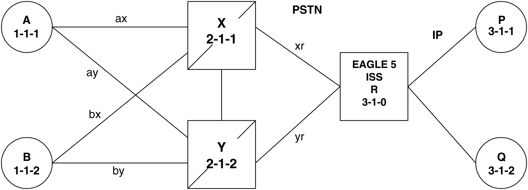
Figure 5-5 New Network with an EAGLE Using End Office and End Node R
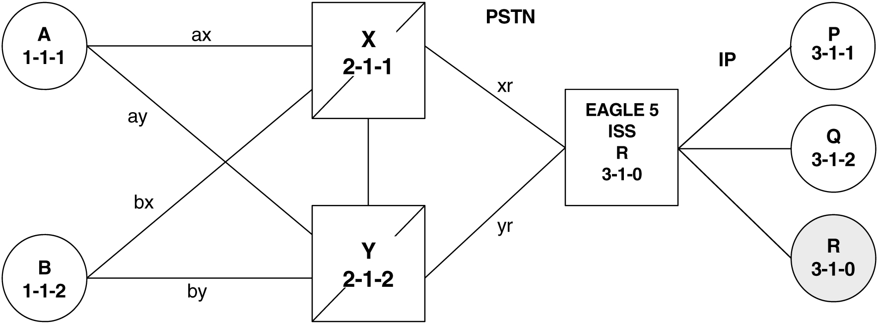
In Figure 5-5 the customer saves a point code by using the End Office feature and making the new IP network element an end office node. No change is required in the PSTN or at P or Q. Non-network-management and non-test messages destined to R are now forwarded to an IP network element, rather than terminated by the EAGLE.
Two Signaling End Points Move from PSTN to IP Using End Office
A more complex scenario arises when multiple signaling end points are to migrate from the PSTN to an IP network using the End Office feature. Consider Figure 5-6 and Figure 5-7.
Figure 5-6 Network before Two Signaling End Points Migrate from PSTN to IP
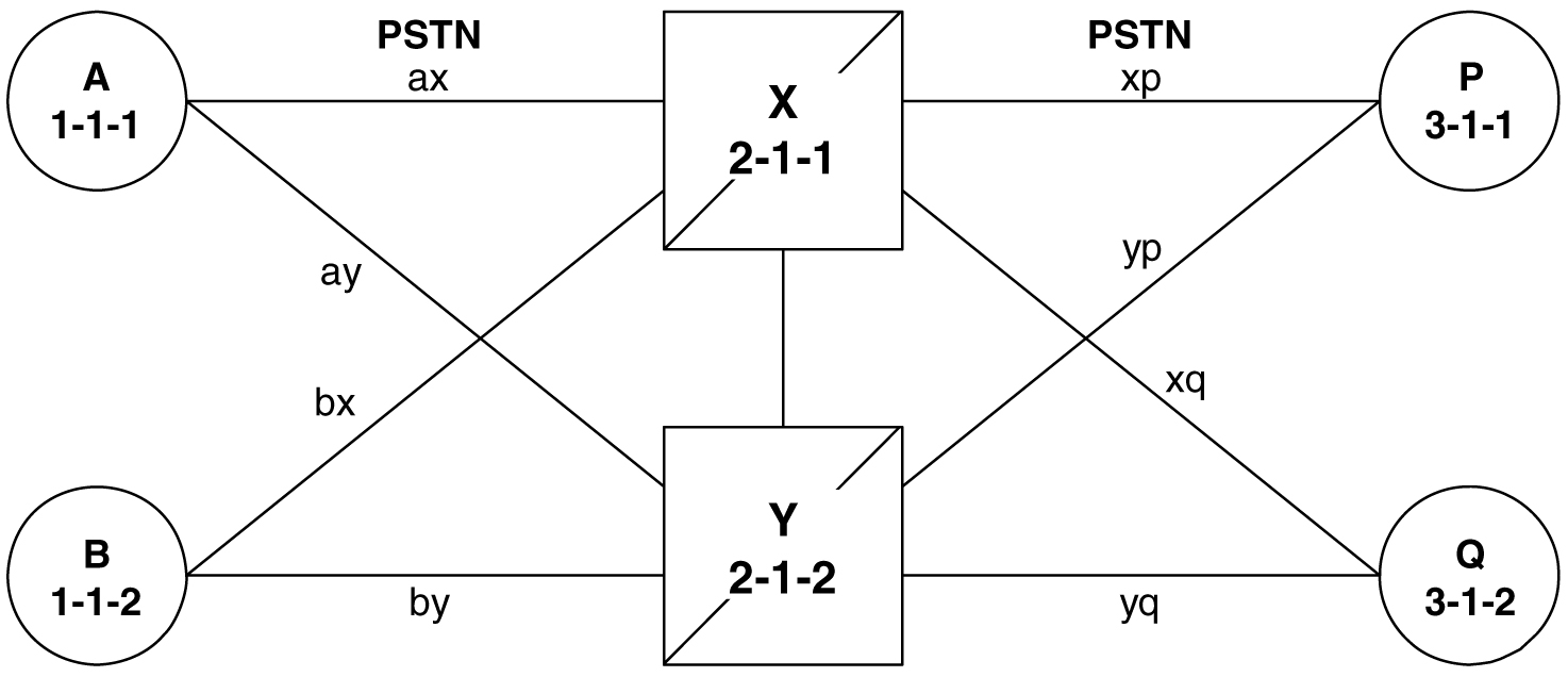
Figure 5-7 Network after Two Signaling End Points Migrate from PSTN to IP
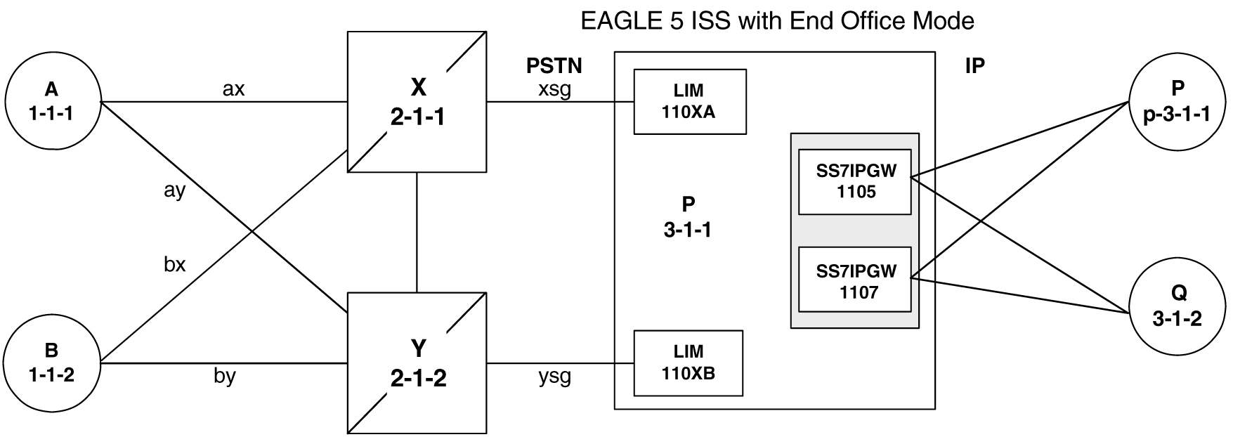
In Figure 5-7, P is an end office node, and so P serves as the adjacent point code for nodes X and Y. The following are key points about this figure:
- Q is not an end office node, and so the EAGLE behaves as an STP for messages originated by and destined to Q.
- Reprovisioning is required in the PSTN, since the Q is now behind P. One example of this is that the linksets between X and Q and between Y and Q must change.
- Traffic between P and Q are no longer routed through X/Y, but are routed within the EAGLE .
The EAGLE Simultaneously Acts as STP and End Office
Figure 5-8 depicts the EAGLE supporting three IP network elements, only one of which use the End Office feature, and two PSTN network elements. In addition, a capability point code is provisioned on the EAGLE, thereby allowing the use of GTT.
Figure 5-8 The EAGLE Simultaneously Acts as STP and End Office
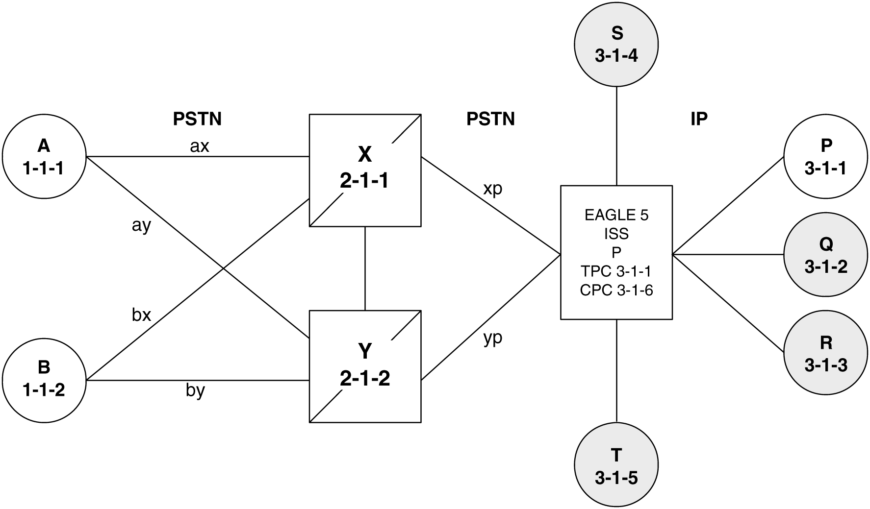
Notes regarding Figure 5-8:
- P is the end office node, and so the EAGLETPC=P.
- Assume that end node P has an application assignment for SCCP.
-
SCCP traffic destined to P is forwarded to the IP node via the SS7IPGW application.
- SCCP traffic destined to the CPC is distributed to the EAGLE’s local SCCP application (e.g. GTT).
- Network elements Q, R, S, and T are not end office nodes, and so the EAGLE generates TFx network management concerning them.
- IP Network element P is an end office node, and so the EAGLE generates only UPU/SSP concerning it.
The EAGLE Supports Multiple Network Types and Multiple Hosts as an End Node
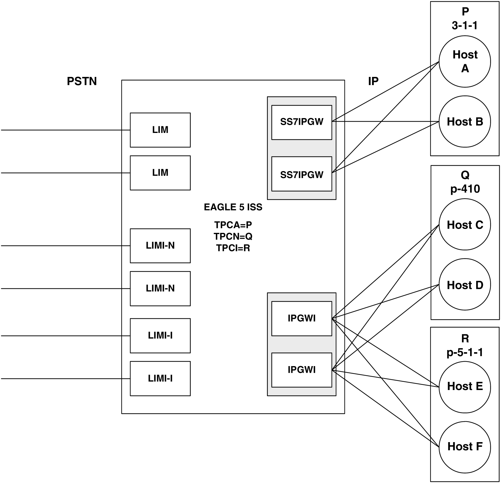
In Figure 5-9 the EAGLE supports an end office node for each of the three network types. Each end office node comprises multiple IP network elements. The IP network elements are distinguished by the remote host and remote port values of the IP network elements (IP address parameters).
Figure 5-9 Three Multiple-Element End Office Nodes
Mated Pair Supports Two End Office Nodes
Figure 5-10 depicts a mated pair of EAGLEs with each EAGLE supporting an End Office Node. Note that EAGLE P lacks IP links to IPNE-Q and EAGLE Q lacks IP links to IPNE-P, since such links would conflict with the C-links of linkset pq.
Figure 5-10 Mated Pair Supports Two End Office Nodes
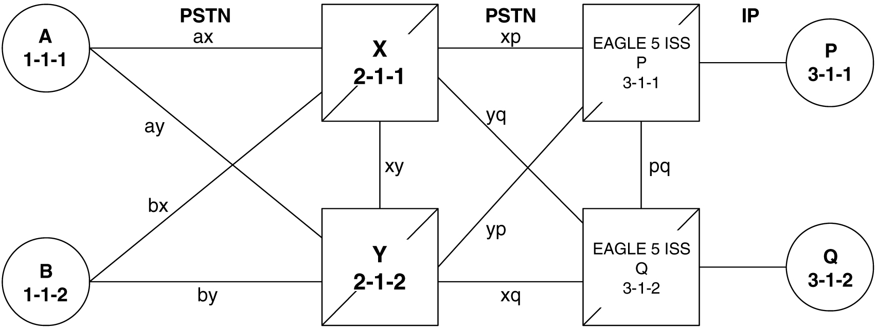
Figure 5-10 shows that a mated pair of EAGLEs cannot share an End Office Node. Each EAGLE requires its own unique point code and so any attached End Office Nodes share those point codes. It would be possible for a single IP network element to act as both P and Q (have IP connections to both EAGLE P and EAGLE Q). This configuration, however, would not provide true redundancy. Messages destined to P are terminated either at EAGLE P or IPNE-P, and message destined to Q are terminated either at EAGLE Q or IPNE-Q. Should the IP link between EAGLE P and IPNE-P fail, this feature provides no way for EAGLE P to forward messages to the End Office Node using the linkset pq (the linkset between systems P and Q).
5.2 End Office Support Configuration
In addition to the internal point code provisioned in the database with the Adding an End Node Internal Point Code procedure, other entities must be configured in the database to support the End Office feature.
For IPGWx entities, these entities must be configured in the database.
- The internal point code must be in the destination point code table - go to the “Adding a Destination Point Code” procedure in Database Administration - SS7 User's Guide.
- An SS7 route to the internal point code - go to either the “Adding a Route containing an SS7DPC” or “Adding a Route Containing an IPGWx Linkset” procedure in the Database Administration - SS7 User's Guide.
- Signaling links assigned to the cards running either the SS7IPGW or IPGWI applications - Adding an IPGWx Signaling Link in End Office Support
- IPGWx associations (with the corresponding application servers):
- Adding an M3UA or SUA Association procedure in IETF M3UA and SUA Configuration Procedures
- Adding a New Association to a New Application Server procedure in IETF M3UA and SUA Configuration Procedures
- Adding an Existing Association to a New Application Server procedure in IETF M3UA and SUA Configuration Procedures
- Adding a New Association to an Existing Application Server procedure in IETF M3UA and SUA Configuration Procedures
- Adding an Existing Association to an Existing Application Server procedure in IETF M3UA and SUA Configuration Procedures
- Routing key matching the user part specified in the Adding an End Node Internal Point Code procedure and with the DPC of the routing key equal to the true point code of the EAGLE (shown in the
rtrv-sidoutput) - See the Adding a Routing Key Containing an Application Server procedure in IETF M3UA and SUA Configuration Procedures .
For IPSG entities, these entities must be configured in the database.
- The internal point code must be in the destination point code table - perform the “Adding a Destination Point Code” procedure in Database Administration - SS7 User's Guide.
- An SS7 route to the internal point code - perform the “Adding a Route containing an SS7DPC” procedure in Database Administration - SS7 User's Guide.
- M3UA Linksets - Adding an IPSG M3UA Linkset procedure in IPSG M2PA and M3UA Configuration Procedures
- M3UA associations - Adding an IPSG M3UA Association procedure in IPSG M2PA and M3UA Configuration Procedures
- Signaling links assigned to the IPSG cards - Adding an IPSG M3UA Signaling Link procedure in IPSG M2PA and M3UA Configuration Procedures
5.3 Adding an End Node Internal Point Code
This procedure is used to assign user parts to an
internal point code (IPC), and thereby to an end office node using the
ent-rmt-appl command. An internal
point code is assigned to remote applications.
Only one IPC value for each network type can be
configured. If you are adding an IPC value of the same network type as an
existing IPC (for example, adding an ANSI IPC when the
rtrv-rmt-appl output contains an ANSI
IPC), the IPC value must be the same as the existing IPC value.
The
ent-rmt-appl command uses these
parameters:
:ipc/ipca/ipci/ipcn/ipcn24 – The end node's internal
point code can be an ANSI (ipc/ipca), ITU-I or
ITU-I spare (ipci), 14-bit ITU-N or 14-bit
ITU-N spare (ipcn), or 24-bit ITU-N (ipcn24) point code.
Note:
The point code value can also be either a private (p- ) or a private spare (ps- ) point code, but does not have to be a private or private spare point code. Any point code can be a private point code. Only ITU-I or 14-bit ITU-N point codes can be private spare point codes. The point code value must be shown in thertrv-dstn command output.
Note:
The EAGLE can contain 14-bit ITU-N point codes or 24-bit ITU-N point codes, but not both at the same time.:si – The service
indicator value designates which MSU user part is being assigned to a remote
application. Valid values range from 3 to 15.
:ssn – The SCCP
subsystem number parameter. This parameter is required if the
si=3 parameter is specified and is not
valid for any other
si value. If the
ssne parameter is also specified, then
the
ssn parameter serves as the starting
value of a range. Valid values range from 0 to 255.
:ssne – The SCCP
subsystem number range end parameter. The
ssne value can be specified only if the
si=3 parameter is specified and is not
valid for any other
si value. This parameter serves as an
end of a range, and so must be greater than the
ssn parameter value. Valid values range
from 1 to 255.
The specified assignment cannot be an existing assignment, including SSN subsets.
Figure 5-11 Add an End Node Internal Point Code
5.4 Removing an End Node Internal Point Code
The dlt-rmt-appl command is used to remove remote application assignments from the database.
The dlt-rmt-appl command uses these parameters:
:ipc/ipca/ipci/ipcn/ipcn24 – The end node's internal point code can be an ANSI, ANSI private (ipc/ipca), ITU-I, ITU-I spare, ITU-I private spare (ipci), 14-bit ITU-N, 14-bit ITU-N spare, 14-bit ITU-N private spare (ipcn), or 24-bit ITU-N, or 24-bit ITU-N private (ipcn24) point code.
:si – The service indicator value designates which MSU user part is being assigned to a remote application. Valid values range from 3 to 15.
:ssn – The SCCP subsystem number parameter. This parameter is required if the si=3 parameter is specified and is not valid for any other si value. If the ssne parameter is also specified, then the ssn parameter serves as the starting value of a range. Valid values range from 0 to 255.
:ssne – The SCCP subsystem number range end parameter. The ssne value can be specified only if the si=3 parameter is specified and is not valid for any other si value. This parameter serves as an end of a range, and so must be greater than the ssn parameter value. Valid values range from 1 to 255.
Figure 5-12 Removing an End Node Internal Point Code