Overview of Deployment Scenarios
This section describes common Converged Application Server network architectures and network configuration considerations for each architecture, particularly in relation to the Open Systems Interconnect (OSI) model. See Converged Application Server Administrator's Guide for detailed configuration steps described in this section.
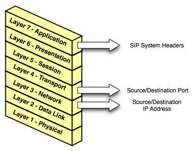
Figure 5-1 shows the OSI model layers that are typically affected by the network configuration requirements for the Converged Application Server deployment.
Figure 5-1 OSI Layers Relevant to Converged Application Server Configuration

Layer 3 (Network) and Layer 4 (Transport) contain the source or destination IP address and port numbers for both outgoing and incoming transport datagrams. Layer 7 (Application) may also be affected because the SIP protocol specifies that certain SIP headers include addressing information for contacting the sender of a SIP message.
Single-NIC Configurations with TCP and UDP Channels
In a simple network configuration for a server having a single network interface controller (NIC), one or more network channels may be created to support SIP messages over User Datagram Protocol (UDP) and Transmission Control Protocol (TCP), or Session Initiation Protocol (SIP) over Transport Layer Security (TLS). It is helpful to understand how this simple configuration affects information in the OSI model, so that you can understand how more complex configurations involving multihomed hardware and load balancers affect the same information.
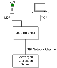
Figure 5-2 Single-NIC Network Channel

Figure 5-2 shows a single engine tier server instance with a single NIC. The server is configured with one network channel supporting SIP over UDP and TCP. (SIP channels always support both UDP and TCP transports; you cannot support only one of the two.) The scenario also shows two clients communicating with the server, one over UDP and one over TCP.
For the TCP transport, the outgoing datagram (delivered from Converged Application Server to the UA) contains the following information:
- Layer 3 includes the source IP address specified by the network channel (10.1.1.10 in the example above).
- Layer 4 includes the source port number allocated by the underlying operating system.
Incoming TCP datagrams (delivered from the UA to Converged Application Server) contain the following information:
- Layer 3 includes the destination IP address specified by the network channel (10.1.1.10).
- Layer 4 contains the destination port number specified by the network channel (5060).
For outgoing UDP datagrams, the OSI layer information contains the same information as with TCP transport. For incoming UDP datagrams, the OSI layer information is the same as TCP except in the case of incoming datagram Layer 4 information. For incoming UDP datagrams, Layer 4 contains either:
- The destination port number specified by the network channel (5060), or
- The ephemeral port number previously allocated by Converged Application Server.
By default Converged Application Server allocates ports from the ephemeral port number range of the underlying operating system for outgoing UDP datagrams. Converged Application Server allows external connections to use an ephemeral point as the destination port number, in addition to the port number configured in the network channel. In other words, Converged Application Server automatically listens on all ephemeral ports that the server allocates. You can optionally disable Converged Application Server's use of ephemeral port numbers and setting a static port, as described in Oracle Communications Converged Application Server Administrator's Guide.
Multihomed Server Configurations Overview
Engine tier servers in a production deployment frequently utilize multihomed server hardware, having two or more NICs. Multihomed hardware is typically used for one of the following purposes:
-
To provide redundant network connections within the same subnet. Having multiple NICs ensures that one or more network connections are available to communicate with SIP data tier servers or the Administration Server, even if a single NIC fails.
-
To support SIP communication across two or more different subnets. For example Converged Application Server may be configured to proxy SIP requests from UAs in one subnet to UAs in a second subnet, when the UAs cannot directly communicate across subnets.
The configuration requirements and OSI layer information differ depending on the use of multihomed hardware in your system. When multiple NICs are used to provide redundant connections within a subnet, servers are generally configured to listen on all available addresses (IP_ANY) as described in "Multihomed Servers Listening On All Addresses (IP_ANY)".
When using multiple NICs to support different subnets, you must configure multiple network on the server for each different NIC as described in "Multihomed Servers Listening on Multiple Subnets".
Multihomed Servers Listening On All Addresses (IP_ANY)
The simplest multihome configuration enables a Converged Application Server instance to listen on all available NICs (physical NICs as well as logical NICs), sometimes described as IP_ANY. To accomplish this, you configure a single network channel and specify a channel listen address of 0.0.0.0.
See information about configuring engine servers to listen on any IP interface in the Converged Application Server Administrator's Guide.
Multihomed Servers Listening on Multiple Subnets
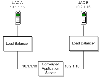
Multiple NICs can also be used in engine tier servers to listen on multiple subnets. The most common configuration uses Converged Application Server to proxy SIP traffic from one subnet to another where no direct access between subnets is permitted. Figure 5-3 shows this configuration.
Figure 5-3 Multihomed Configuration for Proxying between Subnets

To configure the Converged Application Server instance in this scenario, you
must define a separate network channel for each NIC used on the server machine. Example 5-1 shows the config.xml entries that define channels
for the sample configuration.
Example 5-1 Sample Network Channel Configuration for NICs on Multiple Subnets
<NetworkAccessPoint ListenAddress="10.1.1.10" ListenPort="5060" Name="sipchannelA" Protocol="sip"/>
<NetworkAccessPoint ListenAddress="10.2.1.10" ListenPort="5060" Name="sipchannelB" Protocol="sip"/>
Understanding the Route Resolver
When Converged Application Server is configured to listen on multiple subnets, a feature called the route resolver is responsible for the following activities:
-
Populating OSI Layer 7 information (SIP system headers such as Via and Contact) with the correct address.
-
Populating OSI Layer 3 information with the correct source IP address.
For example, in the configuration shown in Figure 5-3, Converged Application Server must add the correct subnet address to SIP system headers and transport datagrams in order for each UA to continue processing SIP transactions. If the wrong subnet is used, replies cannot be delivered because neither UA can directly access the other UA's subnet.
The route resolver works by determining which NIC the operating system will use to send a datagram to a given destination, and then examining the network channel that is associated with that NIC. It then uses the address configured in the selected network channel to populate SIP headers and Layer 3 address information.
For example, in the configuration shown in Figure 5-3, an INVITE message sent from Converged Application Server to UAC B would have a destination address of 10.2.1.16. The operating system would transmit this message using NIC B, which is configured for the corresponding subnet. The route resolver associates NIC B with the configured sipchannelB and embeds the channel's IP address (10.2.1.10) in the VIA header of the SIP message. UAC B then uses the Via header to direct subsequent messages to the server using the correct IP address. A similar process is used for UAC A, to ensure that messages are delivered only on the correct subnet.
IP Aliasing with Multihomed Hardware
IP aliasing assigns multiple logical IP addresses to a single NIC, and is configured in the underlying server operating system. If you configure IP aliasing and all logical IP addresses are within the same subnet, you configure Converged Application Server to listen on all addresses.
If you configure IP aliasing to create multiple logical IP addresses on different subnets, you must configure a separate network channel for each logical IP address. In this configuration, Converged Application Server treats all logical addresses as separate physical interfaces (NICs) and uses the route resolver to populate OSI Layer 4 and Layer 7 information based on the configured channel.