2 Deploy with the Container Engine for Kubernetes

The Converged Application Server can be deployed in OCI using Oracle's Container Engine for Kubernetes.

Oracle Cloud Infrastructure Container Engine for Kubernetes is a fully-managed, scalable, and highly available service that you can use to deploy your containerized applications to the cloud. Use Container Engine for Kubernetes (abbreviated OKE) when your development team wants to reliably build, deploy, and manage cloud-native applications. You specify whether to run applications on virtual nodes or managed nodes, and Container Engine for Kubernetes provisions them on Oracle Cloud Infrastructure in an existing OCI tenancy.

To learn more about OKE, view the OKE documentation.

Architecture Overview

The Converged Application Server deployed with OKE uses the following OCI services:

  • Container Engine for Kubernetes: The Container Engine for the Kubernetes cluster has three worker nodes so that the OCCAS-Coherence clusters themselves have the highest availability.
  • File Storage: The domain configuration files are stored on shared storage that is accessible from all WebLogic servers in the cluster, on File Storage. Because of this setup, you don't need to rebuild Docker images for changes in the domain configuration, backup is faster and centralized, and logs are stored by default on persistent storage.
  • Load Balancing: By default, the WebLogic servers (admin or clustered managed servers) created by the operator (WKO) are not exposed outside the Container Engine for Kubernetes cluster. The Converged Application Server uses the OCI Network Load Balancer, which supports TCP and UDP, to expose an application to the outside world.
  • Registry: A Converged Application Server image can be pulled from https://container-registry.oracle.com/. Optionally, the Docker images can be stored in a private Oracle Cloud Infrastructure Registry repository.
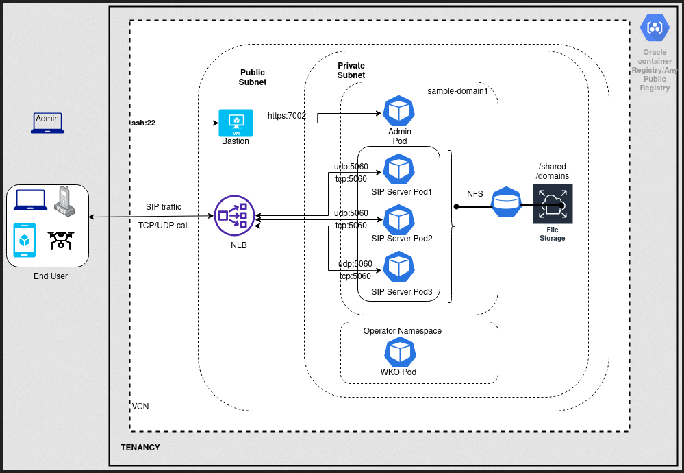
occas-oke-arch

Create the Kubernetes Cluster

Before creating a Kubernetes cluster, follow the steps in Preparing for Container Engine for Kubernetes to set the correct Identity and Access Management (IAM) policy.

  1. Log in to the Console for your OCI Tenancy.
  2. From the OCI Menu, select Developer Services and then Container Clusters (OKE).
  3. If the compartment has not been set, select your compartment from the left-hand drop-down list.
  4. Click Create Cluster and then Quick Create and then Submit.
  5. Enter a name for the cluster.
  6. Select the Kubernetes version.
  7. Select Managed Node type.
  8. Select the shape of each worker node in the cluster and the number of nodes in each subnet.

    To ensure the highest performance for those demanding workloads, Container Engine for Kubernetes allows you to select bare metal instances or even GPU instances on which to run your containers.

  9. Click Next and then Create cluster.
  10. After the cluster is created, you access the cluster in one of two ways:
    • Using kubectl in Cloud Shell
    • Using kubectl installed locally

    See Accessing a Cluster Using Kubectl for more information.

  11. Run kubectl cluster-info or kubectl config view to confirm the configuration.

After the cluster has been created:

  1. Select Menu, and then Networking, and thenVNC.
  2. Note the subnets and their CIDR blocks.

Create and Configure the File Storage Service

When deployed with OKE, the Converged Application Server depends on the File Storage service.

  1. From the OCI Menu, select Storage and then Mount Targets under the File Storage section.
  2. Click Create Mount Target
  3. Select the VCN of your cluster and the subnet of your worker nodes.

    If you require extra isolation, you may optionally setup additional VCN routing and security.

  4. Click Create.
  5. Select the created Mount Target.
  6. Under the Exports section, click Create Export to create a file system for the Persistent Volume.
  7. Accept the defaults and click Create.

Create a Virtual Network

  1. From the Console, select Networking and then Virtual Cloud Networks.
  2. Select the VCN assigned to your cluster and the subnet you previously selected when creating an export path.
  3. Select the default Security List.
  4. Create four ingress destination ports: two TCP ports (2048-2050 and 111) and two UDP ports (2048 and 111).
    The IP range must match the CIDR range of your VCN.
  5. Create three egress source ports: two TCP ports (2048-2050 and 111) and one UDP port (111).
    The IP range must match the CIDR range of your VCN.

Create a Storage Class

  1. Create a storage class file called ocistorageclass.yaml

    Use the OCID from the Mount Target as the value of the mntTargetId parameter.

    kind: StorageClass
    apiVersion: storage.k8s.io/v1
    metadata:
        name: sample-domain1-weblogic-sample-storage-class
    provisioner: oracle.com/sample-domain1-weblogic-sample-storage-class
    parameters:
        mntTargetId: <OCID of the created mount target>
  2. Apply the file to create the Storage Class.
    kubectl apply -f ocistorageclass.yaml

Install the Kubernetes Weblogic Operator with OKE

The WebLogic Kubernetes Operator supports running your WebLogic Server domains on Kubernetes. It lets you encapsulate your entire WebLogic Server installation and layered applications into a portable set of cloud neutral images and simple resource description files.

  1. If Helm is not already installed, install Helm.
    curl -fsSL -o get_helm.sh https://raw.githubusercontent.com/helm/helm/main/scripts/get-helm-3
    chmod 700 get_helm.sh
    ./get_helm.sh
  2. Clone the Oracle Weblogic Kubernetes Operator repository.
    The Oracle Weblogic Kubernetes Operator is used to configure the lifecycle of the Converged Application Server images. See the Oracle Weblogic Kubernetes Operator documentation.
    git clone --branch v4.0.5 https://github.com/oracle/weblogic-kubernetes-operator
  3. Pull the Docker image for the WebLogic Kubernetes Operator.
    podman pull ghcr.io/oracle/weblogic-kubernetes-operator:4.0.5

    If your jumpbox or cluster cannot access ghcr.io, check the subnet and gateway settings of your network.

  4. Create the namespace for the Weblogic Kubernetes Operator.

    The syntax for the command is: kubectl create namespace <unique name>. For example:

    kubectl create namespace sample-weblogic-operator-ns
  5. Create the service account within that namespace for the WebLogic Kubernetes Operator.
    kubectl create serviceaccount -n sample-weblogic-operator-ns sample-weblogic-operator-sa
  6. Update the following parameters in the file weblogic-kubernetes-operator/kubernetes/charts/weblogic-operator/values.yaml.

    If you plan on installing the EFK stack, set elkIntegrationEnabled to true; otherwise, leave elkIntegrationEnabled as false.

    • serviceAccount—Set this to the previously created service account for the WebLogic Kubernetes Operator.
      serviceAccount: "sample-weblogic-operator-sa"
    • domainNamespaces—Set this to the previously created namespace for the WebLogic Kubernetes Operator.
      domainNamespaces:
      - "sample-weblogic-operator-ns"
    • elkIntegrationEnabled—Set this to true if you plan on installing the EFK stack; leave as false if you do not plan on installing the EFK stack.
      elkIntegrationEnabled: false
    • elasticSearchHost—Change the word 'default' in 'elasticsearch.default.svc.cluster.local' to the namespace previously created for the WebLogic Kubernetes Operator.
      elasticSearchHost: "elasticsearch.sample-weblogic-operator-ns.svc.cluster.local"
  7. From the weblogic-kubernetes-operator directory, start the operator.
    helm install sample-weblogic-operator kubernetes/charts/weblogic-operator \
      --namespace sample-weblogic-operator-ns \
      --set image=ghcr.io/oracle/weblogic-kubernetes-operator:4.0.5 \
      --set serviceAccount=sample-weblogic-operator-sa \
      --set "enableClusterRoleBinding=true"\
      --set "domainNamespaceSelectionStrategy=LabelSelector"\
      --set "domainNamespaceLabelSelector=weblogic-operator\=enabled"\
      --wait
Verify the pod is running with the following command:
kubectl get pods -n sample-weblogic-operator-ns
For example:
[weblogic-kubernetes-operator]$ kubectl get pods -n sample-weblogic-operator-ns
NAME                                 READY   STATUS    RESTARTS   AGE
weblogic-operator-7885684685-4jz5l   1/1     Running   0          2m32s
[weblogic-kubernetes-operator]$

Note:

If you are installing the EFK stack and set elkIntegrationEnabled to true, then the READY column will display 2/2 when both containers are ready. If you are not installing the EFK stack and left elkIntegrationEnabled as false, then the READY column will display 1/1 when the container is ready.

Download Domain Creation Files

In addition to downloading the occas_generic.jar file, you need to download the domain creation files.

  1. Sign in to My Oracle Support.
  2. Search for "Docker Script for OCCAS 8.1 Installation" (Doc ID 3007597.1).
  3. Under the Details section, click the link to download occas81.zip.
  4. Unzip the file.
    unzip occas81.zip
    This creates the occas81/ directory.

Create a Persistent Volume

Create a persistent volume and a persistent volume claim to make the shared file system accessible from the pods.

  1. Create and label a namespace that can host one or more domains.
    kubectl create namespace sample-domain1-ns
    kubectl label ns sample-domain1-ns weblogic-operator=enabled
  2. Navigate to the occas81/dockerfiles/8.1.0.0.0/occas-domain-home-on-pv directory.
  3. Create Weblogic credentials.
    ./create-weblogic-credentials.sh -u <username> -p <PASSPHRASE> -n sample-domain1-ns -d sample-domain1 -s sample-domain1-weblogic-credentials
  4. Open the sample-domain1-weblogic-sample-pv_nfs.yaml file.
    1. Set the server parameter to the IP address of the OFSS Export Path.
    2. Set the path parameter to the value of your previously configured Export Path.
    apiVersion: v1
    kind: PersistentVolume
    metadata:
      name: sample-domain1-weblogic-sample-pv
      labels:
        weblogic.domainUID: sample-domain1
    spec:
      storageClassName: sample-domain1-weblogic-sample-storage-class
      capacity:
        storage: 5Gi
      accessModes:
        - ReadWriteMany
      # Valid values are Retain, Delete or Recycle
      persistentVolumeReclaimPolicy: Retain
      nfs:
        server: 192.0.2.5
        path: "/FileSystem-20220604-1759-09"
  5. Create the Persistent Volume.
    kubectl create -f sample-domain1-weblogic-sample-pv_nfs.yaml
    kubectl create -f sample-domain1-weblogic-sample-pvc_nfs.yaml

Choose the Image

The Oracle Communications Converged Application Server image is located on the Oracle Container Registry.

  1. If using JDK 8, use the JDK 8 container.
    container-registry.oracle.com/middleware/occas:8.1.0.0.0-generic-8
  2. If using JDK 11, use the JDK 11 container.
    container-registry.oracle.com/middleware/occas:8.1.0.0.0-generic-11

Create Kubernetes Secret

Create a Kubernetes secret in order to pull from a private or public registry.

  1. Use kubectl to create the secret.

    Use your own email address in the docker-username and docker-email parameters.

    kubectl create secret docker-registry occas-image-sec \
      --docker-server=container-registry.oracle.com \
      --docker-username=first.last@oracle.com \
      --docker-password=<token> \
      --docker-email=first.last@oracle.com \
      -n sample-domain1-ns
  2. Log in to the Oracle Container Registry.

    Use the same username and password as above.

    podman login container-registry.oracle.com

Create Domain

The Converged Application Server domain is a logically related group of resources. Domains include the administration server and all managed servers. Converged Application Server domains extend Oracle WebLogic Server domains to support SIP and other telecommunication protocols.

  1. Navigate to the occas81/dockerfiles/8.1.0.0.0/occas-domain-home-on-pv/domain-home-on-pv directory.
  2. Open the create-domain-inputs.yaml file.
  3. Set the following parameters.

    Table 2-1 Parameters

    Parameter Definition Default
    configuredManagedServerCount Name of the WebLogic cluster instance to generate for the domain. 5
    createDomainFilesDir Directory on the host machine to locate all the files to create a WebLogic domain, including the script that is specified in the createDomainScriptName property. By default, this directory is set to the relative path wlst, and the create script will use the built-in WLST offline scripts in the wlst directory to create the WebLogic domain. It can also be set to the relative path wdt, and then the built-in WDT scripts will be used instead. An absolute path is also supported to point to an arbitrary directory in the file system. The built-in scripts can be replaced by the user-provided scripts or model files as long as those files are in the specified directory. Files in this directory are put into a Kubernetes ConfigMap, which in turn is mounted to the createDomainScriptsMountPath, so that the Kubernetes Pod can use the scripts and supporting files to create a domain home. wlst
    domainHome Home directory of the WebLogic domain. If not specified, the value is derived from the domainUID as /shared/domains/<domainUID>. /FileSystem-20220305-1124-54/domains/sample-domain1
    domainPVMountPath Mount path of the domain persistent volume. /FileSystem-20220305-1124-54
    domainUID Unique ID that will be used to identify this particular domain. Used as the name of the generated WebLogic domain as well as the name of the Domain. This ID must be unique across all domains in a Kubernetes cluster. This ID cannot contain any character that is not valid in a Kubernetes Service name. sample-domain1
    exposeAdminNodePort Boolean indicating if the Administration Server is exposed outside of the Kubernetes cluster. true
    exposeAdminT3Channel Boolean indicating if the T3 administrative channel is exposed outside the Kubernetes cluster. true
    httpAccessLogInLogHome Boolean indicating if server HTTP access log files should be written to the same directory as logHome. Otherwise, server HTTP access log files will be written to the directory specified in the WebLogic domain home configuration. true
    image OCCAS generic image container-registry.oracle.com/middleware/occas:8.1.0.0.0-generic-11
    imagePullSecretName Name of the Kubernetes Secret to access the container registry to pull the WebLogic Server image. The presence of the secret will be validated when this parameter is specified occas-image-sec
    initialManagedServerReplicas Number of Managed Servers to start initially for the domain. 2
    javaOptions Java options for starting the Administration Server and Managed Servers. A Java option can have references to one or more of the following pre-defined variables to obtain WebLogic domain information: $(DOMAIN_NAME), $(DOMAIN_HOME), $(ADMIN_NAME), $(ADMIN_PORT), and $(SERVER_NAME). -Dweblogic.StdoutDebugEnabled=false
    logHome The in-pod location for domain log, server logs, server out, introspector out, Node Manager log, and server HTTP access log files. If not specified, the value is derived from the domainUID as /shared/logs/<domainUID>. /FileSystem-20220305-1124-54/domain-home-in-pv/logs
    managedServerPort Port number for each Managed Server. 8001
    namespace Kubernetes Namespace in which to create the domain. sample-domain1-ns
    persistentVolumeClaimName Name of the persistent volume claim. If not specified, the value is derived from the domainUID as <domainUID>-weblogic-sample-pvc sample-domain1-weblogic-sample-pvc
    productionModeEnabled Boolean indicates if production mode is enabled for the domain. true
    serverStartPolicy Determines which OCCAS will be started. Legal values are NEVER, IF_NEEDED, ADMIN_ONLY. IF_NEEDED
    t3ChannelPort Port for the T3 channel of the network access point. 30012
    t3PublicAddress Public address for the T3 channel. This should be set to the public address of the Kubernetes cluster. This would typically be a load balancer address. For development environments only, in a single server (all-in-one) Kubernetes Deployment, this may be set to the address of the master, or at the very least, it must be set to the address of one of the worker nodes. If not provided, the script will attempt to set it to the IP address of the Kubernetes cluster.
    sipPublicAddress The public listen to address to embed in SIP headers when the channel is used for an outbound connection. This is typically the IP address presented by the IP sprayer or external load balancer as the virtual IP (VIP) for the telecommunication servicesif sipPublicAddress is blank, Operator will assign kubernetes internal address same as ListenAddress Like sample-domain1-managed-server1 Load Balancer private address
    weblogicCredentialsSecretName Name of the Kubernetes Secret for the Administration Server user name and password. If not specified, the value is derived from the domainUID as <domainUID>-weblogic-credentials. domain1-weblogic-credentials

    serverPodCpuRequest

    serverPodMemoryRequest

    serverPodCpuCLimit

    serverPodMemoryLimit

    The maximum amount of compute resources allowed, and minimum amount of compute resources required, for each server pod. Please refer to the Kubernetes documentation on "Managing Compute Resources for Containers" for details. Resource requests and resource limits are not specified.

    In the generated YAML files, the names of the Kubernetes resources are formed from values specified in the create-inputs.yaml file. Invalid characters like uppercase letters or underscores are converted to lowercase letters and hyphens.

  4. Update the fix-pvc-owner item of create-domain-job-template.yaml file.
    ...
    initContainers:
      - name: fix-pvc-owner
        image: %WEBLOGIC_IMAGE%
        command: ["sh", "-c", "chown 1000:0 %DOMAIN_ROOT_DIR%/. && find %DOMAIN_ROOT_DIR%/. -maxdepth 1 ! -name '.snapshot' ! -name '.' -print0 | xargs -r -0 chown -R 1000:0"]          
        volumeMounts:
    ...
  5. Use the create-domain.sh script to create the domain.
    The command requires two arguments: the input YAML file and the output directory.
    ./create-domain.sh \
        -i create-domain-inputs.yaml \
        -o ~/occas81/dockerfiles/8.1.0.0.0/occas-domain-home-on-pv/domain-home-on-pv
  6. Navigvate to the sample-domain1 folder.
    cd weblogic-domains/sample-domain1/
  7. Deploy the WebLogic domain in the Kubernetes cluster.
    kubectl apply -f domain.yaml
    The domain will now be managed by the Weblogic Operator.
  8. Create an SSH tunnel through your bastion host to access the Administrator Console. Open a browser and navigate to http://<IP address>:30701/console to visit the WebLogic Server's management interface.

Create Load Balancers

  1. Create a nlb.yaml file that defines the network load balancer.
    apiVersion: v1
    kind: Service
    metadata:
      name: occas-nlb
      namespace: sample-domain1-ns
      annotations:
        oci.oraclecloud.com/load-balancer-type: "nlb"
        oci-network-load-balancer.oraclecloud.com/security-list-management-mode: "All"
    spec:
      type: LoadBalancer
      ports:
      - port: 5060
        targetPort: 5060
        protocol: TCP
      selector:
        weblogic.clusterName: bea-engine-tier-clust
        weblogic.createdByOperator: "true"
        weblogic.domainUID: sample-domain1
  2. Apply the file.
    kubectl apply -f nlb.yaml
  3. From the OCI Console, select Networking and then Load Balancer and confirm the load balancer was successfully created.