Maintenance Without Power
Some maintenance tasks must be performed after powering down the system.
- Remove and replace the front bezel
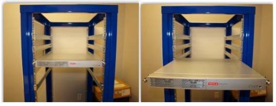
- Remove the chassis from an equipment rack
- Remove the chassis cover
- Remove and replace transcoder DSP modules
- Remove and replace T1/E1 TDM modules
- Replace the main board (motherboard)
Remove and Replace the Front Bezel
- To remove the bezel, pull on its left corner.
- To replace the bezel, hook the right to its slots and press the left side forward until the magnet catches.
Remove the Chassis Cover
Caution:
Always gracefully power down the Acme Packet 4900 and then disconnect the power supplies from the power source when removing the chassis cover.- Remove Acme Packet 4900 from the rack.
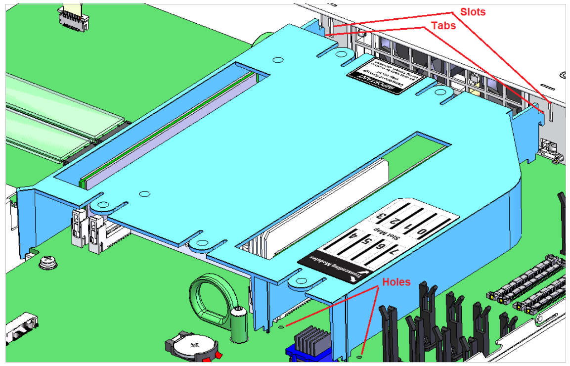
- Push the chassis cover backwards about ½ inch.
- Lift the cover up until it is free of the chassis.
Replacing Transcoder Modules
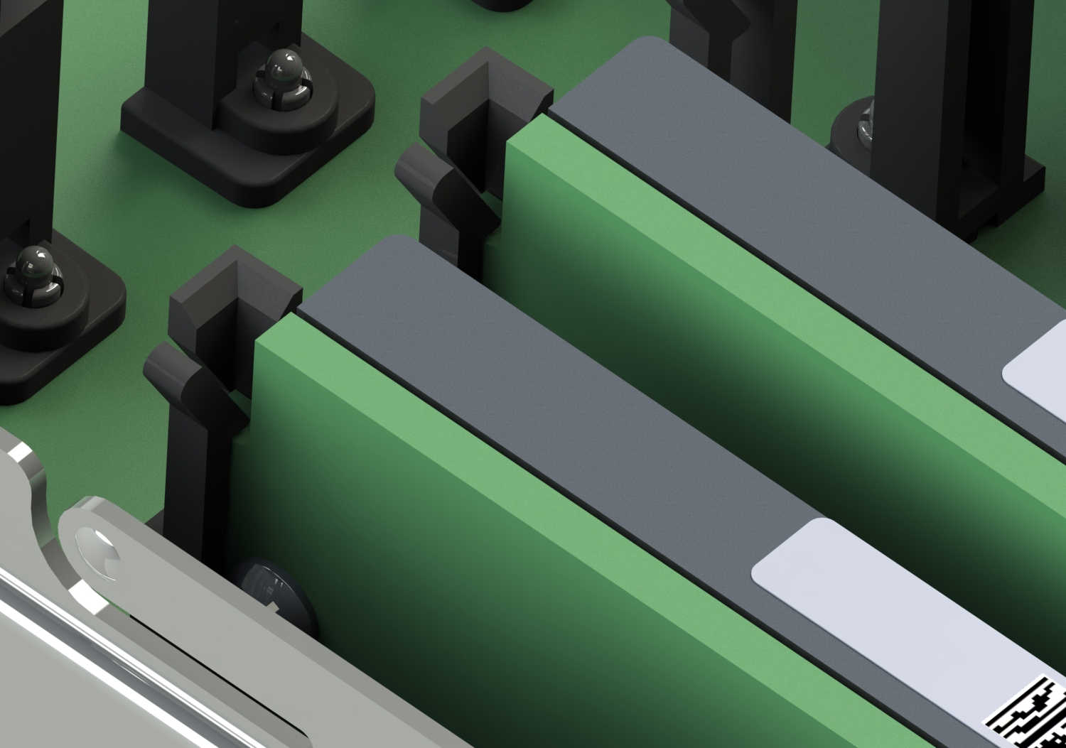
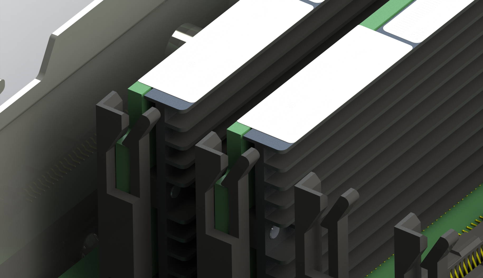
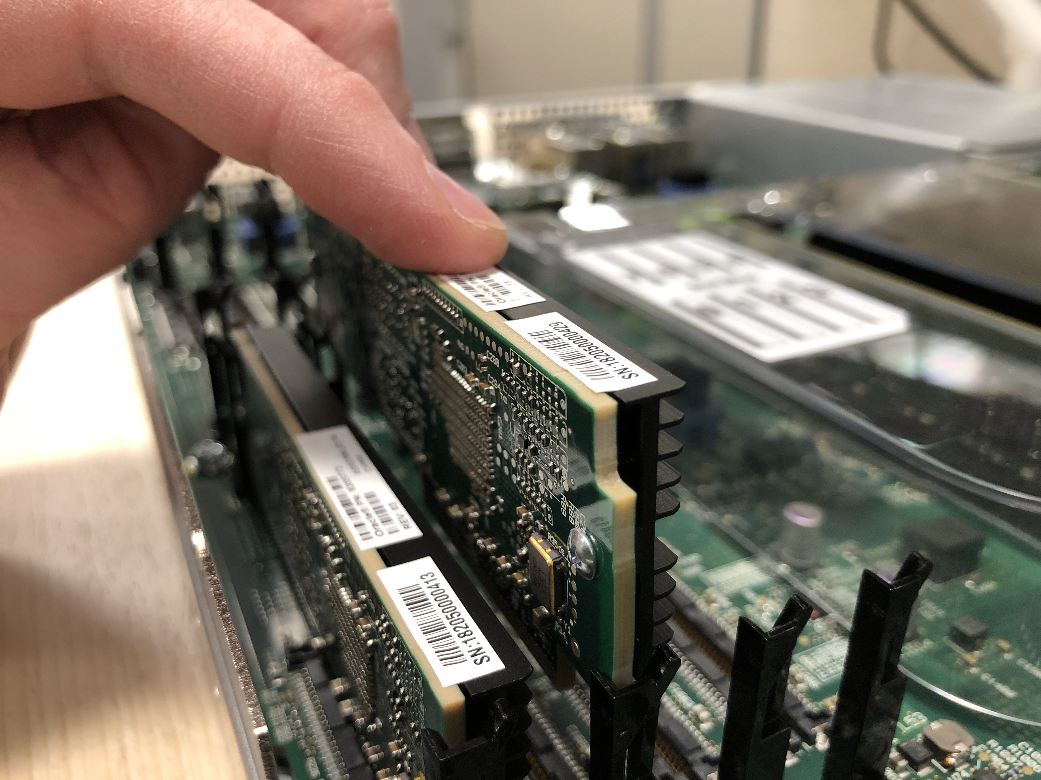
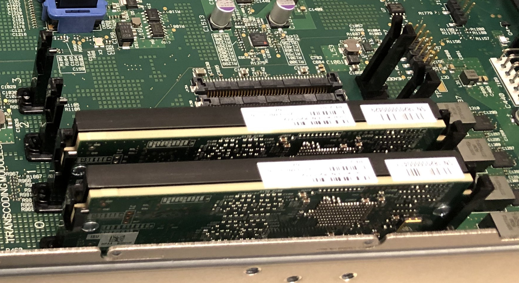
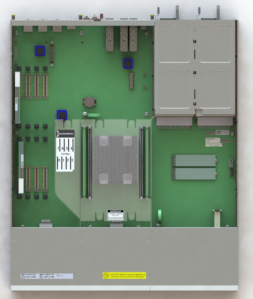
Up to 8 transcoder modules may be installed on the Acme Packet 4900 printed circuit board (PCB).
The Acme Packet 4900 PCB includes slots for installing the transcoder TCM modules. The slots are numbered 0-7. Slot 0 is in the bottom row and closest to the edge of the unit when looking at it from the front of the chassis. Transcoder TCM modules should be installed consecutively in numerical order, starting with slot 0.
Guidelines
- The transcoder module can be installed only in the designated location.
- Ground yourself and follow proper ESD grounding procedures.
- Remove the transcoder module from the shipped packaging.
- The installation of these modules should be performed during low-traffic periods or during times of scheduled maintenance.
- Follow industry-standard procedures to ensure ESD protection.
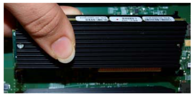
- When installing or removing a TCM module, move the card to an ESD-safe location.
Note:
Before handling any components, follow the proper ESD grounding procedures. Failure to do so could damage the card and its components.Required Parts
- ESD wrist strap
- ESD-safe location
- Transcoder TCM module
Removing and Replacing the T1/E1 Module
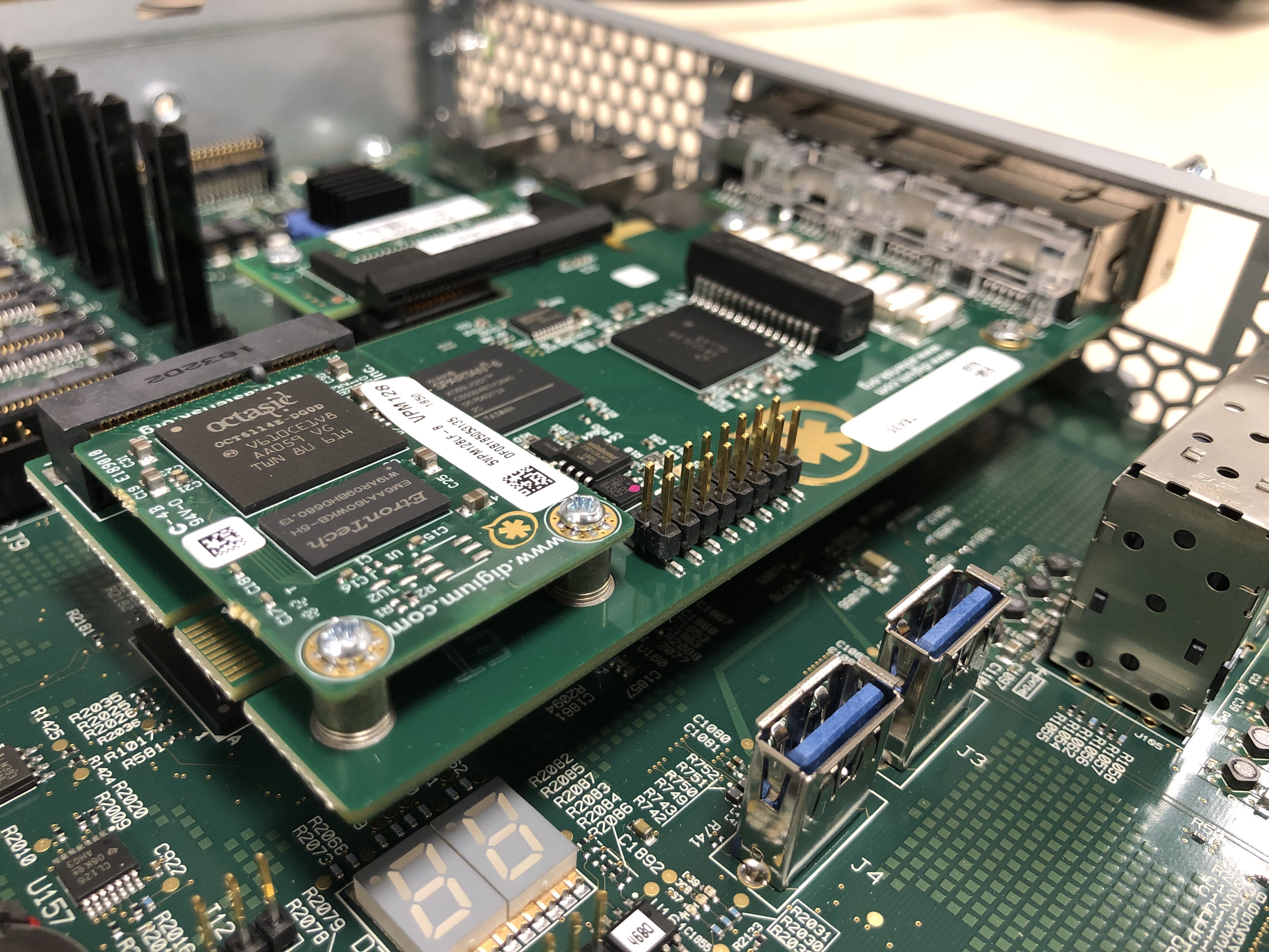
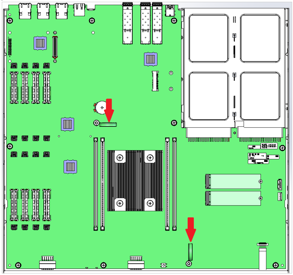
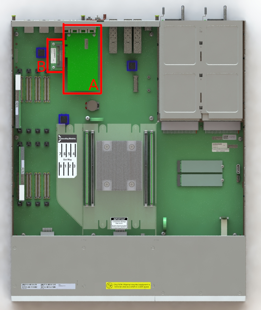
The T1/E1 module (A) is located near the rear of the board. It plugs into the rear panel as well as a raised PCI Express connector (B).

Guidelines
- Ground yourself and follow proper ESD grounding procedures.
- Remove the transcoder TDM module from the shipped packaging.
Note:
In the box with the new T1/E1 TDM modules, there will be aTelecom label in a plastic envelope. Attach the Telecom label to the chassis cover as described below.Note:
The installation of these modules should be performed during low-traffic periods or during times of scheduled maintenance.Caution:
Before handling any components, follow the proper ESD grounding procedures. Failure to do so could damage the card and its components.Required Parts
- ESD wrist strap
- ESD-safe location
- New or replacement TDM module
- Telecom label to attach to the chassis cover
Required BIOS and Software Upgrade
- RMA the device to Oracle.
- Upgrade to a software patch that supports the new card.
The following releases and newer support the Sangoma TDM card:
- 9.2p1
- 9.1p7
Install the TDM Module
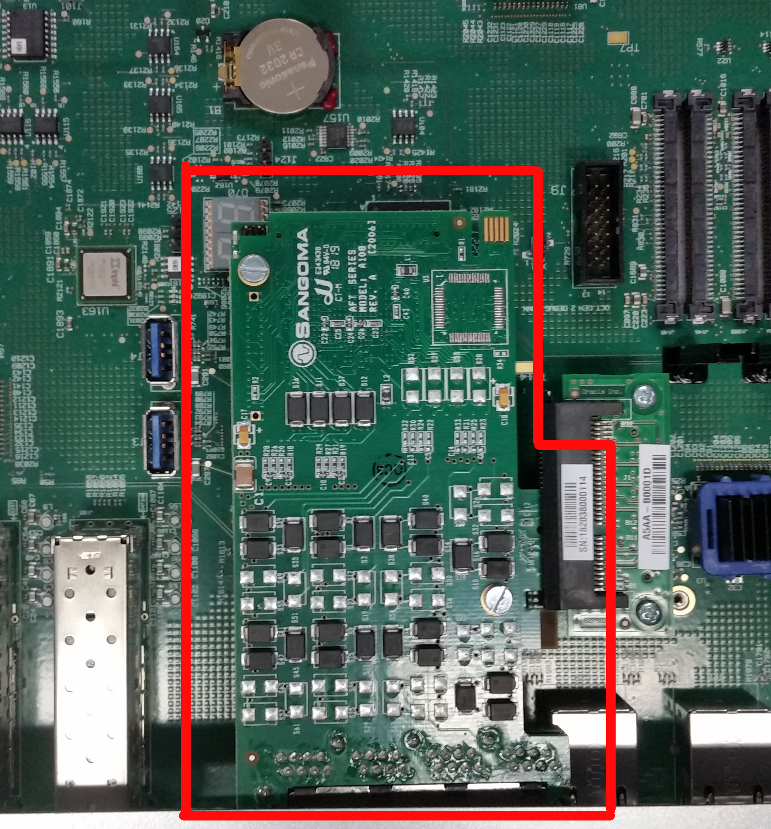
If you returned your device to Oracle to replace a Digium TDM card with a Sangoma TDM card, the new port numbers are reversed. So port number 1 on the Digium card is now port 4 on the Sangoma card. Use show tdm spans to view the span information.
Table 5-1 Port Numbers
| Digium port number | Sangoma port number |
|---|---|
| 1 | 4 |
| 2 | 3 |
| 3 | 2 |
| 4 | 1 |
