3 Preparing Your Networks for Recovery Appliance
This chapter describes the network requirements for Recovery Appliance, so that you can prepare your data center for installation.
This chapter contains the following sections:
Overview of Network Requirements
In addition to the compute and storage servers, Recovery Appliance includes equipment to connect the system to your network. The network connections allow clients to connect to the compute servers and also enables remote system administration.
Use the information in this section in conjunction with Oracle Exadata Deployment Assistant (OEDA) to configure your Recovery Appliance environment.
To deploy Recovery Appliance ensure that you meet the minimum network requirements. Recovery Appliance requires a minimum of three networks, and there are interfaces available for additional networks. Each network must be on a separate and distinct subnet. The network descriptions are as follows:
-
Administration Network: Also known as the management network, this required network connects to your existing management network infrastructure, and is used for administrative work on all components of Recovery Appliance. By default, the administration network connects the compute servers, storage servers, server Integrated Lights Out Manager (ILOM) interfaces, and RDMA Network Fabric switches to the Management Network Switch in the rack. One uplink is required from the Management Network Switch to your management network.
Each compute server and storage server has two network interfaces for administration. One interface provides management access to the operating system through a dedicated Ethernet port. The other network interface is dedicated to ILOM. By default, Recovery Appliance is delivered with both interfaces connected to the Management Network Switch. Cabling or configuration changes to these interfaces is not permitted, except that the ILOM interfaces can be connected to a dedicated ILOM network, which is separate from the administration network. The administration network interfaces on the compute servers should not be used for client or application network traffic.
Notes:
- Separate uplinks to your management network are also recommended for remote monitoring of each power distribution unit (PDU). This configuration enables you to easily differentiate between system outages caused by PDU failure as opposed to failure of the Management Network Switch.
- A properly secured configuration requires full isolation of the administration network from all other networks.
-
Ingest Network: This required network connects the protected Oracle Database servers to Recovery Appliance for backup within the same data center. Also known as a backup network, this high-speed, private Ethernet network must be designed to support the transfer of large volumes of data. Recovery Appliance connects to this network using two 10/25 GB connections to each of the two compute servers in the rack. You can configure the two connections as active/passive (redundant) or active/active.
The compute servers support channel bonding to provide higher bandwidth and availability.
Single client access name (SCAN) supports failover between the two compute servers in the Recovery Appliance. In an installation with multiple Recovery Appliance racks configured as a cluster, virtual IP (VIP) addresses support failover among the racks. The protected database systems can resolve the host names to dynamically assigned addresses.
Third-party tape hardware and software also uses the ingest network.
-
Private Network: Also known as the RDMA Network Fabric, storage network, or interconnect. This network connects the compute servers and storage servers. Oracle Database uses this network for Oracle RAC cluster interconnect traffic and for accessing data on the Oracle Exadata Storage Servers. The private network is automatically configured during installation. It is non-routable, fully contained in Recovery Appliance, and does not connect to your existing networks.
Starting with Recovery Appliance X8M, the private network uses RDMA over Converged Ethernet (RoCE).
Previously, the private network was built using InfiniBand technology. RoCE Network Fabric uses different switches and cables from those used by InfiniBand Network Fabric.
-
Replication network: The optional replication network uses available ports not used by the administration and the ingest network. It connects the local Recovery Appliance (the upstream appliance) with a remote Recovery Appliance (the downstream appliance). Oracle recommends a broadband, encrypted network, instead of an insecure public network, wherever possible.
Recovery Appliance supports the following configurations between the upstream and downstream appliances:
Note:
A downstream Recovery Appliance or a tape library can reside in the local data center. The replication network is not used in a local configuration.
The replication network must not be used for the purpose of ingesting backups.
-
Fiber Channel SAN network: If you are using Oracle Secure Backup, then you can back up Recovery Appliance to the storage area network (SAN) in your data center for backups to tape. The network connections depend on whether you have an Oracle tape solution or use third-party hardware.
Ingest and replication networks can be configured active/passive or active/active bonding.
-
Active / Passive Bonding - BONDING_OPTS=“mode=active-backup miimon=100 downdelay=2000 updelay=5000 num_grat_arp=100"
-
Active / Active Bonding - BONDING_OPTS="mode=802.3ad miimon=100 downdelay=200 updelay=200 lacp_rate=1 xmit_hash_policy=layer3+4"
Ingest can be Active/Active with Replication Active/Passive, or vice-versa. Or both can have the same bonding.
See Also:
-
Oracle Clusterware Administration and Deployment Guide for a discussion of SCANs and VIPs in network configurations for Oracle Database.
-
"Connecting Recovery Appliance to a Tape Library" for information about how a fibre channel SAN network is configured for backups to tape in a Recovery Appliance environment.
The following diagram displays how the various Recovery Appliance components connect to the different networks.
About the Network Components and Interfaces
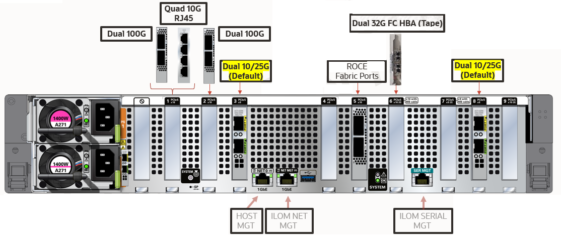
Each compute server in the RA23 configuration consists of the following network components and interfaces:
- 2 x Dual Port 10/25 Gb Ethernet SFP28
- 2 x 10/25 Gb optical (ingest)
- 2 x 10/25 Gb optical (replication)
- 2 x Dual Port 100 Gb Ethernet QSFP28
- 2 x 100 Gb optical (ingest)
- 2 x 100 Gb optical (replication)
- 1 x Quad Port 10 Gb Ethernet RJ45
- 2 x 10 Gb copper (ingest)
- 2 x 10 Gb copper (replication)
- For ingest network, maximum of
- 2 x 10 Gb Ports,
- 2 x 25 Gb Ports, or
- 2 x 100 Gb Ports
- For replication network, maximum of
- 2 x 10 Gb Ports,
- 2 x 25 Gb Ports, or
- 2 x 100 Gb Ports
- Ingest and Replication can be different, for example 100Gb for ingest and 25Gb for replication.
- Optional Ports
- Sun Storage Dual 32 Gb Fibre Channel PCIe Universal HBA, QLogic for tape connectivity
- Standard Ports
- 2 x 100 Gb QSFP28 RoCE Fabric Ports
- 1 x 1 Gb copper Ethernet Port (mgmt)
- 1 x ILOM Ethernet Port
Figure 3-1 Oracle Zero Data Loss Recovery Appliance RA23 Networking
Each compute server in the RA21 configuration consists of the following network components and interfaces:
-
Ethernet ingest and replication network connectivity, :
-
2 x Dual 10/25G Network Cards, or
-
2 x Quad 10G Network Cards, or
-
1 x Quad 10G Network Card and 1 x Dual 10/25G Network Card
-
-
2 x QSFP2B RoCE Fabric Ports
-
1 Ethernet port for
Serial MGTremote management -
1 Ethernet port for
ILOM MGT(Oracle Integrated Lights Out Manager) remote management -
1 Ethernet port for
HOST MGTremote management -
Optional: Dual 32G HBA (Tape) card that can be field installed. This slot is not available for other network cards.
Figure 3-2 Oracle Zero Data Loss Recovery Appliance RA21 Backplane External Network Connectivity
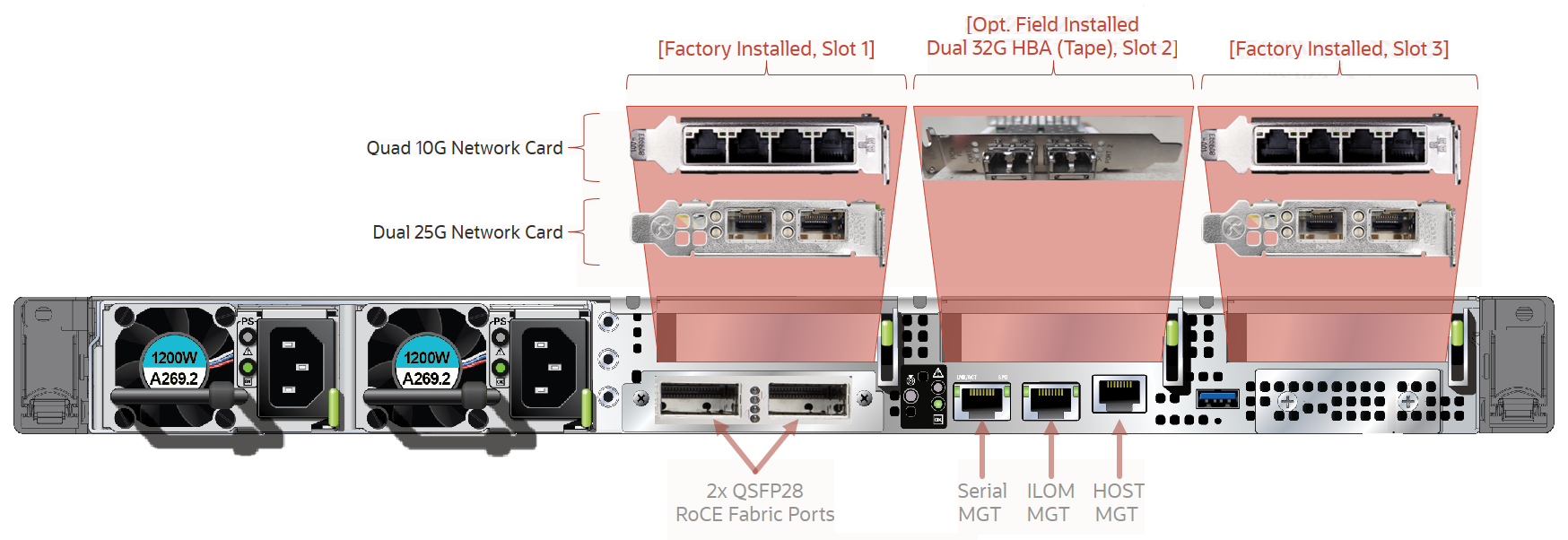
Description of "Figure 3-2 Oracle Zero Data Loss Recovery Appliance RA21 Backplane External Network Connectivity"
- Maximum of two 10G (or 25G) ports for ingest and two 10G (or 25G) ports for replication, per compute server
- Maximum of four 10G (or 25G) for each network in bonded LACP configuration, per rack
- Replication can be used as separate ingest network (MOS Note 2126047.1)
- VLAN tagging supported on ingest network (MOS Note 2047411.1)
- Slot 2 cannot be used for additional network card.
Each compute server in the X8M configuration consists of the following network components and interfaces:
-
Ethernet ingest and replication network connectivity, :
-
2 x Dual 10/25G Network Cards, or
-
2 x Quad 10G Network Cards, or
-
1 x Quad 10G Network Card and 1 x Dual 10/25G Network Card
-
-
2 x QSFP2B RoCE Fabric Ports
-
1 Ethernet port for
Serial MGTremote management -
1 Ethernet port for
ILOM MGT(Oracle Integrated Lights Out Manager) remote management -
1 Ethernet port for
HOST MGTremote management -
Optional: Dual 32G HBA (Tape) card that can be field installed. This slot is not available for other network cards.
Figure 3-3 Oracle Zero Data Loss Recovery Appliance X8M Backplane External Network Connectivity

Description of "Figure 3-3 Oracle Zero Data Loss Recovery Appliance X8M Backplane External Network Connectivity"
- Maximum of two 25G ports for ingest and two 25G ports for replication, per compute server
Each compute server in the X8-2 and X7 configuration consists of the following network components and interfaces:
-
Ethernet ingest and replication network connectivity
-
On-board: 2 x 10 Gb copper Ethernet (eth1)
-
On-board: 2 x 10/25 Gb optical Ethernet Ports (eth2)
-
PCIe card: 2 x 10/25 Gb optical Ethernet Ports (eth3 and eth4)
-
-
1 dual-port 4X QDR (40 Gbps) InfiniBand Host Channel Adapter (HCA) (IB0 and IB1)
-
1 Ethernet port for Oracle Integrated Lights Out Manager (ILOM) remote management
-
1 dual-port 32 GB FC Converged Network Adapter (CNA) FC ports 0 and 1.
Note:
The corresponding SFP modules that work with the 10/25 GbE PCIe 2.0 network cards are purchased separately.
Figure 3-4 Oracle Zero Data Loss Recovery Appliance X8-2 and X7 Backplane External Network Connectivity
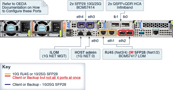
Description of "Figure 3-4 Oracle Zero Data Loss Recovery Appliance X8-2 and X7 Backplane External Network Connectivity"
Given that the base rack has two (2) compute servers, the maximum for ingest is 2 x 10 Gb or 2 x 25 Gb Ethernet ports, while the maximum for replication is 2 x 10 Gb or 2 x 25 Gb Ethernet ports. The following are valid combinations of the options.
-
2 x 10Gb on-board copper (ingest) + 2 x 10/25Gb PCIe card optical (replication)
-
2 x 10/25Gb PCIe card optical (ingest) + 2 x 10Gb on-board copper (replication)
-
2 x 10/25Gb PCIe card optical (ingest) + 2 x 10/25Gb on-board optical (replication)
-
2 x 10/25Gb on-board optical (ingest) + 2 x 10/25Gb PCIe card optical (replication)
Note:
If ingest and replication traffic is desired to be configured on the same network, define the required network interface in OEDA in the ingest network section, and leave the replication network section blank. With this setup, Recovery Appliance will use the ingest network for replication traffic.Each storage server consists of the following network components and interfaces:
-
1 embedded Gigabit Ethernet port (NET0)
-
1 dual-port 4X QDR (40 Gbps) InfiniBand Host Channel Adapter (HCA) (IB0 and IB1)
-
1 Ethernet port for Oracle Integrated Lights Out Manager remote management (Oracle ILOM)
Additional configuration, such as defining multiple virtual local area networks (VLANs) for the management (NET0 and/or ILOM) interfaces or enabling routing, might be required for the switch to operate properly in your environment and is beyond the scope of the installation service. If additional configuration is needed, then your network administrator must perform the necessary configuration steps during installation of Recovery Appliance.
Example of Network Connections for Recovery Appliance
Figure 3-5 shows the network cabling of a sample configuration. Two Recovery Appliance racks are installed in separate data centers. The protected Oracle databases are connected to the upstream Recovery Appliance over the ingest network. The upstream Recovery Appliance is connected to the downstream Recovery Appliance over the replication network. Both racks are configured to use an Oracle tape solution.
Figure 3-5 Network Diagram for Recovery Appliance
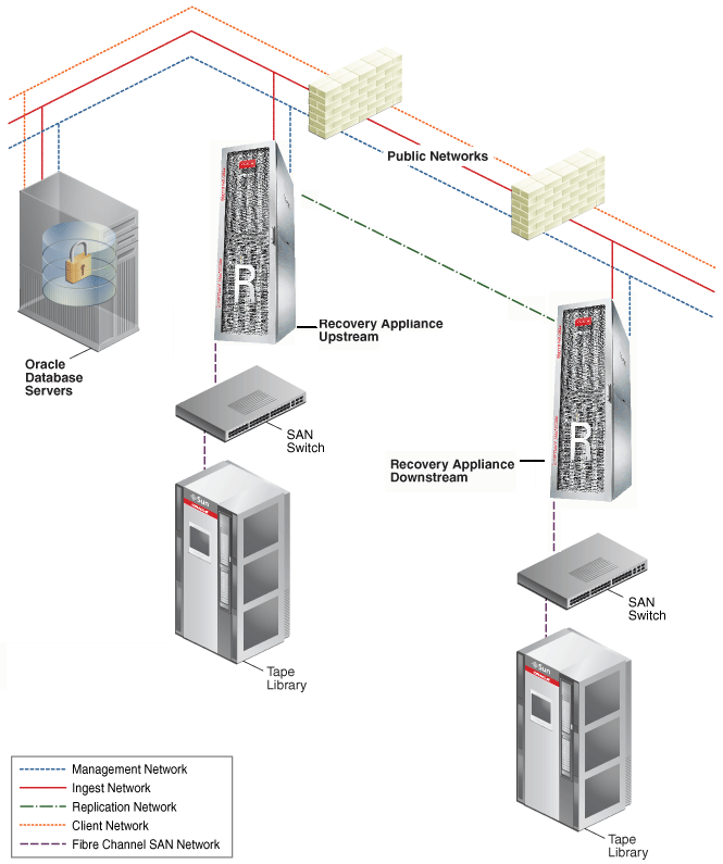
Description of "Figure 3-5 Network Diagram for Recovery Appliance"
Connecting Recovery Appliance Rack Components to the Networks
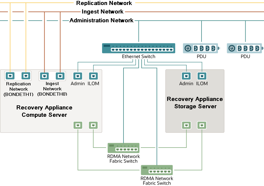
Figure 3-6 shows the network connections to components of Recovery Appliance rack.
The management network connects through the Ethernet switch to the compute servers, the storage servers, and the RDMA Network Fabric switches. The management network connects directly to the PDUs.
The ingest network, the optional replication network, and the optional fiber channel SAN network connect to the two compute servers.
The RDMA Network Fabric network connects the switches to the compute servers and the storage servers.
Figure 3-6 Network Connections to the Recovery Appliance Rack Components
Description of "Figure 3-6 Network Connections to the Recovery Appliance Rack Components"
Connecting Recovery Appliance to a Tape Library
The network connections between Recovery Appliance and an optional tape library depend on whether you are using Oracle or third-party tape management system. See "About Tape Backup Infrastructure" for the differences in support provided by Recovery Appliance.
Oracle Recommended Stack
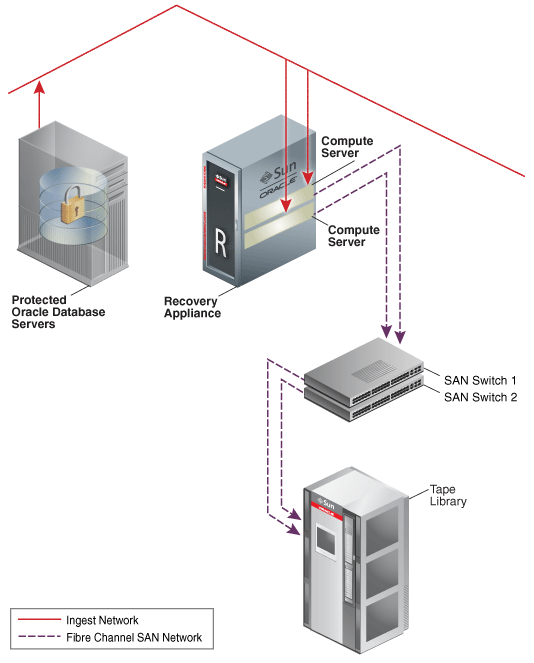
When you use the Oracle compatible tape solution, a fiber channel adapter is installed in each compute server to provide a connection to the fiber channel storage area network (SAN). Tape backups are isolated on this network, and thus do not interfere with the performance of the other networks. Figure 3-7 provides an overview of the network connections when using an Oracle tape system.
Figure 3-7 Recovery Appliance Connection to an Oracle Tape System
Description of "Figure 3-7 Recovery Appliance Connection to an Oracle Tape System"
Third-Party Tape Systems
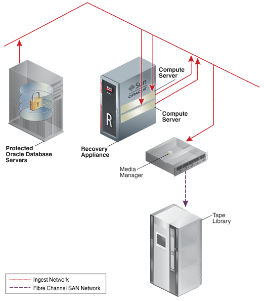
When you use a third-party tape system, the backups to tape use the ingest network. This is the same network that the local protected databases use to backup to Recovery Appliance. Figure 3-8 provides an overview of the network connections when using a third-party tape system.
Figure 3-8 Recovery Appliance Connection to a Third-Party Tape System
Description of "Figure 3-8 Recovery Appliance Connection to a Third-Party Tape System"
Using Network VLAN Tagging with Recovery Appliance
The Recovery Appliance supports VLAN port tagging only on the ingest network. You configure VLAN port tagging after you complete the Recovery Appliance installation.
If applicable, ensure that you also set the Access VLAN on the network switches, including on the Cisco switch that is included in the Recovery Appliance rack for the management network.
See Also:
"Installing the Software on Recovery Appliance" for instructions on when and how to configure VLAN tagging
Registering Recovery Appliance in the Domain Name System
Before receiving your Recovery Appliance rack, use Oracle Exadata Deployment Assistant. The assistant generates a file to be used when setting up the system. The host names and IP addresses specified in the assistant-generated file must be registered in Domain Name System (DNS) before the initial configuration. In addition, all public addresses, single client access name (SCAN) addresses, and VIP addresses must be registered in DNS before installation.
The assistant-generated file defines the SCAN as a single name with three IP addresses on the client access network. The three SCAN addresses provide service access for clients to Recovery Appliance. Configure DNS for round robin resolution for the SCAN name to these three SCAN addresses.
All addresses registered in DNS must be configured for both forward resolution and reverse resolution. Reverse resolution must be forward confirmed (forward-confirmed reverse DNS) such that both the forward and reverse DNS entries match each other.
See Also:
-
Oracle Grid Infrastructure Installation Guide for Linux for additional information about SCAN addresses
-
Your DNS vendor documentation for additional information about configuring round-robin name resolution
Factory IP Address Settings
Recovery Appliance has default IP addresses set at the factory:
-
Gateway: 192.168.1.254 in all devices as required
-
Subnet Mask: 255.255.252.0 in all devices as required
-
IP Address Range: 192.168.1.1 to 192.168.1.203
Before connecting Recovery Appliance to the network, ensure that these IP addresses do not conflict with other addresses on the network. The checkip.sh script checks for conflicts. Oracle recommends running the script before connecting the network to avoid problems, even when a check was performed before Recovery Appliance was delivered. See "Installing the Software on Recovery Appliance" for additional information about the checkip.sh script.
Table 3-1 lists the factory IP addresses for a Recovery Appliance full rack.
Table 3-1 Factory IP Addresses for Recovery Appliance
| Rack Unit | Component | Management Network Addresses | InfiniBand Active Bonded IP Addresses | Oracle ILOM IP Addresses |
|---|---|---|---|---|
|
U41 |
Storage server |
192.168.1.23 |
192.168.10.45 |
192.168.1.123 |
|
U39 |
Storage server |
192.168.1.22 |
192.168.1.43 |
192.168.1.122 |
|
U37 |
Storage server |
192.168.1.21 |
192.168.10.41 |
192.168.1.121 |
|
U35 |
Storage server |
192.168.1.20 |
192.168.10.39 |
192.168.1.120 |
|
U33 |
Storage server |
192.168.1.19 |
192.168.10.37 |
192.168.1.119 |
|
U31 |
Storage server |
192.168.1.18 |
192.168.10.35 |
192.168.1.118 |
|
U29 |
Storage server |
192.168.1.17 |
192.168.10.33 |
192.168.1.117 |
|
U27 |
Storage server |
192.168.1.16 |
192.168.10.31 |
192.168.1.116 |
|
U25 |
Storage server |
192.168.1.14 |
192.168.10.27 |
192.168.1.114 |
|
U23 |
Storage server |
192.168.1.12 |
192.168.10.23 |
192.168.1.112 |
|
U22 |
RDMA Network Fabric switch |
Not applicable |
Not applicable |
192.168.1.203 |
|
U21 |
Ethernet switch |
Not applicable |
Not applicable |
192.168.1.200 |
|
U20 |
RDMA Network Fabric switch |
Not applicable |
Not applicable |
192.168.1.202 |
|
U18 |
Storage server |
192.168.1.10 |
192.168.10.19 |
192.168.1.110 |
|
U17 |
Compute server |
192.168.1.9 |
192.168.10.17 |
192.168.1.109 |
|
U16 |
Compute server |
192.168.1.8 |
192.168.10.15 |
192.168.1.108 |
|
U14 |
Storage server |
192.168.1.7 |
192.168.10.13 |
192.168.1.107 |
|
U12 |
Storage server |
192.168.1.6 |
192.168.10.11 |
192.168.1.106 |
|
U10 |
Storage server |
192.168.1.5 |
192.168.10.9 |
192.168.1.105 |
|
U08 |
Storage server |
192.168.1.4 |
192.168.10.7 |
192.168.1.104 |
|
U06 |
Storage server |
192.168.1.3 |
192.168.10.5 |
192.168.1.103 |
|
U04 |
Storage server |
192.168.1.2 |
192.168.10.3 |
192.168.1.102 |
|
U02 |
Storage server |
192.168.1.1 |
192.168.10.1 |
192.168.1.101 |
Port Assignments When Using a Firewall
When network communication between Recovery Appliance and other components requires access through a firewall, you must open ports used by the Recovery Appliance services.
Note:
A firewall may not be used between components of the Recovery Appliance.
Table 3-2 lists the ports used by services on Recovery Appliance. Review the list and open the necessary ports. All ports are on the management network, unless otherwise noted.
Table 3-2 Open Ports for the Firewall
| Source | Target | Protocol | Port | Application |
|---|---|---|---|---|
|
NA |
Database management |
SSH over TCP |
22 |
SSH |
|
NA |
Compute servers, storage servers, and InfiniBand ILOMs |
SSH over TCP |
22 |
SSH |
|
NA |
Storage management |
SSH over TCP |
22 |
SSH |
|
Storage servers |
email server |
SMTP |
25 465 if using SSL |
SMTP (Simple Mail Transfer Protocol) |
|
Compute servers, storage servers, and InfiniBand ILOMs |
NA |
TFTP over UDP |
69 |
Outgoing TFTP (Trivial File Transfer Protocol) |
|
NA |
Compute servers, storage servers, and InfiniBand ILOMs |
HTTP over TCP |
80 |
Web (user configurable) |
|
NA |
PDU |
HTTP over TCP |
80 |
Browser interface |
|
Database management |
NA |
NTP over UDP |
123 |
Outgoing Network Time Protocol (NTP) |
|
Compute servers, storage servers, and InfiniBand ILOMs |
NA |
NTP over UDP |
123 |
Outgoing NTP |
|
Storage management |
NA |
NTP over UDP |
123 |
Outgoing NTP |
|
ASR Manager |
ASR asset |
SNMP (get) |
161 |
FMA enrichment for additional diagnostic information |
|
NA |
Compute servers, storage servers, and InfiniBand ILOMs |
SNMP over UDP |
161 |
SNMP (Simple Network Management Protocol) (user configurable) |
|
NA |
PDU |
SNMP over UDP |
161 |
SNMP (user configurable) |
|
Storage servers |
SNMP subscriber such as Oracle Enterprise Manager Cloud Control or an SNMP manager |
SNMP |
162 |
SNMP version 1 (SNMPv1) outgoing traps (user-configurable) |
|
Compute servers and storage server ILOMs |
ASR Manager |
SNMP |
162 |
Telemetry messages sent to ASR Manager |
|
Compute servers, storage servers, and InfiniBand ILOMs |
NA |
IPMI over UDP |
162 |
Outgoing IPMI (Intelligent Platform Management Interface) Platform Event Trap (PET) |
|
PDU |
NA |
SNMP over UDP |
162 |
Outgoing SNMPv2 traps |
|
NA |
Compute servers, storage servers, and InfiniBand ILOMs |
LDAP over UDP/TCP |
389 |
Outgoing LDAP (Lightweight Directory Access Protocol) (user configurable) |
|
ASR Manager |
ASR back end |
HTTPS |
443 |
Telemetry messages sent to ASR back end |
|
NA |
Compute servers, storage servers, and InfiniBand ILOMs |
HTTPS over TCP |
443 |
Web (user configurable) |
|
NA |
PDU |
HTTPS over TCP |
443 |
Browser interface |
|
Compute servers, storage servers, and InfiniBand ILOMs |
NA |
Syslog over UDP |
514 |
Outgoing Syslog |
|
PDU |
NA |
Syslog over UDP |
514 |
Outgoing Syslog |
|
Compute servers, storage servers, and InfiniBand ILOMs |
NA |
DHCP over UDP |
546 |
client DHCP (Dynamic Host Configuration Protocol) |
|
PDU |
NA |
DHCP over UDP |
546 |
DHCP (Dynamic Host Configuration Protocol) client |
|
NA |
Compute servers, storage servers, and InfiniBand ILOMs |
IPMI over UDP |
623 |
IPMI (Intelligent Platform Management Interface) |
|
Oracle Enterprise Manager Cloud Control |
NA |
TCP |
1159 |
Oracle Enterprise Manager Cloud Control HTTPS upload port |
|
Oracle Enterprise Manager Cloud Control |
NA |
TCP |
1159 |
Oracle Enterprise Manager Cloud Control HTTPS upload port |
|
NA |
Database data |
SQL*Net over TCP |
1521 |
Database listener |
|
Protected database |
Recovery Appliance |
SQL*Net over TCP |
1521 (ingest network) |
RMAN backup and restore |
|
Upstream Recovery Appliance |
Downstream Recovery Appliance |
SQL*Net over TCP |
1522 (replication network) |
Recovery Appliance Replication |
|
Compute servers, storage servers, and InfiniBand ILOMs |
NA |
RADIUS over UDP |
1812 |
Outgoing RADIUS (Remote Authentication Dial In User Service) (user configurable) |
|
Oracle Enterprise Manager Grid Control |
NA |
TCP |
4889 |
Oracle Enterprise Manager Cloud Control HTTP upload port |
|
Oracle Enterprise Manager Grid Control |
NA |
TCP |
4889 |
Oracle Enterprise Manager Cloud Control HTTP upload port |
|
NA |
Compute server and storage server ILOMs |
TCP |
5120 |
ILOM remote console: CD |
|
NA |
Compute server and storage server ILOMs |
TCP |
5121 |
ILOM remote console: keyboard and mouse |
|
NA |
Compute server and storage server ILOMs |
TCP |
5123 |
ILOM remote console: diskette |
|
NA |
Compute server and storage server ILOMs |
TCP |
5555 |
ILOM remote console: encryption |
|
NA |
Compute server and storage server ILOMs |
TCP |
5556 |
ILOM remote console: authentication |
|
ASR Manager |
Compute server and storage server ILOMs |
HTTP |
6481 |
Service tags listener for asset activation |
|
NA |
Compute server and storage server ILOMs |
TCP |
6481 |
ILOM remote console: |
|
NA |
Compute server and storage server ILOMs |
TCP |
7578 |
ILOM remote console: video |
|
NA |
Compute server and storage server ILOMs |
TCP |
7579 |
ILOM remote console: serial |
|
NA |
Compute servers |
TCP |
7777 |
Oracle Enterprise Manager Grid Control HTTP console port |
|
NA |
Storage servers |
TCP |
7777 |
Oracle Enterprise Manager Grid Control HTTP console port |
|
NA |
Compute servers |
TCP |
7799 |
Oracle Enterprise Manager Grid Control HTTPS console port |
|
NA |
Storage servers |
TCP |
7799 |
Oracle Enterprise Manager Grid Control HTTPS console port |
|
Protected database |
Recovery Appliance |
HTTP |
8001 (ingest network) |
RMAN backup and restore |
|
Upstream Recovery Appliance |
Downstream Recovery Appliance |
HTTP |
8001 (replication network) |
Recovery Appliance Replication |