Processor Overview
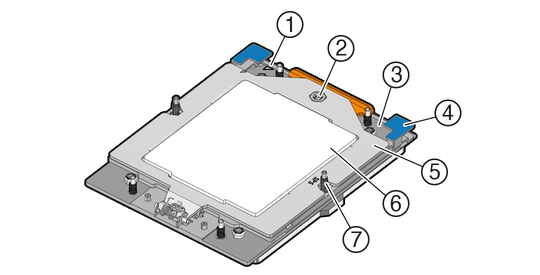
Socket components in the processor assembly have a pin 1 indicator to aid in assembly.

| Callout | Description |
|---|---|
|
1 |
Pin 1 orientation |
|
2 |
Force Frame Retention Screw (captive) |
|
3 |
Rail Frame (socket stiffener frame) |
|
4 |
Release Tabs (2x) |
|
5 |
Force Frame (retention frame) |
|
6 |
Processor Package (carrier frame holding preinstalled processor) |
|
7 |
Heatsink Attachment Studs (6x) |
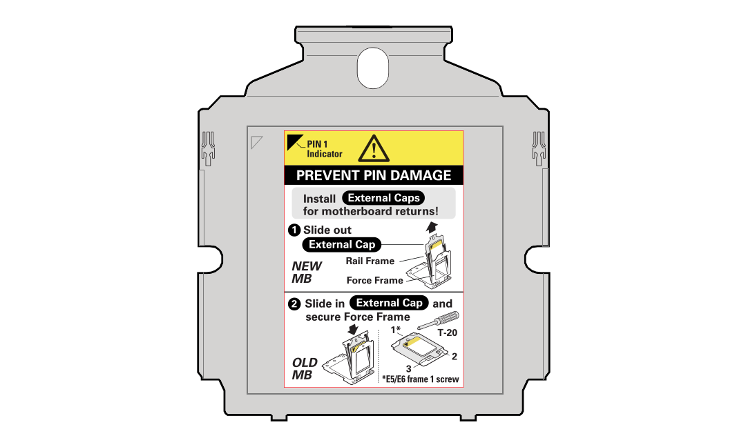
External Cap
The external cap is used to protect the socket pins if the processor is not installed. The following figure shows the External Cap.
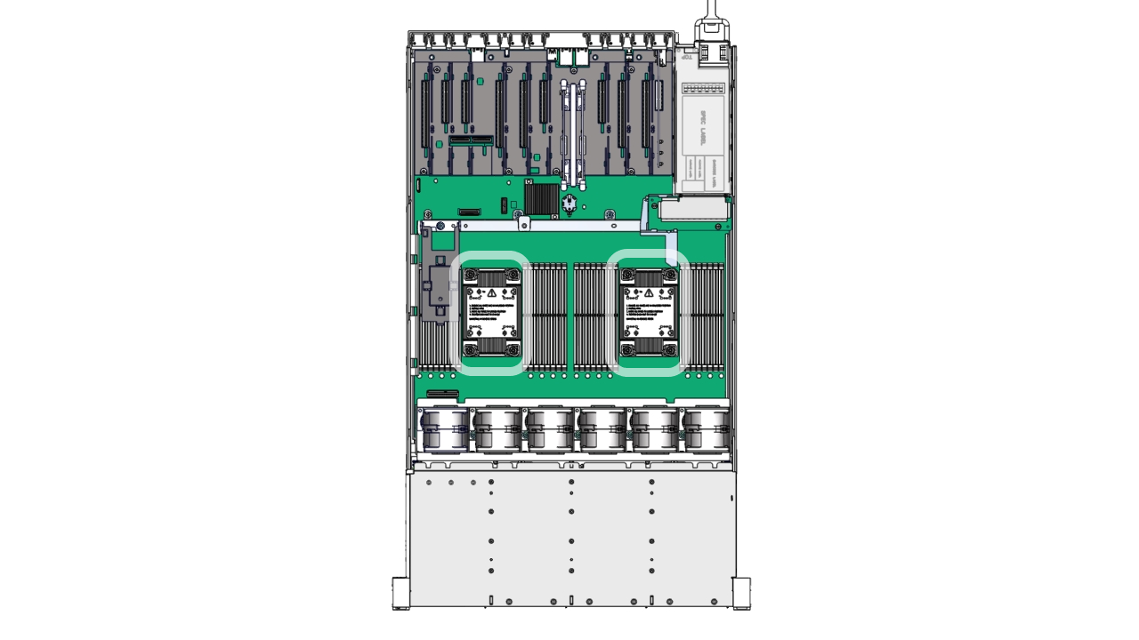
Two processor sockets are located on the server motherboard.
