2 Overview of Oracle Database Appliance
Learn about Oracle Database Appliance model supported components,capabilities and features.
- Oracle Database Appliance X9-2 Series Components and Capabilities
See a listing of the various supported capabilities for the Oracle Database Appliance X9-2 series. - Oracle Database Appliance X9-2S/X9-2L Front and Back Panels
See views and descriptions of front and back panel features for Oracle Database Appliance X9-2S/X9-2L. - Oracle Database Appliance X9-2-HA Front and Back Panels
See views and descriptions of front and back panel features for Oracle Database Appliance X9-2-HA. - Oracle Database Appliance Specifications
This section describes the physical, electrical and environmental specifications for the various Oracle Database Appliance models. - Technical Support
How to obtain technical support for your appliance.
Oracle Database Appliance X9-2 Series Components and Capabilities
See a listing of the various supported capabilities for the Oracle Database Appliance X9-2 series.
The following table lists supported components and capabilities for the Oracle Database Appliance X9-2 series systems.
| Component | Oracle Database Appliance X9-2S | Oracle Database Appliance X9-2L | Oracle Database Appliance X9-2-HA |
|---|---|---|---|
|
Server node |
Single 2RU server. |
Single 2RU server. |
Two 2RU server nodes. Each server node operates independently from the other server node. The lower server is node 0. The upper server is node 1. |
|
CPUs |
One 16-core 2.4 GHz Intel Xeon S4314 processor. |
Two 16-core 2.4 GHz Intel Xeon S4314 processors. |
Two 16-core 2.4 GHz Intel Xeon S4314 processors per server node. |
|
Memory |
256 GB – eight 32 GB low-voltage DDR4 RDIMMs rated at 3200 MT/sec. Optional memory expansion to 512 GB. See Optional Component Installation. |
512 GB – sixteen 32 GB low-voltage DDR4 RDIMMs rated at 3200 MT/sec. Optional memory expansion is available to 1 TB. See Optional Component Installation. |
512 GB – sixteen 32 GB low-voltage DDR4 RDIMMs rated at 3200 MT/sec per server node. Optional memory expansion to 1 TB per node. Both server nodes must have the same amount of memory. See Optional Component Installation. |
|
Storage devices |
The server includes:
No additional storage options are supported. |
The server includes:
Up to ten optional NVMe SSDs can be added. See Optional Component Installation. |
Each server node includes:
The 4RU storage shelf includes one of the following available configurations:
For a partially populated storage shelf, optional 7.68 TB SAS SSDs, or 18 TB SAS HDDs can be added. See Optional Component Installation. |
|
USB 3.0 ports |
One external port at the back of the server. |
One external port at the back of the server. |
One external port at the back of each server node. |
|
PCI Express (PCIe) I/O slots |
Ten external low-profile PCIe Gen-4 slots. In the base configuration: PCIe slot 6 contains one of the following:
Additional option card configurations can be ordered. See Optional Component Installation. |
Ten external low-profile PCIe Gen-4 slots. In the base configuration: PCIe slot 6 contains one of the following:
PCIe slot 10 contains an Oracle Retimer Card. Additional option card configurations can be ordered. See Optional Component Installation. |
Ten external low-profile PCIe Gen-4 slots for each server node. In the base configuration: PCIe slot 1 contains a Dual Port (SFP28) 25 Gb Ethernet Adapter (node interconnect) PCIe slot 6 contains one of the following:
PCIe slots 2 and 9 contain a Dual-port External 12Gb/s SAS3 host bus adapter Additional option card configurations can be ordered. See Optional Component Installation. |
|
Cluster device |
N/A |
N/A |
One integrated cluster device with node-to-node interconnection is provided on each server node through two 25GbE ports with SFP28 connections. |
|
SAS ports |
N/A |
N/A |
Four external SAS3 ports on each server node. Eight SAS3 ports on the storage shelf (four used). Eight SAS3 ports on the storage expansion shelf (four used). |
|
Onboard Ethernet ports |
One 10/100/1000Base-T network interface port with RJ-45 connector on each server rear panel. |
One 10/100/1000Base-T network interface port with RJ-45 connector on each server rear panel. |
One 10/100/1000Base-T network interface port with RJ-45 connector on each server node rear panel. |
|
Network management (NET MGT) port |
One 10/100/1000Base-T network interface port with RJ-45 connector dedicated to the service processor (SP) on each server node rear panel. |
One 10/100/1000Base-T network interface port with RJ-45 connector dedicated to the service processor (SP) on each server node rear panel. |
One 10/100/1000Base-T network interface port with RJ-45 connector dedicated to the service processor (SP) on each server node rear panel. |
|
Serial management (SER MGT) port |
One RS-232 RJ-45 serial port on each server rear panel. |
One RS-232 RJ-45 serial port on each server rear panel. |
One RS-232 RJ-45 serial port on each server node rear panel. |
|
VGA port |
N/A |
N/A |
N/A |
|
Service Processor (SP) |
Each server has a service processor with the following features:
|
Each server has a service processor with the following features:
|
Each server node has a service processor with the following features:
|
|
Power supplies |
Two A269.2 1200W or two A271/A271A 1400W power supplies are included in the base configuration. Power supplies for the system are redundant (N+N) and hot-pluggable. Systems with A269.2 power supplies can use 100 - 127 or 200 - 240 VAC sources. Systems with A271/A271A power supplies require high-line 200 - 240 VAC sources. Note: Mixing A269.2 and A271/A271A power supplies within the same chassis is not supported. |
Two A269.2 1200W or two A271/A271A 1400W power supplies are included in the base configuration. Power supplies for the system are redundant (N+N) and hot-pluggable. Systems with A269.2 power supplies can use 100 - 127 or 200 - 240 VAC sources. Systems with A271/A271A power supplies require high-line 200 - 240 VAC sources. Note: Mixing A269.2 and A271/A271A power supplies within the same chassis is not supported. |
Two hot-pluggable power supplies per server node and per storage shelf. The server node includes A269.2 1200W or two A271/A271A 1400W power supplies in the base configuration. Power supplies for the system are redundant (N+N) and hot-pluggable. Systems with A269.2 power supplies can use 100 - 127 or 200 - 240 VAC sources. Systems with A271/A271A power supplies require high-line 200 - 240 VAC sources. Note: Mixing A269.2 and A271/A271A power supplies within the same chassis is not supported.The DE3-24C storage shelf can use 100 - 127 or 200 - 240 VAC sources |
|
Cooling fans |
Four 80-mm, hot-pluggable fan modules per server for chassis cooling. Each fan module contains two counter-rotating fan pairs (four rotors total). Each power supply has its own cooling fans. |
Four 80-mm, hot-pluggable fan modules per server for chassis cooling. Each fan module contains two counter-rotating fan pairs (four rotors total). Each power supply has its own cooling fans. |
Four 80-mm, hot-pluggable fan modules per server node for chassis cooling. Each fan module contains two counter-rotating fan pairs (four rotors total). Each power supply (server node and storage shelf) has its own cooling fans. |
|
Operating system |
Oracle Linux. |
Oracle Linux. |
Oracle Linux. |
|
Management software |
Oracle Integrated Lights Out Manager (ILOM) 5.1. |
Oracle Integrated Lights Out Manager (ILOM) 5.1. |
Oracle Integrated Lights Out Manager (ILOM) 5.1. |
Parent topic: Overview of Oracle Database Appliance
Oracle Database Appliance X9-2S/X9-2L Front and Back Panels
See views and descriptions of front and back panel features for Oracle Database Appliance X9-2S/X9-2L.
This section describes Oracle Database Appliance X9-2S/X9-2L front and back panels. If you have some other Oracle Database Appliance model, select the appropriate link listed in Overview of Oracle Database Appliance.
- Oracle Database Appliance X9-2S/X9-2L Front Panel
See an illustration and description of Oracle Database Appliance X9-2S/X9-2L front panel features. - Oracle Database Appliance X9-2S/X9-2L Back Panel
See an illustration and description of Oracle Database Appliance X9-2S/X9-2L back panel features.
Parent topic: Overview of Oracle Database Appliance
Oracle Database Appliance X9-2S/X9-2L Front Panel
See an illustration and description of Oracle Database Appliance X9-2S/X9-2L front panel features.
Oracle Database Appliance X9-2S and Oracle Database Appliance X9-2L servers each occupy 2RU.
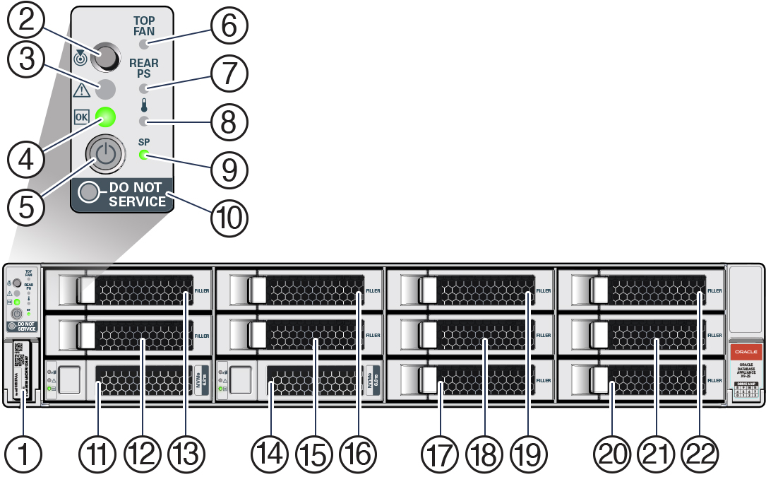
The following figure shows the components on the front panel of a standard configuration Oracle Database Appliance X9-2S/X9-2L.
| Callout | Description |
|---|---|
|
1 |
Product Serial Number (PSN) label and Radio Frequency Identification (RFID) tag |
|
2 |
Locate LED/button: white |
|
3 |
Service Required LED: amber |
|
4 |
Power/OK LED: green |
|
5 |
Power button |
|
6 |
Fan Fault LED: amber |
|
7 |
Power Supply (PS) Fault LED: amber |
|
8 |
System Over Temperature Warning LED: amber |
|
9 |
SP OK LED: green |
|
10 |
DO NOT SERVICE |
|
11 - 22 |
Front mounted drive slots: NVMe0 in slot 0 (callout 11), NVMe1 in slot 1 (callout 14), filler panels in slots 2 - 11 (callouts 12, 13 and 15 - 22) |
Oracle Database Appliance X9-2S/X9-2L Back Panel
See an illustration and description of Oracle Database Appliance X9-2S/X9-2L back panel features.
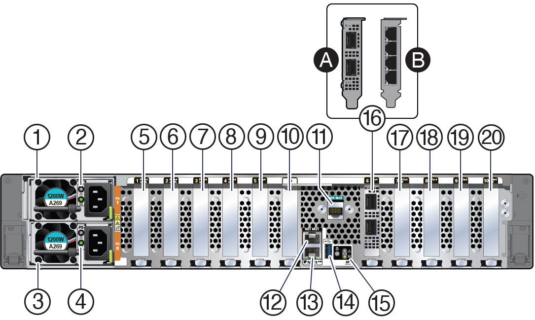
The following figure shows the components on the back panel of an Oracle Database Appliance X9-2S/X9-2L.
| Callout | Description |
|---|---|
|
1 |
Power Supply (PS) 1 with fan module |
|
2 |
Power Supply (PS) 1 status indicators: Service Required LED: amber, AC OK LED: green |
|
3 |
Power Supply (PS) 0 with fan module |
|
4 |
Power Supply (PS) 0 status indicators: Service Required LED: amber, AC OK LED: green |
|
5 |
PCIe card slot 1: filler panel |
|
6 |
PCIe card slot 2: filler panel |
| 7 |
PCIe card slot 3: filler panel |
|
8 |
PCIe card slot 4:
|
|
9 |
PCIe card slot 5: filler panel |
|
10 |
Not used |
|
11 |
SER MGT port: RJ-45 serial port used to connect to the Oracle ILOM service processor |
|
12 |
NET MGT port: 10/100/1000Base-T network interface port with RJ-45 connector used to connect to the Oracle ILOM service processor |
|
13 |
100/1000BASE-T network interface port with RJ-45 connector: NET 0 |
|
14 |
USB 3.0 connector |
|
15 |
System status indicators: Locate LED: white, Service Required LED: amber, Power/OK LED: green |
|
16 |
PCIe card slot 6: public network interface card
|
|
17 |
PCIe card slot 7:
|
|
18 |
PCIe card slot 8:
|
|
19 |
PCIe card slot 9: filler panel |
|
20 |
PCIe card slot 10:
|
Oracle Database Appliance X9-2-HA Front and Back Panels
See views and descriptions of front and back panel features for Oracle Database Appliance X9-2-HA.
This section describes Oracle Database Appliance X9-2-HA front and back panels. If you have some other Oracle Database Appliance model, select the appropriate link listed in Overview of Oracle Database Appliance.
- Oracle Database Appliance X9-2-HA Front Panel
See an illustration and listing of Oracle Database Appliance X9-2-HA front panel features. - Oracle Database Appliance X9-2-HA Back Panel
See an illustration and listing of Oracle Database Appliance X9-2-HA back panel features.
Parent topic: Overview of Oracle Database Appliance
Oracle Database Appliance X9-2-HA Front Panel
See an illustration and listing of Oracle Database Appliance X9-2-HA front panel features.
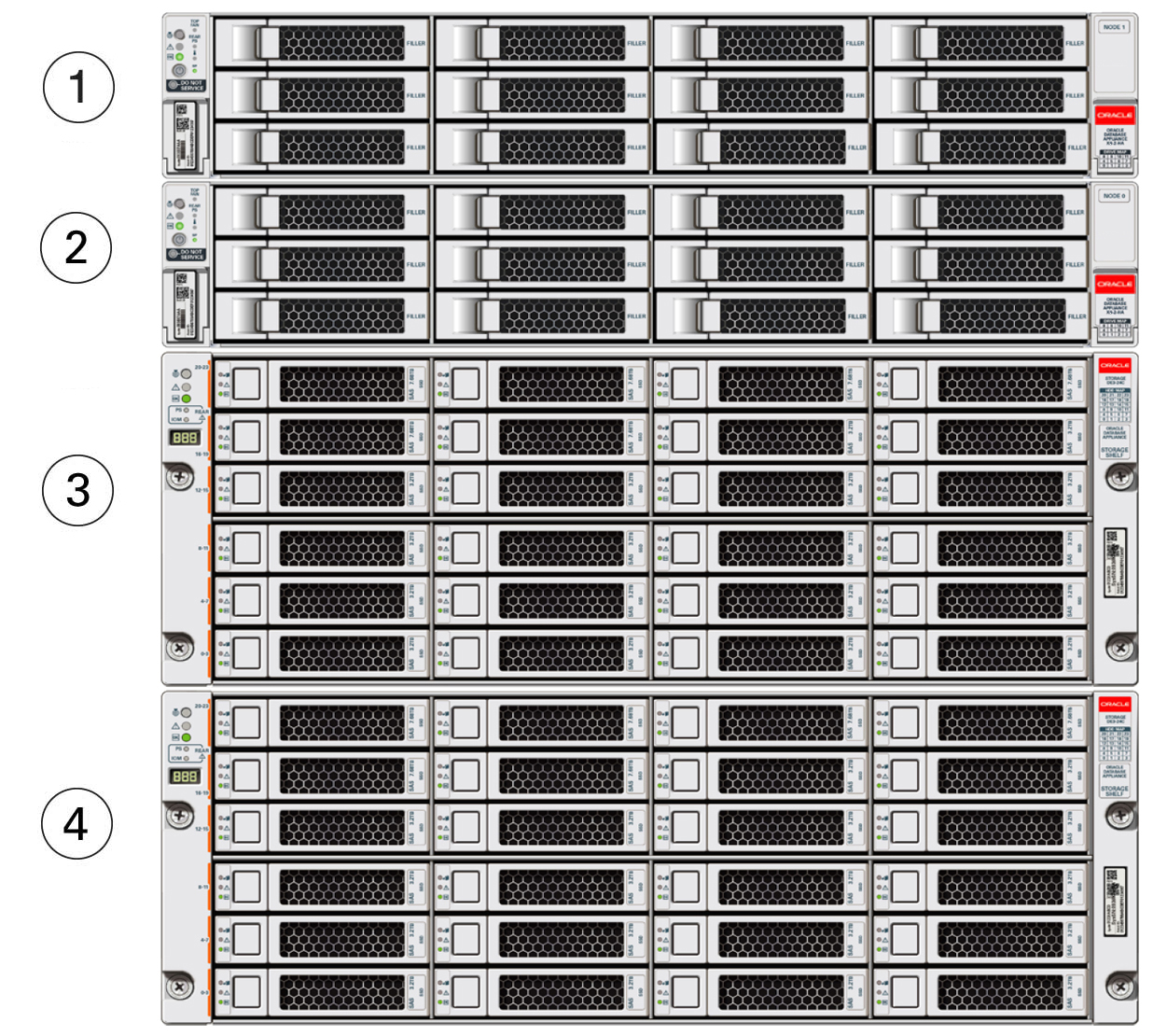
Oracle Database Appliance X9-2-HA includes two server nodes (two Oracle Server X9-2L's) and an Oracle DE3-24C storage shelf. The entire unit occupies 8RU. The optional storage expansion shelf requires an additional 4RU, increasing the total to 12RU.
The following figure shows the front of Oracle Database Appliance X9-2-HA with an optional storage expansion shelf.
| Callout | Description |
|---|---|
|
1 |
Server node 1 |
|
2 |
Server node 0 |
|
3 |
Storage shelf (DE3-24C) |
|
4 |
Optional storage expansion shelf (DE3-24C) |
- Server Node Front Panel Features
See an illustration and listing of Oracle Database Appliance X9-2-HA server node front panel features. - Storage Shelf Front Panel Features
See an illustration and listing of Oracle Database Appliance X9-2-HA storage shelf front panel features.
Parent topic: Oracle Database Appliance X9-2-HA Front and Back Panels
Server Node Front Panel Features
See an illustration and listing of Oracle Database Appliance X9-2-HA server node front panel features.
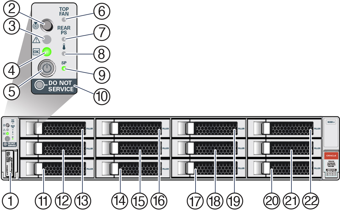
The following figure shows the components on the front panel of an Oracle Database Appliance X9-2-HA server node.
| Callout | Description |
|---|---|
|
1 |
Product Serial Number (PSN) label and Radio Frequency Identification (RFID) tag |
|
2 |
Locate LED/button: white |
|
3 |
Service Required LED: amber |
|
4 |
Power/OK LED: green |
|
5 |
Power button |
|
6 |
Fan Fault LED: amber |
|
7 |
Power Supply (PS) Fault LED: amber |
|
8 |
System Over Temperature Warning LED: amber |
|
9 |
SP OK LED: green |
|
10 |
DO NOT SERVICE |
|
11 - 22 |
Front mounted drive slots 0 - 11 (filler panels) |
Note:
When contacting Oracle Support Services, use the Top Level Identifier (TLI) instead of the serial number. You can find the TLI by looking at the top of either server node or on the top of the storage shelf. For details, see Technical Support.
Parent topic: Oracle Database Appliance X9-2-HA Front Panel
Storage Shelf Front Panel Features
See an illustration and listing of Oracle Database Appliance X9-2-HA storage shelf front panel features.
The following figure shows the Oracle Database Appliance X9-2-HA storage shelf front panel features.
Note:
There are three base configurations for the storage shelf: two fully populated and one partially populated (disk slots 6-23 are filler panels). Do not attempt to move or switch disks in the base configurations as it could cause the deployment to fail.
You have the option of upgrading the partially populated base configuration storage shelf to add disks to the empty slots. See Optional Component Installation. Upgrading the base configuration to a fully populated storage shelf will allow you to add a storage expansion shelf later, if needed.
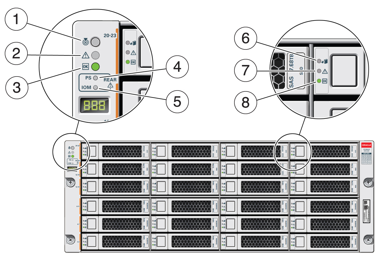
Description of the illustration gxxxx-x8-2ha_storage_shelf_front_callouts.jpg
| Callout | Description |
|---|---|
|
1 |
Storage shelf Locate indicator |
|
2 |
Storage shelf fault indicator |
|
3 |
Storage shelf OK/power indicator |
|
4 |
Storage shelf power supply fault indicator |
|
5 |
Storage shelf IO module fault indicator |
|
6 |
Drive Ready-to-Remove indicator |
|
7 |
Drive fault indicator |
|
8 |
Drive power/activity indicator |
Parent topic: Oracle Database Appliance X9-2-HA Front Panel
Oracle Database Appliance X9-2-HA Back Panel
See an illustration and listing of Oracle Database Appliance X9-2-HA back panel features.
This section describes the back panel features for Oracle Database Appliance X9-2-HA.
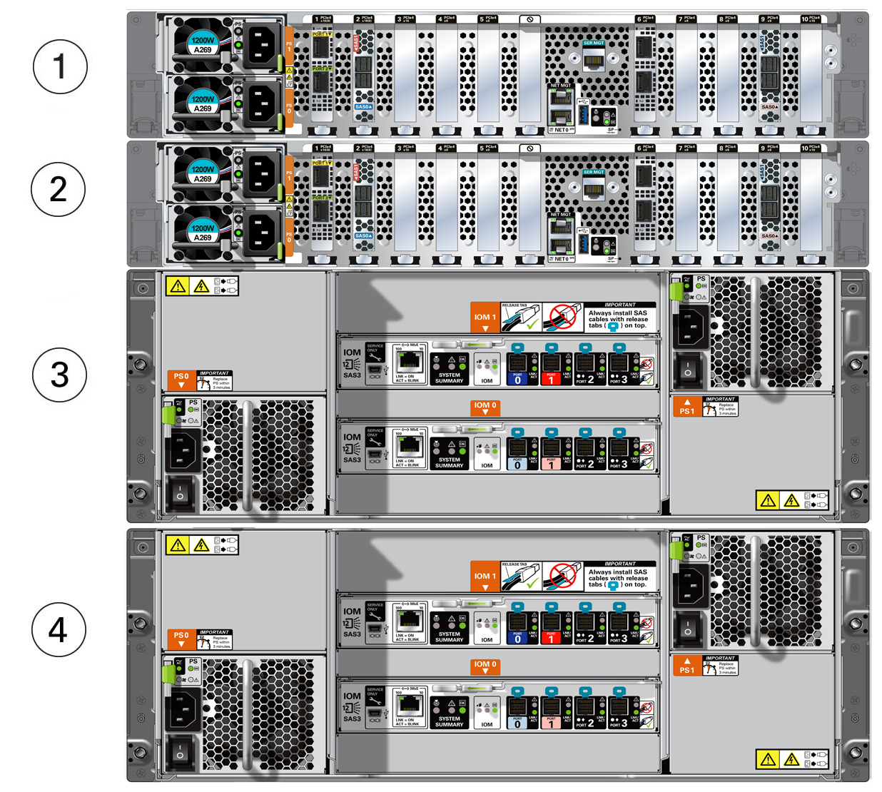
The following figure shows the Oracle Database Appliance X9-2-HA.
| Callout | Description |
|---|---|
|
1 |
Server node 1 |
|
2 |
Server node 0 |
|
3 |
Storage shelf (DE3-24C) |
|
4 |
Optional storage expansion shelf (DE3-24C) |
- Server Node Back Panel Features
See an illustration and listing of Oracle Database Appliance X9-2-HA server node back panel features. - Storage Shelf Back Panel Features
See an illustration and listing of Oracle Database Appliance X9-2-HA storage shelf back panel features.
Parent topic: Oracle Database Appliance X9-2-HA Front and Back Panels
Server Node Back Panel Features
See an illustration and listing of Oracle Database Appliance X9-2-HA server node back panel features.
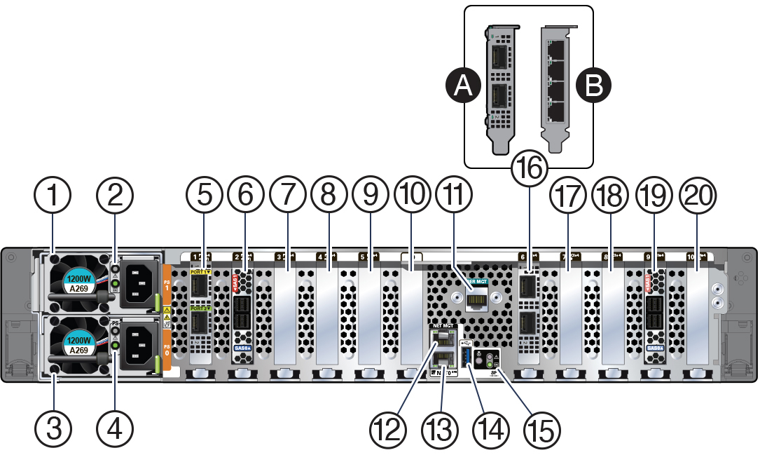
The following figure shows the components on the back panel of an Oracle Database Appliance X9-2-HA server node.
| Callout | Description |
|---|---|
|
1 |
Power Supply (PS) 1 with fan module |
|
2 |
Power Supply (PS) 1 status indicators: Service Required LED: amber, AC OK LED: green |
|
3 |
Power Supply (PS) 0 with fan module |
|
4 |
Power Supply (PS) 0 status indicators: Service Required LED: amber, AC OK LED: green |
|
5 |
PCIe card slot 1: Oracle Dual Port 25Gb Ethernet Adapter provides two ports with SFP28 connections for a private cluster interconnect between server nodes |
|
6 |
PCIe card slot 2: provides two SAS3 connectors used to connect the servers to the storage shelf and the storage expansion shelf |
|
7 |
PCIe card slots 3: filler panel |
|
8 |
PCIe card slot 4: filler panel, or optional Oracle Dual Port 25Gb Ethernet Adapter, or optional Oracle Quad Port 10GBase-T Adapter |
|
9 |
PCIe card slots 5: filler panel |
|
10 |
Not used |
|
11 |
SER MGT port: RJ-45 serial port used to connect to the Oracle ILOM service processor |
|
12 |
NET MGT port: 10/100/1000Base-T network interface port with RJ-45 connector used to connect to the Oracle ILOM service processor |
|
13 |
100/1000BASE-T network interface port with RJ-45 connector: NET 0 |
|
14 |
USB 3.0 connector |
|
15 |
System status indicators: Locate LED: white, Service Required LED: amber, Power/OK LED: green |
|
16 |
PCIe card slot 6: public network interface card
|
|
17 |
PCIe card slot 7: filler panel |
|
18 |
PCIe card slot 8: filler panel, or optional Oracle Dual Port 25Gb Ethernet Adapter, or optional Oracle Quad Port 10GBase-T Adapter |
|
19 |
PCIe card slot 9: provides two SAS3 connectors used to connect the servers to the storage shelf and the storage expansion shelf |
|
20 |
PCIe card slot 10: filler panel |
Parent topic: Oracle Database Appliance X9-2-HA Back Panel
Storage Shelf Back Panel Features
See an illustration and listing of Oracle Database Appliance X9-2-HA storage shelf back panel features.
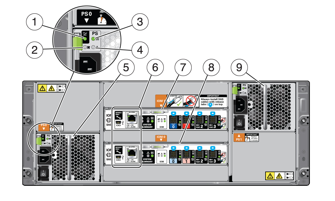
The following figure shows the Oracle Database Appliance X9-2-HA storage shelf back features.
Note:
The network ports on the storage shelf are intended for use by service engineers only.
| Callout | Description |
|---|---|
|
1 |
AC power indicator |
|
2 |
Fan fail indicator |
|
3 |
Power supply status indicator |
|
4 |
DC power fail indicator |
|
5 |
Power Supply with fan module 0 |
|
6 |
Service ports (reserved for Oracle Service only) |
|
7 |
SAS I/O module 1 |
|
8 |
SAS I/O module 0 |
|
9 |
Power Supply with fan module 1 |
Parent topic: Oracle Database Appliance X9-2-HA Back Panel
Oracle Database Appliance Specifications
This section describes the physical, electrical and environmental specifications for the various Oracle Database Appliance models.
- Physical Specifications for Oracle Database Appliance X9-2 Series
- Electrical Specifications for Oracle Database Appliance X9-2 Series
- Environmental Specifications for Oracle Database Appliance X9-2 Series
Parent topic: Overview of Oracle Database Appliance
Physical Specifications for Oracle Database Appliance X9-2 Series
| Item | Oracle Database Appliance X9-2S | Oracle Database Appliance X9-2L | Oracle Database Appliance X9-2-HA |
|---|---|---|---|
|
Height |
86.9 mm (3.4 in) |
86.9 mm (3.4 in) |
86.9 mm (3.4 in) per server node 175 mm (6.9 in) per storage shelf |
|
Width |
445 mm (17.5 in) |
445 mm (17.5 in) |
445 mm (17.5) per server node 483 mm (19 in) per storage shelf |
|
Depth |
759.4 mm (29.9 in) |
759.4 mm (29.9 in) |
759.4 mm (29.9 in) per server node 630 mm (24.8 in) per storage shelf |
|
Weight |
28.6 kg (63 lbs) |
28.6 kg (63 lbs) |
28.6 kg (63 lbs) per server node 38.0 kg (84 lbs) per storage shelf |
Parent topic: Oracle Database Appliance Specifications
Electrical Specifications for Oracle Database Appliance X9-2 Series
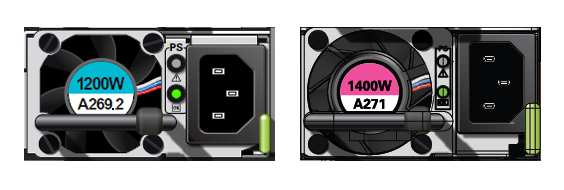
There are two types of power supplies supported by the server: the A269.2 or A271/A271A. Each power supply has a label that tells which one has been installed (as shown in the illustration below). Both types are described in the table that follows.
Note:
The A271 and A271A power supplies are functionally identical. Either are supported in the system.| Item | Oracle Database Appliance X9-2S | Oracle Database Appliance X9-2L | Oracle Database Appliance X9-2-HA |
|---|---|---|---|
|
Server node power supply output rated maximum |
For systems with A269.2 power supplies: 1200W at 100-127 VAC or 1200W at 200-240 VAC For systems with A271/A271A power supplies: 1400W at 200-240 VAC |
For systems with A269.2 power supplies: 1200W at 100-127 VAC or 1200W at 200-240 VAC For systems with A271/A271A power supplies: 1400W at 200-240 VAC |
For server nodes with A269.2 power supplies: 1200W at 100-127 VAC or 1200W at 200-240 VAC For server nodes with A271/A271A power supplies: 1400W at 200-240 VAC |
|
Server node AC power |
For systems with A269.2 power supplies: 10A at 100-127 VAC or 7A at 200-240 VAC For systems with A271 power supplies: 10A at 200-240 VAC |
For systems with A269.2 power supplies: 10A at 100-127 VAC or 7A at 200-240 VAC For systems with A271 power supplies: 10A at 200-240 VAC |
For server nodes with A269.2 power supplies: 10A at 100-127 VAC or 7A at 200-240 VAC For server nodes with A271 power supplies: 10A at 200-240 VAC |
|
Storage shelf power supply output rated maximum |
Not included |
Not included |
580W at 100-127 VAC 580W at 200-240 VAC |
|
Storage shelf AC Power |
Not included |
Not included |
8A at 100-127 VAC 3A at 220-240 VAC |
|
Power usage |
For more information on power consumption, see Oracle Server X9-2L Power Calculator. |
For more information on power consumption, see Oracle Server X9-2L Power Calculator. |
Two server nodes
Storage shelf (24 SSDs)
Storage shelf (6 SSDs, 18 HDDs)
|
Parent topic: Oracle Database Appliance Specifications
Environmental Specifications for Oracle Database Appliance X9-2 Series
| Item | Oracle Database Appliance X9-2S | Oracle Database Appliance X9-2L | Oracle Database Appliance X9-2-HA |
|---|---|---|---|
|
Operating temperature |
5° C to 35° C (41° F to 95° F) |
5° C to 35° C (41° F to 95° F) |
5° C to 35° C (41° F to 95° F) |
|
Nonoperating temperature |
-40° C to 70° C (-40° F to 158° F) |
-40° C to 70° C (-40° F to 158° F) |
-40° C to 70° C (-40° F to 158° F) |
|
Operating humidity |
10% to 90% relative humidity, noncondensing |
10% to 90% relative humidity, noncondensing |
10% to 90% relative humidity, noncondensing |
|
Nonoperating humidity |
Up to 93% relative humidity, noncondensing |
Up to 93% relative humidity, non-condensing |
Up to 93% relative humidity, non-condensing |
|
Operating altitude |
Up to 3,000 m* (9,840 ft); maximum ambient temperature is derated by 1° C per 300 m above 900 m * Except in China markets where regulations might limit installations to a maximum altitude of 2,000 m (6,560 ft) |
Up to 3,000 m* (9,840 ft); maximum ambient temperature is derated by 1° C per 300 m above 900 m * Except in China where regulations might limit installations to a maximum altitude of 2,000 m (6,560 ft) |
Up to 3,000 m* (9,840 ft); maximum ambient temperature is derated by 1° C per 300 m above 900 m * Except in China where regulations might limit installations to a maximum altitude of 2,000 m (6,560 ft) |
|
Nonoperating altitude |
Up to 12,000 m (39,370 ft) |
Up to 12,000 m (39,370 ft) |
Up to 12,000 m (39,370 ft) |
|
Cooling |
For more information on power consumption, see Oracle Server X9-2L Power Calculator |
For more information on power consumption, see Oracle Server X9-2L Power Calculator |
Server node, see Oracle Server X9-2L Power Calculator Storage shelf
|
|
Acoustic noise |
7.1 Bels A-weighted operating, 7.0 Bels A-weighted idling |
7.1 Bels A-weighted operating, 7.0 Bels A-weighted idling |
8.1 Bels A-weighted operating, 5.8 Bels A-weighted idling |
Parent topic: Oracle Database Appliance Specifications
Technical Support
How to obtain technical support for your appliance.
For technical support, go to:
https://support.oracle.com/portal/
| Oracle Database Appliance X9-2S/X9-2L | Oracle Database Appliance X9-2-HA |
|---|---|
|
Report the serial number located on the front panel of the system, the top of the system, or on the Customer Information Sheet that is shipped with the system. You only need to extend the server node a couple of inches on its slide rails to see the serial label on the top of the system. You do not need to release any cables, or slide it to the extended maintenance position. |
Report the Top Level Identifier (TLI). To see the TLI, look on the Customer Information Sheet or look at the top of a server node or storage shelf on the left-hand side towards the front. The TLI part number and TLI serial number are the same for the factory-bundled server nodes of an appliance. The following figure shows an example Top Level Identifier label: If the appliance is in a rack where you cannot see the TLI, do one of the following:
|
Parent topic: Overview of Oracle Database Appliance
