Sun Ethernet Fabric Operating System PVRST+ Administration Guide

Exit Print View

Updated: July 2015


Topology Example

This topology is referenced in the descriptions and instructions in this guide.
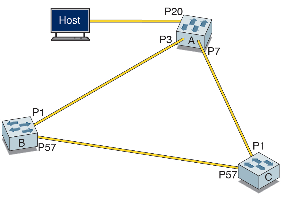
image:Figure showing a sample topology

In this configuration, each switch A, B, and C, has two interfaces connected to the other two switches. Switch A has a third interface port 20 (P20) connected to a host. In addition to the default VLAN 1, VLAN 10 and VLAN 20 are used as command examples. The topology includes these details:

Switch
MAC Address
VLAN 10 Address and Mask
A (hostname - NEM-1)
00:14:4f:6c:56:6f
192.168.10.199/255.255.255.0
B (hostname - TOR-1)
00:14:4f:6c:69:ed
192.168.10.144/255.255.255.0
C (hostname - SEFOS-2)
00:14:4f:6c:6e:0d
192.168.10.149/255.255.255.0