| Skip Navigation Links | |
| Exit Print View | |

|
Sun Server X4-2 HTML Documentation Collection |
Getting the Latest Software and Firmware
About the Installation Procedure
Installation Procedure Overview
Preparing for Server Installation
Server Physical Specifications
Tools and Equipment Needed for Installation
Optional Component Installation
About Server Features and Components
Front Panel Status Indicators, Connectors, and Drives
Back Panel Status Indicators, Connectors, and PCIe Slots
Server Management Software Overview
Getting Server Firmware and Software Updates
Firmware and Software Access Options
Getting Firmware and Software From MOS or PMR
Installing Updates Using Other Methods
Installing the Server Into a Rack
Safety Precautions When Rackmounting the Server
Stabilize the Rack for Installation
Attach Tool-less Slide-Rail Assemblies
Install the Server Into the Slide-Rail Assemblies
Install the Second-Generation Cable Management Arm
Remove the Second-Generation Cable Management Arm
Install the First-Generation Cable Management Arm
Verify Operation of Slide-Rails and CMA
Rear Cable Connections and Ports
Attaching Data Cables to the Server
Connecting Power Cords to the Server
Oracle ILOM Hardware and Interfaces
Logging In to Oracle ILOM Using a Local Serial Connection
Logging In to Oracle ILOM Using a Remote Ethernet Connection
Accessing the Host Console Through Oracle ILOM
Troubleshooting the Service Processor Connection
Setting Up Software and Firmware Using Oracle System Assistant
Accessing Oracle System Assistant
Setting Up Software and Firmware Using Oracle System Assistant
Setting Up an Operating System and Drivers
Configuring Server Drives for OS Installation
RAID Configuration Requirements
Configuring Storage Drives Into RAID Volumes Using Oracle System Assistant
Configuring RAID Using the BIOS RAID Configuration Utilities
Configuring the Preinstalled Oracle Solaris 11.1 Operating System
Preinstalled Oracle Solaris 11.1 Image BIOS Boot Mode Restriction
Preinstalled Operating System RAID Limitations
Oracle Solaris 11.1 Configuration Worksheet
Configure the Preinstalled Oracle Solaris 11.1 Operating System
Oracle Solaris 11.1 Operating System Documentation
Configuring the Preinstalled Oracle Linux 6.x Operating System
Preinstalled Oracle Linux Image BIOS Boot Mode Restriction
Oracle Linux 6.x Configuration Worksheet
Configure the Preinstalled Oracle Linux 6.x Operating System
Registering Oracle Linux and Activating Automatic Update
Oracle Linux 6.x Operating System Documentation
Configuring the Preinstalled Oracle VM 3.2 Software
Preinstalled Oracle VM Image BIOS Boot Mode Restriction
Preinstalled Oracle VM Server and Oracle VM Manager Compatibility Requirements
Oracle VM Server Configuration Worksheet
Configure the Preinstalled Oracle VM Server
Powering Off the Server for Orderly Shutdown
Powering Off the Server for Immediate Shutdown
Troubleshooting Installation Issues
Technical Support Information Worksheet
Locating the System Serial Number
About Oracle Solaris Operating System Installs
Oracle Solaris OS Installation Task Map
Selecting the Console Display Option
Selecting the Boot Media Option
Selecting the Installation Target Option
Oracle Solaris OS Installation Options
Oracle System Assistant Overview
Preparing to Install the Operating System
Installing the Oracle Solaris Operating System
Installing Oracle Solaris on a Single System Using Oracle System Assistant
Installing the Oracle Solaris 10 or 11 Operating System on a Single System Using Media
Oracle VM Installation Task Map
Selecting the Console Display Option
Selecting the Boot Media Option
Selecting the Installation Target Option
Oracle VM Installation Options
Oracle System Assistant Overview
Preparing to Install Oracle VM
Verify the BIOS Factory Defaults
Disable VT-d and SR-IOV in BIOS
Installing Oracle VM on a Single System Using Oracle System Assistant
Installing Oracle VM on a Single System Using Media
Post Installation Tasks for Oracle VM
Configuring Network Interfaces
About Linux Operating System Installs
Supported Linux Operating Systems
Oracle Unbreakable Enterprise Kernel for Linux
Selecting the Console Display Option
Selecting the Boot Media Option
Selecting the Installation Target Option
Oracle System Assistant Overview
Preparing to Install the Operating System
Installing a Linux Operating System
Installing a Linux OS on a Single System Using Oracle System Assistant
Installing Oracle Linux on a Single System Using Media
Installing Red Hat Enterprise Linux on a Single System Using Media
Installing SUSE Linux Enterprise Server on a Single System Using Media
Configuring Network Interfaces
About Microsoft Windows Server Operating System Installs
Windows OS Installation Task Map
Supported Windows Operating Systems
SAS PCIe HBAs Requiring LSI Mass Storage Driver for Windows Server 2008 SP2
Selecting the Console Display Option
Selecting the Boot Media Option
Selecting the Installation Target Option
Windows OS Installation Options
Oracle System Assistant Overview
Preparing to Install the Operating System
Installing a Windows Server Operating System
Installing Windows Server on a Single System Using Oracle System Assistant
Installing Windows Server on a Single System Using Media
Post Installation Tasks for Windows Server
Supplemental Software Component Options
Installing Device Drivers and Supplemental Software
VMware ESXi Installation Task Map
Supported VMware ESXi Software
Selecting the Console Display Option
Selecting the Boot Media Option
Selecting the Installation Target Option
VMware ESXi Installation Options
Preparing to Install VMware ESXi
Configuring the VMware ESXi 5.0 Software or the Server Hardware to Support Network Connections
Installing VMware ESXi on a Single System Using Media
Post Installation Tasks for VMware ESXi
Configure Network Adapter Settings
Determine the MAC Address of a Connected Server Network Port
Update the VMware ESXi Software
Configuring Network Interfaces
About Server and Component Status Indicators
Service Troubleshooting Task List
Locate the Server Serial Number
Electrostatic Discharge Safety
Preparing the Server for Component Replacement
Servicing CRUs That Do Not Require Server Power-Off
Servicing Storage Drives (CRU)
Servicing Power Supplies (CRU)
Servicing CRUs That Require Server Power-Off
Servicing the Internal USB Flash Drives (CRU)
Servicing the Disk Backplane (FRU)
Servicing the Front Indicator Module (FRU)
Remove the Front Indicator Module
Install the Front Indicator Module
Servicing the Motherboard (FRU)
Servicing the SAS Cables (FRUs)
Remove Storage Drive SAS Cables
Install Storage Drive SAS Cables
Returning the Server to Operation
Removing and Installing Server Filler Panels
Reinstall the Server Chassis Into the Rack
Return the Server to the Normal Rack Position
Reconnect Data Cables and Power Cords
Setting Up BIOS Configuration Parameters
Managing the BIOS Configuration
Accessing the BIOS Setup Utility
Using BIOS for Resource Allocation
Common BIOS Setup Utility Tasks
BIOS Setup Utility Menu Options
UEFI Driver Control Menu Selections
BIOS Save & Exit Menu Selections
Monitoring Components and Identifying SNMP Messages
Monitoring Component Health and Faults Using Oracle ILOM
 | Caution - The correct processor removal/replacement tool must be used to remove and replace a processor; otherwise, the processor or the processor socket might be damaged. |
Selecting the correct processor removal/replacement tool is a two-step process. First you determine the size of the processor that is being replaced, then you select the removal/replacement tool that fits that size.
The processors supported by the Sun Server X4-2 come in two sizes. The processors with 10 or fewer cores are smaller than the processors with 12 cores. You can determined the size of the processor that you are going to remove and replace in either of two ways:
Use Oracle Integrated Lights Out Manager (ILOM) to display processor information.
For instructions for using Oracle ILOM to display processor information, see the Oracle Integrated Lights Out Manager (ILOM) 3.1 Documentation Library.
Or
Visually check the size of the processor installed in the server.
This requires that you remove the processor heatsink and open the processor independent loading mechanism (ILM) assembly that holds the processor in the socket. For instructions, see Remove a Processor. This is the same procedure that you will use when you remove the processor.
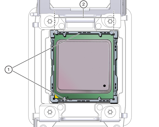
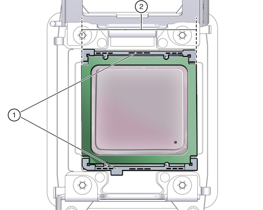
If you choose to visually check the size of the processor, refer to the next two figures to see how to distinguish the smaller processors from the larger processors. Smaller Processor Installed in a Motherboard Processor Socket shows a smaller processor installed. Notice that the right and left edges of the processor are within the boundaries of the processor alignment brackets.
Figure 58 Smaller Processor Installed in a Motherboard Processor Socket

Figure Legend
1 Processor alignment brackets
2 Processor left and right edges are within alignment bracket boundaries
Larger Processor Installed in a Motherboard Processor Socket shows a larger processor installed. Notice that the right and left edges of the processor extend beyond the boundaries of the processor alignment brackets.
Figure 59 Larger Processor Installed in a Motherboard Processor Socket

Figure Legend
1 Processor alignment brackets
2 Processor left and right edges extend beyond alignment bracket boundaries
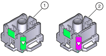
After you have determined the size of the processor installed in your server, select the correct processor removal/replacement tool. Like the processors, the processor removal/replacement tool also comes in two sizes. The tool for the smaller processors (processors with 10 or fewer cores) is color-coded green. The tool for the larger processors (12-core processors) is color-coded pink. See Color-Coded Processor Removal/Replacement Tools.
Figure 60 Color-Coded Processor Removal/Replacement Tools

Figure Legend
1 Green, color-coded removal/replacement tool for the smaller processors—models E5-2609 V2 (4-core), E5-2630 V2 (6-core), E5-2650 V2 (8-core), and E5-2690 V2 (10-core)
2 Pink, color-coded removal/replacement tool for the larger processor—model E5-2697 V2 (12-core)
 | Caution - The pink color-coded processor removal/replacement tool must be used only with the larger processor (the 12-core processor). Likewise, the green color-coded removal/replacement tool must be used only with smaller processors (the 4-, 6-, 8-, and 10-core processors); otherwise, the processor or the processor socket might be damaged. |
The following table provides an easy reference for matching a processor (by number of cores or model number) to the correct processor removal/replacement tool.
Table 36 Processor Model Numbers by Number of Cores
|
Note - The correct processor removal/replacement tool is included in the box with the replacement processor. Additionally, both removal/replacement tools ship with replacement motherboards.