JavaScript is required to for searching.
Skip Navigation Links
Exit Print View
Sun Blade 6000 Modular System

Service Manual

search filter icon
search icon

Document Information

Using This Documentation

Downloading Chassis Firmware

Documentation and Feedback

About This Documentation

Service Manual Overview

Service Procedures Overview

Server Components Overview

Modular System Components

Internal System Components

Monitoring Faults

About Fault Management

External and Internal Faults

Oracle ILOM Fault Management

Monitoring Faults Using Fault LEDs

Chassis and CMM LEDs

Power Supply LEDs

Rear Fan LEDs

Monitoring Faults Using Oracle ILOM

Viewing System Component Status

Monitor Faults With the Oracle ILOM CLI Event Log

Preparing for Service

Identifying Component Types and Service Classifications

Identifying Chassis Models and Replacement Components

Chassis Part Numbers

Identifying the Chassis Model Using the Midplane Part Number

Identifying Chassis Replacement Components

Identifying the CMM Using the CMM Product Part Number

Gather Required Tools

Prevent ESD Damage

Powering Off the System and Components

Power Off the Server Modules and Storage Modules

Power Off the Chassis

Removing the Chassis From the Rack

Prepare the Chassis for Removal

Depopulate the Chassis

Remove the Chassis From the Rack

Replacing Customer-Replaceable Units

Replacing a Power Supply

Remove a Power Supply

Install a Power Supply

Replacing a Front Fan Tray

Remove a Front Fan Tray

Install a Front Fan Tray

Replacing a Server or Storage Module

Remove a Server or Storage Module

Install a Server or Storage Module

Replacing the FIM

Remove a FIM

Install a FIM

Replacing a PCIe EM

PCIe EM Service Overview

Remove a PCIe EM

Install a PCIe EM

Replacing a NEM

Remove a NEM

Install a NEM

Replacing a Rear Fan Module

Remove a Rear Fan Module

Install a Rear Fan Module

Replacing the Fan Board

Remove the Fan Board

Install the Fan Board

Replacing the CMM

Remove the CMM

Install the CMM

CMM Reset Sequence

Replacing Field-Replaceable Units

Replacing the Midplane

Remove the Midplane

Install the Midplane

Replacing an Internal Power Cable

Remove an Internal Power Cable

Install an Internal Power Cable

Returning the Modular System to Operation

Reinstalling the Chassis Into a Rack

Lift and Install the Chassis

Repopulate the Chassis

Reinstall Cables on the Components

Applying Power to the Chassis

Power-On Sequence

Apply Power to the Modular System

Update FRU Information After Replacing the Midplane

Verify Modular System Functionality

Glossary

Index

Lift and Install the Chassis

Perform the following steps using a mechanical lift, or manually with four people. If you are manually installing the chassis, ensure that you depopulate the chassis first. See Depopulate the Chassis.


Caution

Caution - The chassis is heavy. Use a mechanical lift or depopulate the chassis and use four people to lift the chassis.


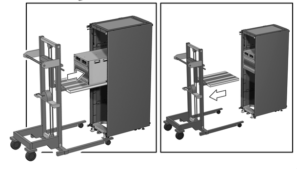
  1. Raise the chassis so that the bottom of the chassis is at the height of the rail shelf.
  2. Slide the chassis into the rack until the chassis front mounting flanges contact the rack posts.
    image:Figure showing the chassis sliding in from a mechanical lift.
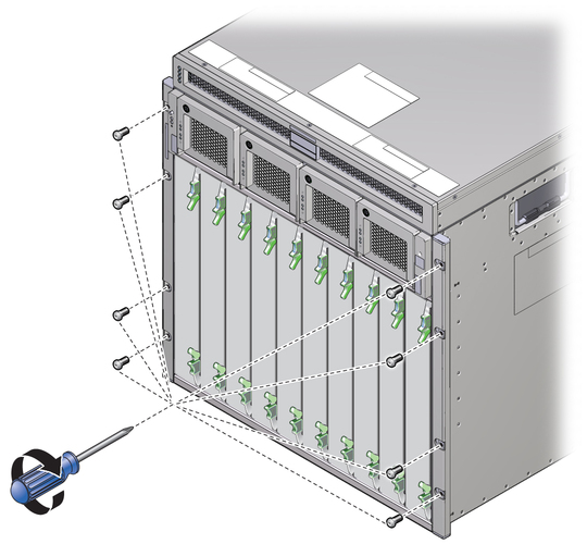
  3. Install eight screws to secure the front of the chassis to the rack.
    image:Figure showing the location of the 8 front rackmounting screws.
  4. Fasten two upper rear brackets to the rack.

    Place the screws in the two outside holes of the bracket, and leave the middle hole empty.


    Note - Permanent installation of these two brackets is required for seismic bracing.
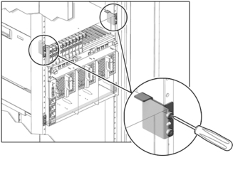


    image:Figure showing screws securing the upper rear brackets.
  5. If you depopulated the chassis, repopulate the chassis.

    See Repopulate the Chassis.

Related Information