


|
The following sections describe how to configure and use edgeflows:
The ALE engine of WebLogic RFID Edge Server collects and filters data from RFID-labeled items moving through the supply chain. This process involves no business logic. However, data gathered during this process can be sent through local edge flows on the Edge Server, which apply business logic to the RFID data at the edge. Data that results from this workflow processing may be sent to the organization's enterprise data center or other destinations.
You construct edge flows to satisfy use cases. The edge flows are constructed from Edgeflow modules, which take input messages (event or programming cycle reports, or output from other modules), and emit edge flow messages according to embedded business logic.
Edge flows can be viewed as a series of actions triggered by a related event. For example, the observation of an EPC on an RFID-tagged case of consumer goods travelling down a conveyor belt could increment an LED counter, change a stack light to green, send an EPCIS event, or send a notification to another system.
Figure 2-1 shows edge flows in the context of EPC data.

Every edgeflow module has configuration parameters that determine the exact behavior of each module instance. For example, the External Sender module has parameters that let the user specify an XSLT file, destination URI(s), input data connections, and error output connections for a given instance of that module, as shown in Figure 2-2.
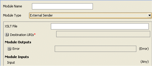
An edgeflow module instance can receive data from, and send data to, other module instances. It sends data to other module instances through output ports and receives data from other module instances through input ports.
A module can have multiple input ports and multiple output ports. The different ports are typically based on the different functions of the ports. For example, the Tag Accumulator module adds the tags it receives on its Add port to its internally-accumulated list and deletes the tags it receives on its Delete port from its internal list. Similarly, it sends the running list of tags on the Running Tag List output port and the final list of tags on the Final Tag List output port.
The input and output ports of edgeflow modules are typed, which means that they accept or send only specific data types defined by the port. For example, the Tag List Filter module accepts only ECReports in its input port and sends only Tag Lists through its tag list output port.
The structure of the edgeflow modules is illustrated in Figure 2-3.
Each module can contain the following:
The number of input and output ports is based on the function of the module. All ports are typed.
The WebLogic RFID Edge Server provides the edgeflow modules shown inTable 2-1.
Prior to the version 3.0 release of the Edge Server, workflow modules were large single-focused components that addressed specific use cases. These modules included a Bidirectional Portal Module, an Observe Portal Module, and Numeric Display Module, Stack Light Module and Message Notifier Module helper modules
Starting with version 3.0 of the Edge Server, limited support is provided for the legacy modules. New legacy module instances cannot be created using the Admin Console and messaging between the legacy modules and the new edgeflow modules is not supported. For more information about the legacy modules, see Workflow Module Reference for Versions Prior to 3.0 .
The legacy modules are replaced by a number of small, reusable edgeflow modules that provide finer granularity functions and can be used as building blocks to satisfy use cases. The building blocks can be used to create simple or complex edgeflows and provide a flexibility that minimizes the need to write custom modules.
Before you configure an edgeflow, you may need to configure the ECSpec whose reports will provide input to the edgeflow. See Using the RFID Edge Server Administration Console for instructions on configuring an ECSpec.
You must also have a working installation of the WebLogic RFID Edge Server, including one or more hardware devices (stack lights, RFID devices, and LED displays).
If your edgeflow sends EPCIS events to the RFID Enterprise Server, you will also need a working installation of the WebLogic RFID Enterprise Server.
You configure edgeflows by configuring edgeflow modules and connecting them together, using the RFID Edge Server Administration Console. Edgeflow modules are connected to one another by referring to the name of the module and the name of the input port that is receiving output from another module.
Consider the example shown in Figure 2-4. The B to A Tag List output of this Directional Filter (Auto Configuration) module is sent to the Tag List input port of the interior-door-observeB2A EPCIS Object Event Generator module.
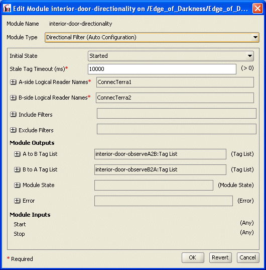
These drivers are defined in the RFID_EDGE_HOME/etc/edge.props file, where RFID_EDGE_HOME is the directory where you installed the RFID Edge Server software.
For testing purposes, as an RFID device, you can configure the Reader Simulator software included with the RFID Edge Server.
For more information on RFID device configuration, see the RFID Reader Reference and any manufacturer documentation provided with your hardware.
For more information on creating ECSpecs, see Using the RFID Edge Server Administration Console.
Active subscriptions allow you to test that the edgeflow is functioning correctly, and that the Edge Server is sending messages to the configured locations and devices.
You should see evidence of edgeflow activity (Edgeflow messages arriving at notification destinations and delivery of ECReports).
The RFID Edge Server 3.0 software provides a number of sample edgeflows, available in the RFID_EDGE_HOME/samples/EdgeFlows directory. Each of the edgeflow samples can be imported into a RFID Edge Server 3.0 system and modified to meet specific customer needs.
Use the following steps to import the sample edgeflows:
This imports the ECSspec (if applicable), the edgeflow modules, and starts the edgeflow. You can view or modify the module configurations through the Administration Console.
The following sections describe the sample edgeflows. You can load each of the edgeflow samples and use the Administration Console to view the configuration properties of each module.
| Note: | The first example, Example: Simple Observe Edgeflow, uses screen shots to provide some context about how edgeflow modules connect via the user interface. Having established this context, subsequent examples do not require or include the screen shots. |
This example (shipping-receiving-door.xml) creates an edgeflow that reads tags, creates an OBSERVE Object Event for each tag, and sends the event to the Edge Server console. This example represents a shipping or receiving door that reads all tags and reports OBSERVE events for the tags that pass through.
The example uses the reader simulator and reports events to the Edge Server console. In a production environment, the reader simulator would be replaced by a real reader and the events would be reported to an external system using JMS or HTTP.
A diagram of this edgeflow is shown in Figure 2-5.

The following sequence summarizes the functions of each component of this edgeflow:
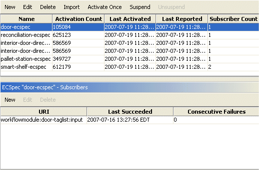
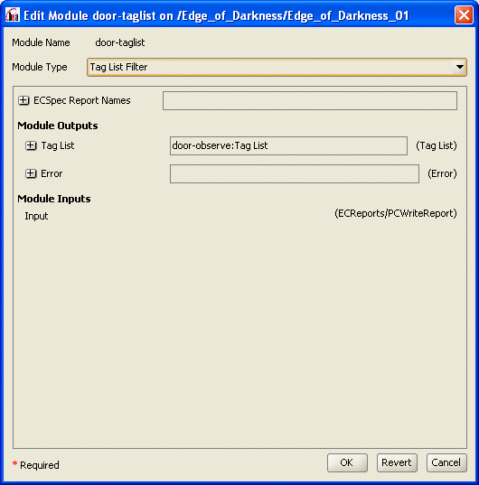
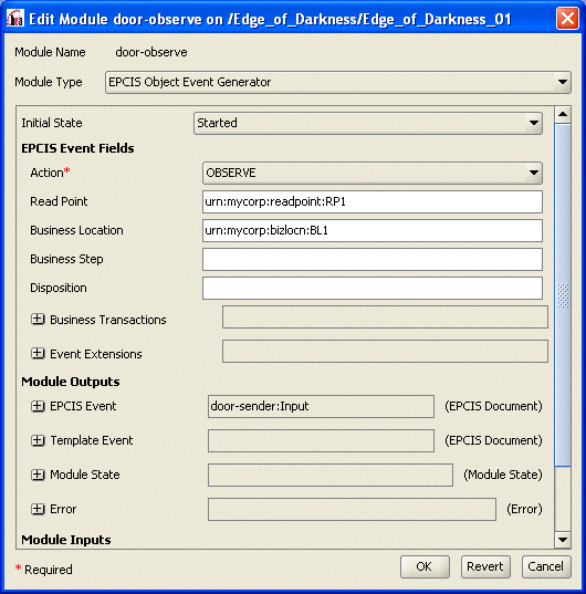
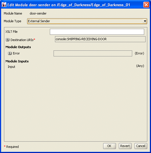
The destination URI for the External Sender module is defined as: console:SHIPPING-RECEIVING-DOOR.
You could instead configure this destination URI to use HTTP to send the events, using the following format: http://<host>:<port>/module/<modulename>:<portname>.
This sample (pallet-building-station) demonstrates a pallet building use case. In the example, the EPCs that are read during the process are accumulated to create and EPCIS Aggregation event for the pallet.
The aggregation event is created when no tags are detected for 10 seconds (the Tag Accumulator module is configured to accumulate for 10 seconds).
The aggregation event is then sent to a specified destination. In this example, the event is sent to the Edge Server console. Any errors that occur during this process are also sent to the Edge Server console.
A diagram of this example is shown in Figure 2-10.

The following sequence summarizes the function of each component of the Pallet Building station example:
After the 10 seconds have passed, the Final Tag List is sent to an EPCIS Aggregation Event Generator module Tag List input.
An aggregation ADD event is generated from the Tag List input and sent to an External Sender module. If an error occurs during this process, an error message is sent to an additional External Sender module.
This sample (store-interior-door.xml) demonstrates a use case where tags, and the direction they are moving while passing through a door, are detected. For the detected tags, an EPCIS event is generated, and includes the detected direction of a tag while passing through a doorway. The EPCIS event is sent to external destinations.
Figure 2-11 shows a diagram of this example.
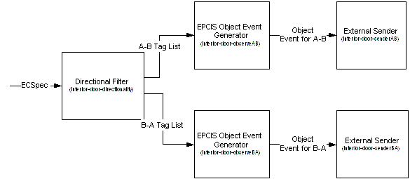
The following sequence summarizes the function of each component of the Directionality edgeflow:
Instead, the Directional Filter (Auto Configuration) module (interior-door-directionality) creates an ECSpec for the read points (configured via the A-side and B-side logical reader names) and subscribes itself to receive notifications of EPC sightings. Logical reader names are required to be configured for each point .
Specifically, it configures two ECSpecs (interior-door-directionality-DirectionalityPointA and interior-door-DirectionalityPointB) that read from antenna 1 (ConnecTerra1) and antenna 2 (ConnecTerra) of the reader simulator, respectively.
Consider the antenna locations to be the two sides of the door.
The tag lists are sent to two EPCIS Object Event Generator modules: interior-door-observeA2B:Tag List and interior-door-observeB2A:Tag List
This example (pallet-reconcilliation.xml) demonstrates a pallet reconciliation use case that includes sending HTTP messages between edgeflow modules and external systems.
There are two components of this example: the edge server edgeflow component that you import via pallet-reconcilliation.xml, and a target Web container component that generates and returns a manifest.
For the Web container component, the example includes Java code, XML files, and .JSP files to create a manifest in response to a request. The example is already built, but includes a build file in case you want to make changes and rebuild.
| Note: | Your modules would typically request the manifest from an external system. However, to keep the example simple it assumes that the supplied web client on localhost is used to get the manifest. |
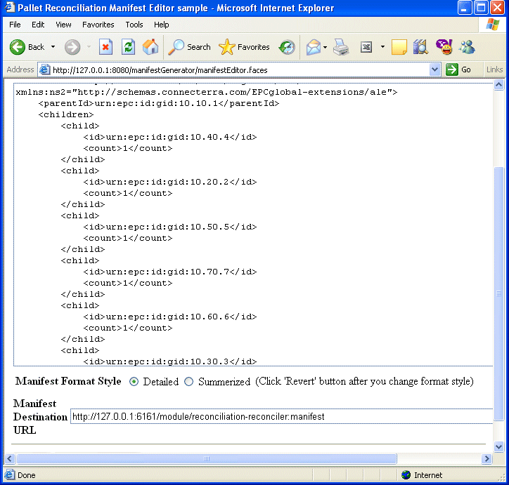
The directions for running this portion of the example are provided in Configuring the External System to Generate the Manifest.
Figure 2-12 provides a diagram of this example.
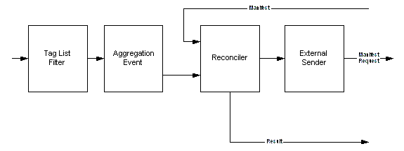
The following sequence summarizes the function of each component of the Pallet Reconciliation example:
The acceptable match is 100 percent and extra children are allowed.
The Aggregation Reconciler module uses five external sender modules to send the results of the reconciliation to different ports on the Administration Server Console:
reconciliation-result-parentMatched-sender:Input sends the result of reconciliation (boolean indicating success or failure).
reconciliation-result-childrenMatched-sender:Input sends the result of reconciliation (boolean indicating success or failure).
reconciliation-result-missing-sender:Input sends a manifest identifying any missing entries.
reconciliation-result-extra-sender:Input sends a manifest identifying extra entries.
reconciliation-result-error-sender:Input sends an error report.
The External Sender also sends console notification so that the Edge Server console displays the aggregation event sent.
The Web container portion of this example is already built and you do not generally need to rebuild it. However, if you make changes and need to rebuild, the build file is located in samples\EdgeFlows\PalletReconciliation\manifestGenerator\build.bat .
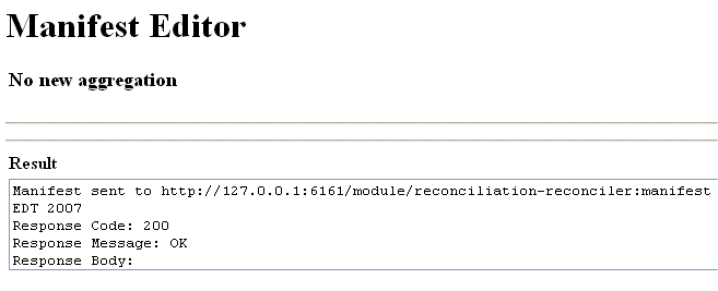
Use the following steps to run this example:
If the context path for the application is not http://localhost:8080/manifestGenerator, then you must change the destination URIs field in the reconciliation-aggregationEventExternalSender module.
<!-- AggregationEventSentToManifestGeneratorClient -->
<?xml version="1.0" encoding="UTF-8" standalone="yes"?>
<ns7:EPCISDocument xmlns:ns4="http://www.bea.com/ns/rfid/enterprise/epcis-captur
e/xsd/2.0/" xmlns:ns7="urn:epcglobal:epcis:xsd:1" xmlns:ns3="urn:epcglobal:epcis
-query:xsd:1" xmlns:ns5="http://www.bea.com/ns/rfid/enterprise/epcis-masterdata/
xsd/2.0" xmlns:ns2="http://www.unece.org/cefact/namespaces/StandardBusinessDocum
entHeader" xmlns:ns6="urn:epcglobal:epcis-masterdata:xsd:1">
<EPCISBody>
<EventList>
<AggregationEvent>
<eventTime>2007-07-24T13:59:42.725-04:00</eventTime>
<parentID>urn:epc:id:gid:10.10.1</parentID>
<childEPCs>
<epc>urn:epc:id:gid:10.40.4</epc>
<epc>urn:epc:id:gid:10.20.2</epc>
<epc>urn:epc:id:gid:10.50.5</epc>
<epc>urn:epc:id:gid:10.70.7</epc>
<epc>urn:epc:id:gid:10.60.6</epc>
<epc>urn:epc:id:gid:10.30.3</epc>
</childEPCs>
<action>OBSERVE</action>
<bizStep></bizStep>
<disposition></disposition>
<readPoint>
<id></id>
</readPoint>
<bizLocation>
<id></id>
</bizLocation>
<bizTransactionList/>
</AggregationEvent>
</EventList>
</EPCISBody>
</ns7:EPCISDocument>
<!-- ReconciliationResult-ParentMatched -->
<?xml version="1.0" encoding="UTF-8" standalone="yes"?>
<ns4:PrimitiveType xsi:type="xs:boolean" xmlns:ns4="http://www.bea.com/ns/rfid/e
dgeflow/xsd/1.0" xmlns:xsi="http://www.w3.org/2001/XMLSchema-instance" xmlns:ns3
="urn:epcglobal:ale:xsd:1" xmlns:xs="http://www.w3.org/2001/XMLSchema" xmlns:ns2
="http://schemas.connecterra.com/EPCglobal-extensions/ale">true</ns4:PrimitiveTy
pe>
<!-- ReconciliationResult-ChildrenMatched -->
<?xml version="1.0" encoding="UTF-8" standalone="yes"?>
<ns4:PrimitiveType xsi:type="xs:boolean" xmlns:ns4="http://www.bea.com/ns/rfid/e
dgeflow/xsd/1.0" xmlns:xsi="http://www.w3.org/2001/XMLSchema-instance" xmlns:ns3
="urn:epcglobal:ale:xsd:1" xmlns:xs="http://www.w3.org/2001/XMLSchema" xmlns:ns2
="http://schemas.connecterra.com/EPCglobal-extensions/ale">true</ns4:PrimitiveTy
pe>
<!-- ReconciliationResult-Extra -->
<?xml version="1.0" encoding="UTF-8" standalone="yes"?>
<ns4:Manifest xmlns:ns4="http://www.bea.com/ns/rfid/edgeflow/xsd/1.0" xmlns:ns3=
"urn:epcglobal:ale:xsd:1" xmlns:ns2="http://schemas.connecterra.com/EPCglobal-ex
tensions/ale">
<children/>
</ns4:Manifest>
<!-- ReconciliationResult-Missing -->
<?xml version="1.0" encoding="UTF-8" standalone="yes"?>
<ns4:Manifest xmlns:ns4="http://www.bea.com/ns/rfid/edgeflow/xsd/1.0" xmlns:ns3=
"urn:epcglobal:ale:xsd:1" xmlns:ns2="http://schemas.connecterra.com/EPCglobal-ex
tensions/ale">
<children/>
</ns4:Manifest>
| Note: | The reconciliation-reconciler module waits indefinitely for manifest messages for every aggregation event. If you cannot send a manifest to this module, you may need to reset the module using the Administration Console: Select reconciliation-reconciler > Configure > OK. This will reset the module and return it to the normal ready state. |
This sample demonstrates how to configure printing-related modules to print EPCs, based on bar code input.
As part of this sample, a GUI (invoked via the run.bat file) is provided to allow users to send bar code data to the printing modules. When bar code data is sent to the modules, an EPC is printed to the selected EPC field of Antenna 1 of the Reader Simulator.
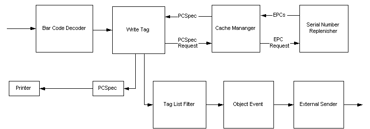
The following sequence summarizes the function of each component of the Tag Commissioning example:
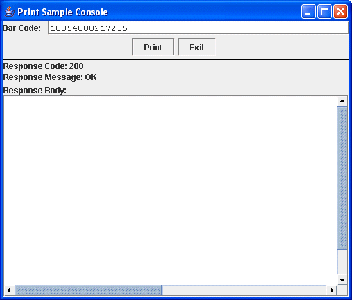
To run this example, the bar code GUI (invoked via run.bat), which is shown in Figure 2-16, sends the bar code you specify. The status area displays the response.
You must enter a bar code that conforms to one of the supported formats.


|