


|

|
|
|
|
Managing Transactions and Buffers
This section covers the following topics:
Transaction Management
Transaction management provides coordination for the completion of transactions, whether the transaction is successful or not. Application programmers can request the execution of remote services within a transaction, or users at remote domains can request the execution of local services within a transaction. Domains transaction management coordinates the mapping of remote transactions to local transactions, and the sane termination (commitment or rollback) of these transactions.
In the BEA Tuxedo system, a transaction tree is a two-level tree where the root is the group coordinating a global transaction and the branches are other groups on other machines that are involved in the transaction. Each group performs its part of the global transaction independently from the parts done by other groups. Each group, therefore, implicitly defines a transaction branch. If this BEA Tuxedo transaction branch is controlled by the eLink OSI TP domain, it may contain multiple actual OSI TP transaction branches. The eLink OSI TP gateway controls the mapping between the single BEA Tuxedo transaction root and the many OSI TP transaction branches. The BEA Tuxedo system uses Transaction Manager Servers (TMS) to coordinate the completion of the global transaction and make sure each branch completes.
Domains transaction management can be summarized as follows:
Tightly-Coupled and Loosely-Coupled Transactions
In the Open Group DTP Model, a Transaction Manager (TM) can construct transaction trees by defining either tightly-coupled or loosely-coupled relationships with a Resource Manager (RM). The coupling of the relationships are determined by the way the local service is defined in the DMCONFIG file.
A tightly-coupled relationship is one in which the same transaction identifier, XID, is used by all processes participating in the same global transaction and accessing the same RM. This relationship maximizes data sharing between processes; XA-compliant RMs expect to share locks for resources used by processes having the same XID.
The BEA Tuxedo system achieves the tightly-coupled relationship through the group concept; that is, work done by a group on behalf of a given global transaction belongs to the same transaction branch; all the processes are given the same XID. In a loosely-coupled relationship, the TM generates a transaction branch for each part of the work in support of the global transaction. The RM handles each transaction branch separately; there is no sharing of data or of locks between the transaction branches. Deadlocks between transaction branches can occur. A deadlock results in the rollback of the global transaction. In the BEA Tuxedo system, when different groups participate in the same global transaction each group defines a transaction branch; this results in a loosely-coupled relationship. The eLink OSI TP instantiation is user configurable and can provide a tightly-coupled integration that solves this deadlock problem by minimizing the number of transaction branches required in the interoperation between two domains.
Following are diagrams showing loosely-coupled and tightly-coupled integrations and an explanation of each diagram.
Figure 2-1 Example of a Tightly-Coupled Integration
The transaction tree for the tightly-coupled integration shown in Figure 2-1 eliminates the probability for intra-transaction deadlock by minimizing the number of transaction branches required in the interoperation between two domains. Application A makes three requests (r1, r2 and r3) to a remote Domain B. OSI TP sends all three requests mapped to the same OSI TP transaction, T1. On Domain B, the eLink OSI TP gateway checks the COUPLING flag for the remote service and discovers that for service B the COUPLING=TIGHT. In this case all requests for service B belong to the same BEA Tuxedo system transaction. Each request for service B is added to the previous requests and all will have the same BEA Tuxedo XID indicated by T2. Resources in group G1 will not be isolated and changes made by any instantiation of service B for this transaction will be "seen" by the others. Request r4 is mapped to identifier T2 on Domain B, but the Tuxedo domain generates a new branch in its transaction tree (r4: B to A'). This is a new transaction branch on Domain A, and therefore, the gateway generates a new mapping T3, to a new BEA Tuxedo system transaction. The gateway group on Domain A also coordinates group G4, so the hierarchical nature of inter-domain communication is fully enforced with this mapping; group G4 cannot commit before group G1. Figure 2-2 Example of a Loosely-Coupled Integration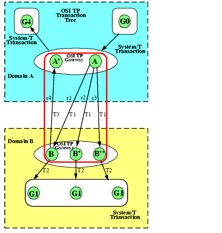
The transaction tree for the loosely-coupled integration shown in Figure 2-2 shows group G0 in Domain A coordinating the global transaction started by the client. In this case application A sends three requests (r1, r2, and r3) to a remote Domain B. Like the tightly-coupled case, all three branches are represented by OSI TP transaction T1. On Domain B, the eLink OSI TP gateway checks the COUPLING flag for the remote service and sees that service B is COUPLING=LOOSE. In this case, the eLink OSI TP gateway generates three BEA Tuxedo system transactions: T2, T3 and T4. Any changes made to G1 are isolated. For example, any changes made by service B can not be "seen" by service B'. When B calls back the A', a new transaction, T5, is generated. Global Transactions Across Domains A global transaction in a single BEA Tuxedo application follows a two-level transaction tree, but a global transaction across domains follows a more complex transaction tree. There are two reasons for this: 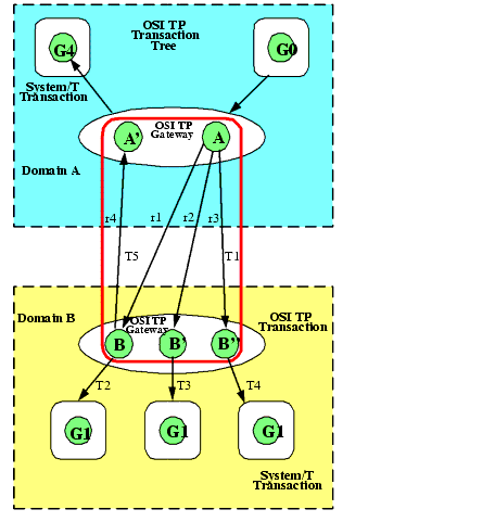
The commitment protocol across domains must be hierarchical to handle the complex transaction tree structure. For example, a loop-back service request is made from one domain (Domain A) to another domain (Domain B) and then comes back to be processed in the original domain. The service in Domain B requests another service in Domain A. The transaction tree has two branches at the network level: a branch b1 from A to B and a branch b2 from B to A. Domain A cannot commit the work done on branch b2 before receiving commit instructions from B.
The eLink OSI TP instantiation optimizes GTRID mapping by optionally implementing a tightly-coupled relationship. In eLink OSI TP, service requests issued on behalf of the same global transaction are mapped to the same network transaction branch. Therefore, incoming service requests can be mapped to a single BEA Tuxedo transaction. However, the hierarchical structure of inter-domain communication and the inter-domain transaction tree must still be maintained. See Figure 2-1 for an example of a tightly-coupled relationship.
The optimization that eLink OSI TP introduces applies only to a single domain. When two or more domains are involved in the transaction, the network transaction tree contains at least one branch per domain interaction. Therefore, across domains, the network transaction tree remains loosely-coupled. There will be as many branches as there are domains involved in the transaction (even if all branches access the same resource manager instance). Domains gateway groups implement a loosely-coupled relationship because they generate different transaction branches for inter-domain transactions.
See Figure 2-2 for an example of a loosely-coupled relationship. Notice that the gateway still must perform mappings between a BEA Tuxedo transaction and a network transaction, and that the hierarchical nature of the communication between domains must be strictly enforced. Figure 2-2 shows that requests r1, r2, and r3 are mapped to a single eLink OSI TP transaction branch. Therefore, on Domain B only one BEA Tuxedo transaction needs to be generated; request r4 is mapped to an identifier on Domain B, but eLink OSI TP generates a new branch in its transaction tree (r4: B to A'). This is a new transaction branch on Domain A, and therefore, the gateway generates a mapping to a new BEA Tuxedo transaction. The graph shows that gateway group GW on Domain A also coordinates group G4. Hence, the hierarchical nature of inter-domain communication is fully enforced with this mapping: group G4 cannot commit before group G1.
Transaction Recovery
OSI TP can recover an entire transaction of individual dialogues if one or more failures occur during the second phase of the two-phase commit process. Failures that occur before the second phase of commitment cause the transaction to roll back automatically. Three types of failure can occur after the second phase of commitment begins. For these types of failures, the following transaction recovery actions can occur:
Table 2-1 Transaction Recovery Actions for Failures
Buffer and Data Translation
The eLink OSI TP software uses typed buffers to transmit and receive data. Full buffer translation is supported for the following buffer types:
Note: Null X_OCTET buffers are not supported.
The following sections introduce procedures that eLink OSI TP follows to process and convert data buffers.
Layout Conversion for Buffer Types
XATMI (X/Open Application Transaction Manager Interface) mappings to OSI TP are defined in the XATMI ASE (Application Service Element). BEA eLink OSI TP supports this combination. Interoperability using eLink OSI TP requires that remote systems support XATMI ASE. Therefore, Tuxedo-specific buffer types, such as STRING, VIEW, FML, and CARRAY may need to be converted into XATMI standard types. BEA eLink OSI TP Gateways perform these layout conversions implicitly.
ASN.1 Encoding
Abstract Syntax Notation 1 (ASN.1) is an international standard that provides a canonical representation to deal with data representation differences such as byte order, word length, and character sets. The local gateway (GWOSITP) encodes input from the local client program. It produces an ASN.1 encoded record that is sent to the remote service. When a reply is received, it is decoded before being returned to the client. Similarly, when remote requests for local services are received by the local gateway, they are decoded from the ASN.1 format. Replies are then encoded for return to the remote client.
Buffers and Records
The following terms are used to describe input and output data:
These terms make it easier to understand how eLink OSI TP handles input and output data.
Buffers Received from Local Programs
The eLink OSI TP gateway processes buffers from local programs in the following manner.
The eLink OSI TP product automatically "types" input buffers that local client programs send to remote services.
The eLink OSI TP product automatically "types" output buffers that local services return to remote client programs.
Client requests sent to remote services may need to be converted to record formats that are meaningful to those services.
Server responses returned to remote client programs may need to be converted to record formats that are meaningful to those programs.
Records Received from Remote Programs
The eLink OSI TP gateway processes records from remote programs in the following manner.
Client requests from remote client programs may need to be converted to buffer formats that are acceptable to local service routines.
Server responses returned from remote services may need to be converted to buffer formats that are acceptable to local client programs.
Managing Parameters for Buffer and Record Conversion
The eLink OSI TP product provides four configuration parameters you can use to map buffers and records. These parameters are optional.
The following buffer configuration parameters are specified in the DM_LOCAL_SERVICES and/or the DM_REMOTE_SERVICES sections of the domain configuration file (DMCONFIG) as appropriate.
The definitions of these four parameters depend on whether the service requests originate locally or remotely. The following sections describe these parameters in relation to where the service request originates.
Parameters for Locally Originated Calls
This section describes in more detail how eLink OSI TP handles service calls that originate locally, within the immediate BEA Tuxedo region. It also explains how the INBUFTYPE, INRECTYPE, OUTRECTYPE, and OUTBUFTYPE parameters can be used to manage the conversion of buffers and records that flow between local client programs and remote services.
In the following figure, a local BEA Tuxedo client program issues a service call that a local eLink OSI TP gateway routes to a remote server through eLink OSI TP.
Figure 2-3 How Parameters Are Mapped During Locally Originated Calls
In this situation, the four configuration parameters that are shown in the figure have the following meanings: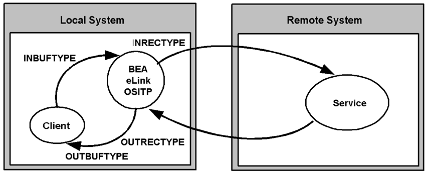
Guidelines for Mapping Input Buffers to Input Records
The following sections provide detailed information explaining how to use the INBUFTYPE and INRECTYPE parameters for service calls that originate locally (where local client programs call remote services).
Guidelines for Mapping Output Records to Output Buffers
The following sections provide detailed information explaining how to use the OUTRECTYPE and OUTBUFTYPE parameters for service calls that originate locally (where local client programs call remote services and receive output from those services).
Parameters for Remotely Originated Calls
This section describes how eLink OSI TP handles service calls that originate on remote computers, outside the local BEA Tuxedo region. It also explains how the INRECTYPE, INBUFTYPE, OUTBUFTYPE, and OUTRECTYPE parameters can be used to manage the conversion of buffers and records that flow between remote client programs and local services.
In the following figure, a remote client program issues a service request that a remote eLink OSI TP gateway routes to the local eLink OSI TP gateway. The gateway receives the request from the network and passes the request to a local BEA Tuxedo server.
Figure 2-4 How Parameters Are Mapped During Remotely Originated Calls
In this situation, the four configuration parameters that are shown in the figure have the following meanings: 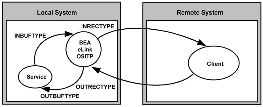
Guidelines for Mapping Input Records to Input Buffers
This section provides detailed information explaining how to use the INRECTYPE and INBUFTYPE parameters for service calls that originate on remote systems (where remote client programs call local services).
Guidelines for Mapping Output Buffers to Output Records
This section provide detailed information explaining how to use the OUTBUFTYPE and OUTRECTYPE parameters for service calls that originate on remote computers (where remote client programs call local services and receive output from those services).
Mapping Buffers to Records
The following figure shows all the possibilities for mapping buffers to records. The eLink OSI TP gateway is responsible for mapping buffers to records based on information it finds in the eLink OSI TP configuration. This mapping occurs for Tuxedo client requests and Tuxedo server responses.
Figure 2-5 Buffer to Record Mappings
Following are explanations about the mapping possibilities shown in the figure above and some suggestions for setting the INRECTYPE parameter. The INBUFTYPE parameter is only used for verification purposes and is not discussed here. 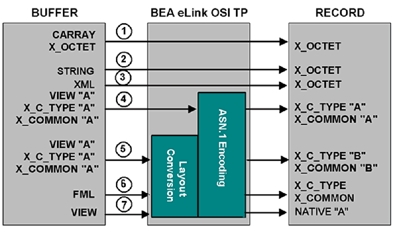
Note: If the source and target VIEW names are different, FML fields must be specified for all VIEW to VIEW conversions that eLink OSI TP performs (For example, VIEW=V10.V --> X_C_TYPE=V10.V does not require FML mapping fields). In other words, any VIEW that is to be used in a VIEW to different VIEW, VIEW to FML, or FML to VIEW conversion must be defined with appropriate FML fields (no dashes in the FNAME column of the VIEW definition). In order for the FML fields to match, you must compile the VIEWs without the -n option specified.
Mapping Records to Buffers
The following figure shows all the possibilities for mapping records to buffers. The eLink OSI TP gateway is responsible for mapping records to buffers, based on information it finds in the eLink OSI TP configuration. This mapping occurs for remote client requests and remote server responses.
Figure 2-6 Record to Buffer Mappings
Following are explanations about the mapping possibilities shown in the figure above and some suggestions for setting the OUTBUFTYPE parameter (for service calls that originate locally. These suggestions use the OUTBUFTYPE parameter, which controls data translation. 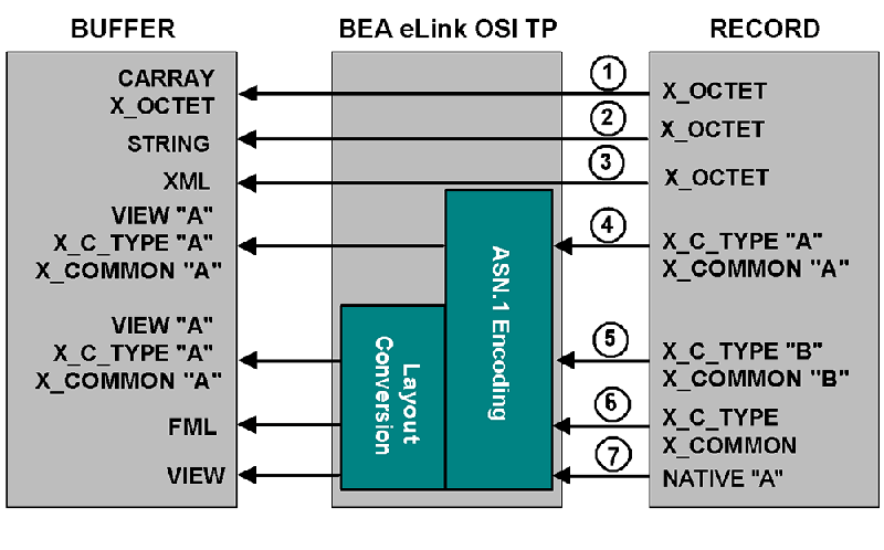
Note: FML Field definitions may be required to map VIEW 'B' to VIEW 'A'.
Note: FML fields must be specified for all FML to VIEW conversions that eLink OSI TP performs. In other words, any VIEW that is to be used in an FML to VIEW conversion must be defined with appropriate FML fields (no dashes in the FBNAME column of the VIEW definition). In order for the FML fields to match, you must compile the VIEWs without the -n option specified.
Special Cases and Examples of Buffer Conversion
Following are some examples of special cases and considerations for buffer conversion.
Examples:
INRECTYPE, of the remote service, must be configured to "VIEW" or "VIEW32", repectively.
INRECTYPE="FML:"/* ERROR */
OUTRECTYPE="FML32:"/* ERROR */
INBUFTYPE="FML:"
OUTBUFTYPE="FML32:"
Note: A colon is required at the end of keywords FML and FML32.
DMCONFIG Examples for Conversion to View32 and FML
In the following example, incoming buffer X_COMMON:v10 gets converted to VIEW:v12 before the request is sent to the service.
Listing 2-1 Conversion to View32
*DM_REMOTE_SERVICES
TOUPPER12
RDOM=DALNT2
LDOM=DALNT19220
PRIO=66
RNAME="TOUPPER12"
INBUFTYPE="X_COMMON:v10"
INRECTYPE="VIEW:v12"
In the following example, incoming buffer VIEW:v12 gets converted to FML, before the request is sent to the local service, and FML gets converted to X_C_TYPE:v16 before the reply is returned to the remote client.
Listing 2-2 Conversion to FML
*DM_LOCAL_SERVICES
OUTRECTYPE="VIEW:v12"
OUTBUFTYPE="FML:"
INBUFTYPE="FML:"
INRECTYPE="X_C_TYPE:v16"
For more information about FML, refer to the BEA Tuxedo Online Documentation athttp://download.oracle.com/docs/cd/E13203_01/tuxedo.
XML Buffer Support
BEA eLink OSI TP supports Tuxedo XML buffer types. XML buffers are treated like X_OCTET buffers because they are only passed through to the network. No data conversion is performed on the data.
XML buffers are passed to the remote domain as an XML data type unless converted to X_OCTET. If the remote domain does not support the XML data type, a decoding error occurs on the remote domain.

|

|

|
|
|
|
Copyright © 2001 BEA Systems, Inc. All rights reserved.
|