5 Oracle JCA Adapter for Sockets
This chapter describes how to use Oracle JCA Adapter for Sockets (Oracle Socket Adapter), which works with Oracle BPEL Process Manager (Oracle BPEL PM) and Oracle Mediator (Mediator) as an external service.
This chapter includes the following sections:
5.1 Introduction to Oracle Socket Adapter
Oracle Socket Adapter is a JCA 1.5 compliant adapter for modeling standard or nonstandard protocols for communication over TCP/IP sockets. You can use an Oracle Socket Adapter to create a client or a server socket, and establish a connection. The data that is transported can be text or binary.
This section includes the following topics:
-
Section 5.1.2, "Oracle Socket Adapter Integration with Mediator"
-
Section 5.1.3, "Oracle Socket Adapter Integration with Oracle BPEL PM"
-
Section 5.1.4, "Oracle Socket Adapter Integration with SOA Composite"
5.1.1 Oracle Socket Adapter Architecture
Oracle Socket Adapter is based on the JCA 1.5 architecture. JCA provides a standard architecture for integrating heterogeneous enterprise information systems (EIS). The JCA Binding Component of the Oracle Socket Adapter exposes the underlying JCA interactions as services (WSDL with JCA binding) for Oracle BPEL PM integration. Figure 5-1 illustrates the architecture of Oracle Socket Adapter. For details about the Oracle JCA Adapter architecture, see Section 1.2.1.1, "Architecture."
Figure 5-1 Oracle Socket Adapter Architecture
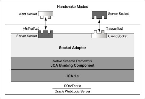
Description of "Figure 5-1 Oracle Socket Adapter Architecture"
5.1.2 Oracle Socket Adapter Integration with Mediator
Oracle Socket Adapter is automatically integrated with Mediator. When you create an Oracle Socket Adapter service in JDeveloper Designer, the Adapter Configuration Wizard is started. This wizard enables you to configure the Oracle Socket Adapter. When configuration is complete, a WSDL file of the same name is created in the Application Navigator section of Oracle JDeveloper (JDeveloper). This WSDL file contains the configuration information you specify in the Adapter Configuration Wizard.
The Operation Type page of the Adapter Configuration Wizard prompts you to select an operation to perform. Based on your selection, different Adapter Configuration Wizard pages appear and prompt you for configuration information.
For more information about Oracle JCA Adapter integration with Mediator, see Section 3.2, "Adapter Integration with Oracle Fusion Middleware."
5.1.3 Oracle Socket Adapter Integration with Oracle BPEL PM
Oracle Socket Adapter is automatically integrated with Oracle BPEL PM. When you drag and drop Socket Adapter from the Component Palette of JDeveloper BPEL Designer, the Adapter Configuration Wizard starts with a Welcome page, as shown in Figure 5-2.
Figure 5-2 The Adapter Configuration Wizard - Welcome Page
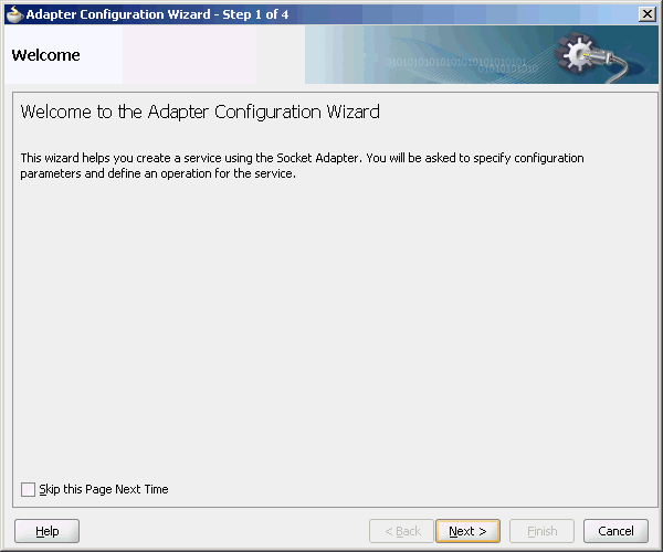
Description of "Figure 5-2 The Adapter Configuration Wizard - Welcome Page"
This wizard enables you to configure an Oracle Socket Adapter. The Adapter Configuration Wizard then prompts you to enter a service name, as shown in Figure 5-3.
Figure 5-3 The Adapter Configuration Wizard Service Name Page
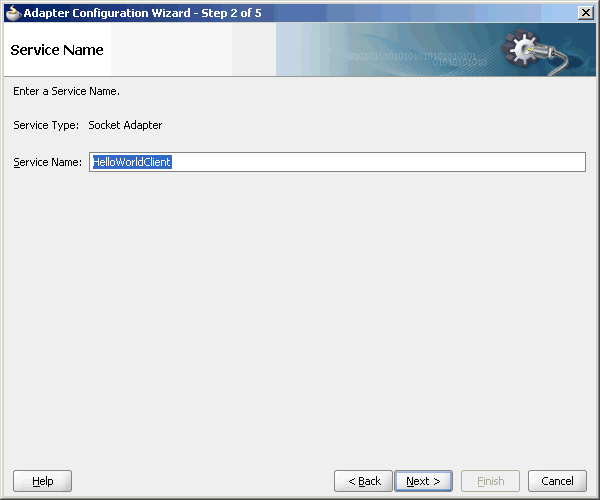
Description of "Figure 5-3 The Adapter Configuration Wizard Service Name Page"
When configuration is complete, a WSDL file of the same name is created in the Application Navigator section of JDeveloper. This WSDL file contains the configuration information you specify in the Adapter Configuration Wizard.
The Operation Type page of the Adapter Configuration Wizard prompts you to select an operation to perform. Based on your selection, different Adapter Configuration Wizard pages appear and prompt you for configuration information.
For more information about Oracle JCA Adapter integration with Oracle BPEL PM, see Section 3.2, "Adapter Integration with Oracle Fusion Middleware."
5.1.4 Oracle Socket Adapter Integration with SOA Composite
A composite is an assembly of services, service components (Oracle BPEL PM and Mediator), wires, and references designed and deployed in a single application. The composite processes the information described in the messages. The details of the composite are stored in the composite.xml file. For more information on integration of the Oracle Socket Adapter with SOA composite, see Section 3.2.4, "Oracle SOA Composite Integration with Adapters."
5.2 Oracle Socket Adapter Features
Oracle Socket Adapter enables you to configure a BPEL process or a Mediator service to read and write data over TCP/IP sockets. It includes the following features:
-
Allows modeling of standard or nonstandard protocols for communication over TCP/IP sockets
-
Supports both inbound and outbound communication
-
Allows you to model complex protocol handshakes declaratively, by using XSL
-
Allows you the option of plugging in custom Java code to model a protocol handshake
-
Provides support for reading and writing native data over sockets as the adapter is integrated with the translator infrastructure (NXSD)
-
Supports multiple character encoding
5.3 Oracle Socket Adapter Concepts
This section describes the following Oracle Socket Adapter concepts:
5.3.1 Communication Modes
Oracle Socket Adapter supports inbound and outbound communication over sockets that can be unidirectional or bidirectional. The communication modes of Oracle Socket Adapter are discussed in the following sections:
5.3.1.1 Inbound Synchronous Request/Response
As part of inbound activation, the Oracle Socket Adapter opens a server socket and waits for incoming connections. The adapter uses the connection to the server socket and reads the request message, which is published to BPEL or Mediator. The Oracle Socket Adapter then uses the same connection to send the response back synchronously.
Figure 5-4 illustrates an inbound synchronous request/response scenario.
Figure 5-4 BPEL Scenario of Inbound Synchronous Request/Response
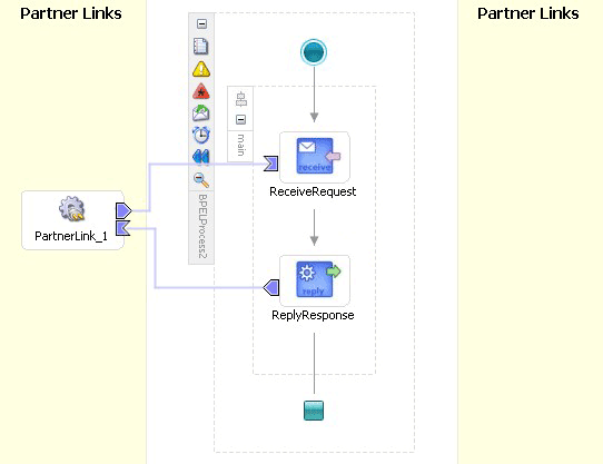
Description of "Figure 5-4 BPEL Scenario of Inbound Synchronous Request/Response"
5.3.1.2 Outbound Synchronous Request/Response
In the case of outbound synchronous request/response, a request comes from BPEL or Mediator. The Oracle Socket Adapter connects to the server socket to send the request message to the server socket on the output stream. The Oracle Socket Adapter then blocks the response from the server socket on the input stream and publishes the response back to BPEL or Mediator.
Figure 5-5 illustrates an outbound synchronous request/response scenario.
Figure 5-5 BPEL Scenario of Outbound Synchronous Request/Response
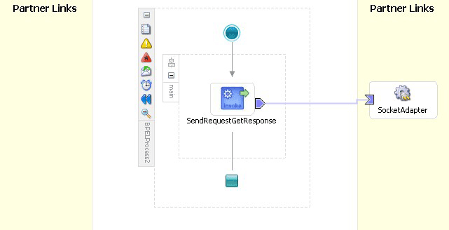
Description of "Figure 5-5 BPEL Scenario of Outbound Synchronous Request/Response"
5.3.1.3 Inbound Receive
As part of inbound activation, the Oracle Socket Adapter opens a server socket and waits for incoming connections. The adapter uses the connection to the server socket and reads the request message, which is published to BPEL or Mediator. In this scenario, no reply is sent.
5.3.2 Mechanisms for Defining Protocols
Communication protocols or handshakes consist of different discrete steps such as authentication procedures, acknowledgments, and sending or receiving data depending on conditions. Oracle Socket Adapter supports the following mechanisms to define the protocol handshakes.
5.3.2.1 Protocol with Handshake Mechanism Using Style Sheet
Oracle Socket Adapter can be configured to use a protocol designed with a handshake mechanism, defined using style sheets that use XPath Extension functions exposed by the adapter. This can be granular read and write operation on the socket I/O stream or till the end of the stream. These functions also enable you to use native format constructs for reading and writing data. This handshake mechanism uses XSLT constructs to define operations such as assignments, validations, and control flow.
You can use the XPath Extension functions with the translator infrastructure in the following ways:
-
By using StyleReader, which is exposed by the NXSD framework, to read and write from the socket stream using the following methods:
-
socketRead(nxsdStyle:String, nxsdStyleAttributes:String):StringYou can use this method to read from the socket input stream.
-
socketWrite(value:String, nxsdStyle:String, nxsdStyleAttributes:String):StringYou can use this method to write to the socket output stream.
The XSLT shown in Figure 5-6 demonstrates the usage of extension functions that use StyleReader.
Figure 5-6 XSLT with Extension Functions That Use StyleReader
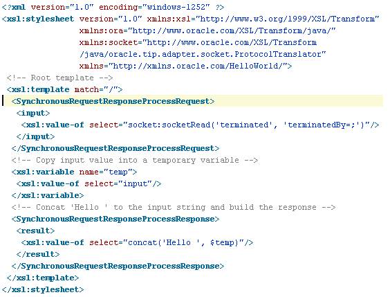
Description of "Figure 5-6 XSLT with Extension Functions That Use StyleReader"
-
-
By annotating the schema, which defines the input and output variables, using NXSD constructs to read and write from the socket stream using the following methods:
-
socketReadWithXlation():DocumentFragmentYou can use this method to read from the socket input stream by using the schema and schema element configured for input.
-
socketWriteWithXlation(xml:NodeList)You can use this method to write to the socket output stream by using the schema configured for output.
The XSD file shown in Figure 5-7 demonstrates the usage of extension functions by annotating the schema, which defines the input and output variables, using NXSD constructs.
Figure 5-7 XSD with Extension Functions That Do Not Use StyleReader
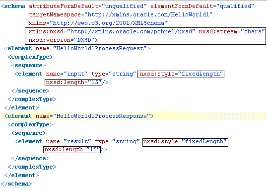
Description of "Figure 5-7 XSD with Extension Functions That Do Not Use StyleReader"
-
To define a handshake using style sheet, you must select Use XSLT to define the handshake and browse to select the XSL file in the Protocol page, as shown in Figure 5-8.
Figure 5-8 Defining a Protocol with Handshake Mechanism By Using a Style Sheet
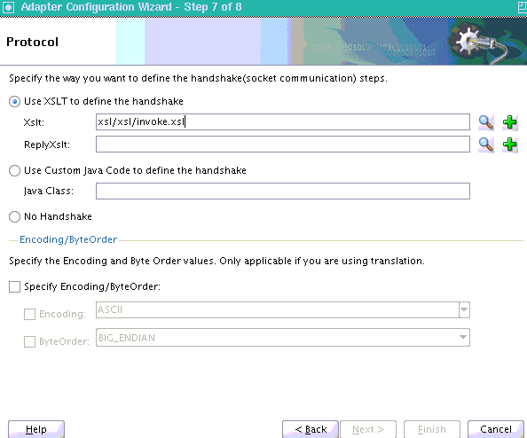
Description of "Figure 5-8 Defining a Protocol with Handshake Mechanism By Using a Style Sheet"
5.3.2.2 Protocol with Handshake Mechanism Using Custom Java Code
Oracle Socket Adapter can be configured to use a protocol with a customized handshake mechanism, defined by plugging in custom Java code. The custom Java code must implement oracle.tip.pc.services.translation.util.ICustomParser, the ICustomParser interface, provided by Oracle Socket Adapter, which enables custom implementation of handshakes.
Note:
The ICustomParser interface files are in thebpm-infra.jar file. This jar file is available in the following directory:
$SOA_ORACLE_HOME/soa/modules/oracle.soa.fabric_11.1.1
The following methods must be implemented based on the appropriate communication paradigm:
-
public Element executeOutbound(InputStream in, OutputStream out, Element payLoad) throws Exception;The outbound handshake must implement this method.
Example:
public Element executeOutbound(InputStream in, OutputStream out, Element payLoad) throws Exception { BufferedReader in1 = new BufferedReader(new InputStreamReader(in)); PrintWriter out1 = new PrintWriter(new OutputStreamWriter(out)); out1.println(payLoad.getFirstChild().getNodeValue()); String retVal = in1.readLine(); StringBuffer strBuf = new StringBuffer(); strBuf.append("<?xml version='1.0' encoding='" + enc + "' ?>" + "<out xmlns='http://xmlns.oracle.com/EchoServer/'>"); strBuf.append(retVal + "</out>"); DOMParser parser = new DOMParser(); parser.setValidationMode(DOMParser.NONVALIDATING); Element elem = (Element) parser.getDocument().getElementsByTagName( "out").item(0); return elem; } -
public Element executeInboundRequest(InputStream in) throws Exception;The inbound request must implement this method.
Example:
public Element executeInboundRequest(InputStream in) throws Exception { BufferedReader in1 = new BufferedReader(new InputStreamReader(in)); String input = in1.readLine(); StringBuffer strBuf = new StringBuffer(); strBuf.append("<?xml version='1.0' encoding='" + enc + "' ?>" + "<EchoClientProcessRequest xmlns='http://xmlns.oracle.com/EchoClient'>"); strBuf.append("<input>" + input + "</input></EchoClientProcessRequest>"); DOMParser parser = new DOMParser(); parser.setValidationMode(DOMParser.NONVALIDATING); parser.parse(new InputSource(new StringReader(strBuf.toString()))); Element elem = (Element) parser.getDocument().getElementsByTagName( "EchoClientProcessRequest").item(0); return elem; } -
public void executeInboundReply(Element payLoad, OutputStream out) throws Exception;The inbound reply must implement this method.
Example:
public void executeInboundReply(Element payLoad, OutputStream out) throws Exception {
    PrintWriter out1 = new PrintWriter(new OutputStreamWriter(out));

    NodeList list = payLoad.getChildNodes();
    String retVal = null;
    for(int i = 0; i < list.getLength(); i++) {
        Node node = list.item(i);
        NodeList list1 = node.getChildNodes();
        for(int j = 0; j < list1.getLength(); j++) {
            Node node1 = list1.item(j);
            if(node1.getNodeType() == Node.TEXT_NODE) {
                    retVal = node1.getNodeValue();
            }
        }
    }
    out1.println(retVal);
    out1.flush();
}
Note:
in is the handle to the socket input stream and out is the handle to the socket output stream.To use a custom Java code to define a handshake, you must select Use Custom Java Code to define the handshake and specify the Java class implementing the handshake in the Java Class field, as shown in Figure 5-9.
Figure 5-9 Defining a Protocol with Handshake Mechanism By Using Custom Java Code
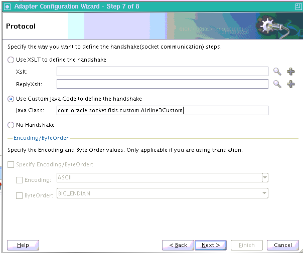
Description of "Figure 5-9 Defining a Protocol with Handshake Mechanism By Using Custom Java Code"
5.3.2.3 Protocol Without Handshake Mechanism
Oracle Socket Adapter can be configured to use protocols that do not require handshakes involving translation to and from the socket I/O stream.
To use a protocol that does not require a handshake, you must select No Handshake in the Protocol page, as shown in Figure 5-10.
Figure 5-10 Defining a Protocol without a Handshake Mechanism
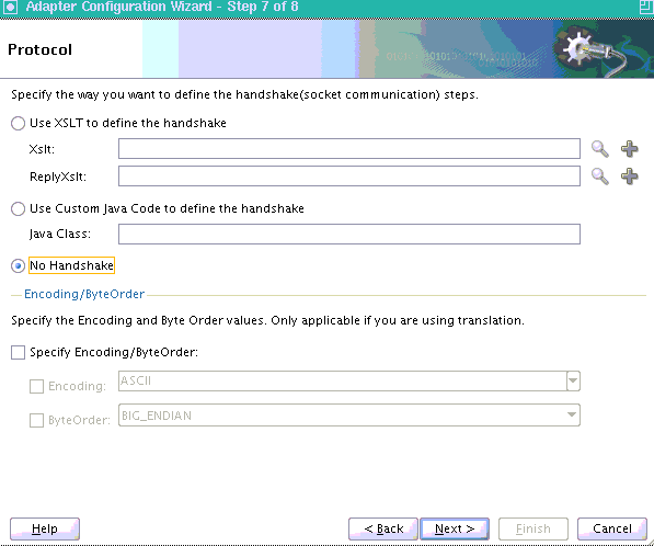
Description of "Figure 5-10 Defining a Protocol without a Handshake Mechanism"
5.3.3 Character Encoding and Byte Order
The Encoding property represents the character encoding in which native data is stored, and the ByteOrder property is the byte order of the native data, which is either BIG_ENDIAN or LITTLE_ENDIAN.
Character encoding and byte order can be specified in the schema file (NXSD), using the Native Format Builder wizard. You can also specify the encoding and the byte order to be used, by using the Adapter Configuration Wizard. When encoding and byte order are not specified, the default values are US-ASCII and BIG_ENDIAN.
To specify the encoding and byte order values, which are applicable only if you are using translation, you must perform the following steps in the Protocol page of the Adapter Configuration Wizard:
-
In the Encoding/ByteOrder section of the Protocol page, select the Specify Encoding/Byte Order option, as shown in Figure 5-11.
Figure 5-11 The Adapter Configuration Wizard - Protocol Page
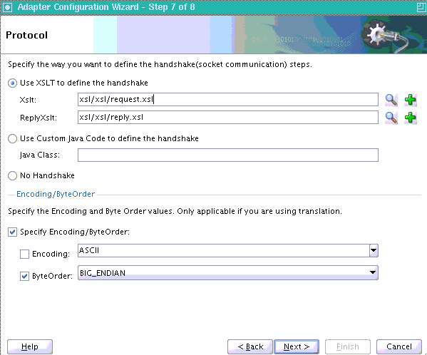
Description of "Figure 5-11 The Adapter Configuration Wizard - Protocol Page"
-
Perform one of these tasks to set the encoding:
-
To use the encoding specified in the schema file, leave Encoding unchecked.
-
To specify the encoding using the Adapter Configuration Wizard, select Encoding, and then select an encoding type from the Encoding list.
Note:
If you select Encoding, then the encoding type specified using the Adapter Configuration Wizard takes precedence over the encoding type specified in the NXSD file.
-
-
Perform one of these tasks to set the byte order:
-
To use the byte order specified in the schema file, select Use Byte Order Value from the schema.
-
To specify the byte order using the Adapter Configuration Wizard, select ByteOrder, and then select a byte order from the ByteOrder list.
-
-
Click Finish.
Once you click Finish, the Configuration Wizard displays a page that indicates that you have finished configuring the Socket Adapter.
5.3.4 Performance Tuning
The Oracle Socket Adapter supports performance tuning features, including:
For more information about performance tuning, see "Oracle Socket Adapter Tuning" in the Oracle Fusion Middleware Performance and Tuning Guide.
5.3.4.1 Configuring Oracle Socket Adapter Connection Pooling
One way to optimize Oracle Socket Adapter performance is by using a Connection Pool. You can use a connection pool while the socket server you are connecting to does not close the socket with each interaction. A connection pool lets you use a socket connection repeatedly, avoiding the overhead of creating a new socket for each interaction. You must configure the connection pool for the Oracle Socket Adapter using the Oracle WebLogic Server console.
Note:
The Connection Pool feature is applicable to outbound interactions only.How to configure Oracle Socket Adapter connection pooling:
-
Log into your Oracle WebLogic Server console. To access the console navigate to
http://servername:portnumber/console. -
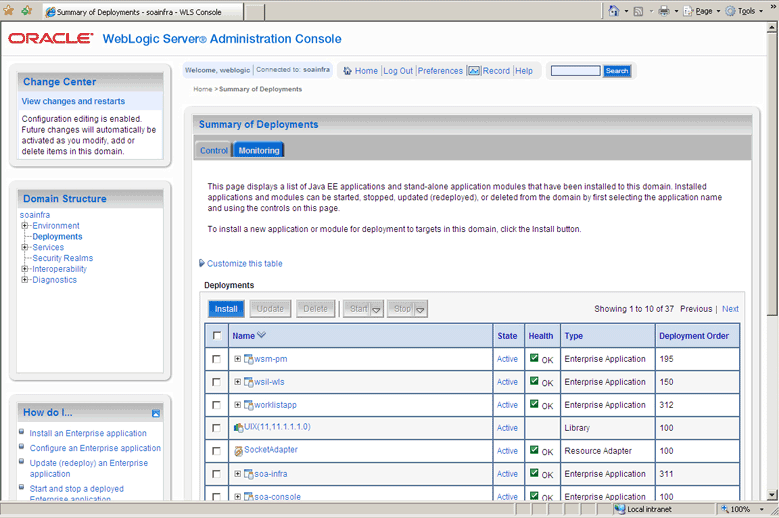
Click Deployments in the left pane for Domain Structure. The Summary of Deployments page is displayed.
Figure 5-12 Oracle WebLogic Server Console - Summary of Deployments Page
Description of "Figure 5-12 Oracle WebLogic Server Console - Summary of Deployments Page"
-
Click SocketAdapter. The Settings for SocketAdapter page is displayed.
-
Click the Configuration tab.
-
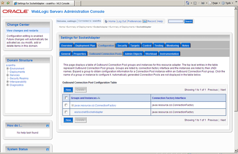
Click the Outbound Connection Pools tab, and expand javax.resource.cci.ConnectionFactory to see the configured connection factories, as shown in Figure 5-13:
Figure 5-13 Oracle WebLogic Server Console - Settings for SocketAdapter Page
Description of "Figure 5-13 Oracle WebLogic Server Console - Settings for SocketAdapter Page"
-
Click eis/socket/SocketAdapter. The Settings for javax.resource.cci.ConnectionFactory page is displayed.
-
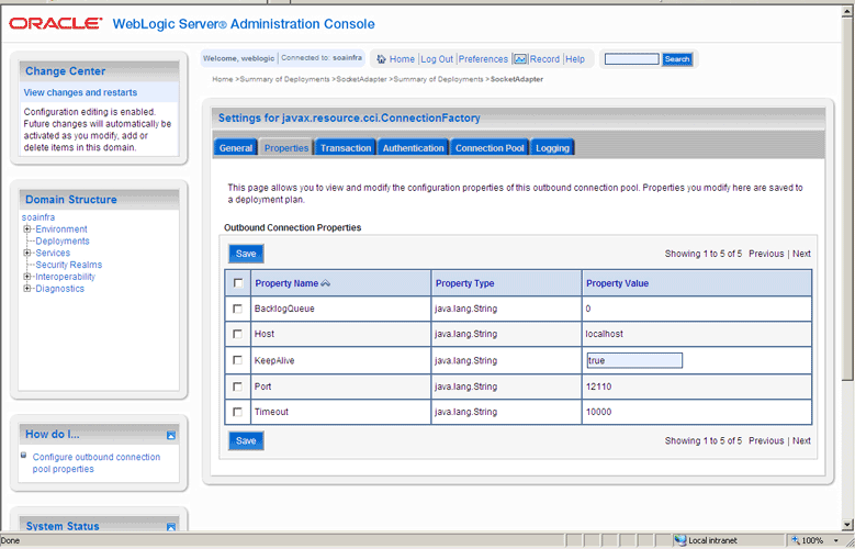
Set the
KeepAliveconnection factory property totrue, as shown in Figure 5-14. The connection pool feature for the Oracle Socket Adapter is enabled.Figure 5-14 Oracle WebLogic Server Console - Settings for javax.resource.cci.Connectionfactory Page
Description of "Figure 5-14 Oracle WebLogic Server Console - Settings for javax.resource.cci.Connectionfactory Page"
-
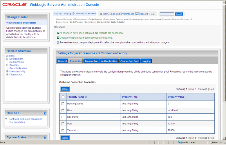
Click Save. The Settings for javax.resource.cci.ConnectionFactory page is displayed with the message,
Deployment plan has been successfully updated, as shown in Figure 5-15.Figure 5-15 Oracle WebLogic Server Console - Settings for javax.resource.cci.Connectionfactory Page
Description of "Figure 5-15 Oracle WebLogic Server Console - Settings for javax.resource.cci.Connectionfactory Page"
Note:
You can modify connection pool parameters by using the Connection Pool tab of Oracle WebLogic Server Administration Console.5.4 Configuring Oracle Socket Adapter
The following tasks are required for configuring Oracle Socket Adapter:
-
Specifying a TCP Port in a Configuration Plan For an Oracle Socket Adapter
5.4.1 Modifying the weblogic-ra.xml File
To configure Oracle Socket Adapter, you must specify the value of the properties listed in Table 5-1 in the weblogic-ra.xml file. You can update these properties from the Oracle WebLogic Server Administration Console. For more information, see Section 2.18, "Adding an Adapter Connection Factory."
Table 5-1 Oracle Socket Adapter Configuration Properties
| Property | Description |
|---|---|
|
Host |
In case of outbound interaction, the system name on which the socket server is running, to which you want to connect. In case of inbound interaction, it is always |
|
Port |
In case of outbound interaction, it is the port number on which a socket server is running, to which an adapter connects. In case of inbound interaction, it is the port number on which the socket adapter listens for incoming connections. |
|
Timeout |
With this value set to a nonzero timeout interval, a |
|
KeepAlive |
Applicable only in case of outbound interactions. Should be set to |
|
BacklogQueue |
Applicable in case of inbound interactions. This value indicates the maximum queue length for incoming connection indications (a request to connect). If a connection indication arrives when the queue is full, then the connection is refused. |
The following is a sample weblogic-ra.xml file:
<wls:connection-instance>
                <wls:description>Socket Adapter</wls:description>
                <wls:jndi-name>eis/socket/SocketAdapter</wls:jndi-name>
                <wls:connection-properties>
                    <wls:pool-params>
                        <wls:initial-capacity>0</wls:initial-capacity>
                        <wls:max-capacity>200</wls:max-capacity>
                        <wls:capacity-increment>5</wls:capacity-increment>
                        <wls:shrinking-enabled>true</wls:shrinking-enabled>

<wls:shrink-frequency-seconds>60</wls:shrink-frequency-seconds>

<wls:connection-creation-retry-frequency-seconds>2</wls:connection-creation-retry
-frequency-seconds>

<wls:connection-reserve-timeout-seconds>5</wls:connection-reserve-timeout-seconds>

<wls:match-connections-supported>true</wls:match-connections-supported>
                        <wls:use-first-available>true</wls:use-first-available>
                    </wls:pool-params>

<wls:transaction-support>NoTransaction</wls:transaction-support>

<wls:reauthentication-support>true</wls:reauthentication-support>
                    <wls:properties>
                        <wls:property>
                            <wls:name>Host</wls:name>
                            <wls:value>localhost</wls:value>
                        </wls:property>
                        <wls:property>
                            <wls:name>Port</wls:name>
                            <wls:value>12110</wls:value>
                        </wls:property>
                        <wls:property>
                            <wls:name>Timeout</wls:name>
                            <wls:value>10000</wls:value>
                        </wls:property>
                        <wls:property>
                            <wls:name>BacklogQueue</wls:name>
                            <wls:value>0</wls:value>
                        </wls:property>
                        <wls:property>
                            <wls:name>KeepAlive</wls:name>
                            <wls:value>True</wls:value>
                        </wls:property>
                    </wls:properties>
                    <wls:res-auth>Application</wls:res-auth>
                </wls:connection-properties>
            </wls:connection-instance>
Note:
To set up connection pooling, you must set theKeepAlive property to true.5.4.2 Modeling a Handshake
A handshake may be required to negotiate a connection with a client or a server socket.
5.4.2.1 Modeling an Outbound Handshake
The outbound XSLT uses an input corresponding to the invoked message. The outbound XSLT writes to the socket output stream by using extension functions. The output is dummy for unidirectional or a response for bidirectional communication.
The following example demonstrates the modeling of a Synchronous Request/Response communication paradigm:
<xsl:stylesheet
...
xmlns:socket="http://www.oracle.com/XSL/Transform/java/oracle.tip.adapter.socket.ProtocolTranslator" />
xmlns:request="http://www.TragetNameSpace.com/Request" >

  <xsl:template match="/">

    <!–- Write the entire content of "books" element using translator -->
    <xsl:variable name="username" select="socket:socketWriteWithXlation(.)" />

    <!–- Read the stream using translator -->
    <xsl:copy-of select="socket:socketReadWithXlation()" />

  </xsl:template>
</xsl:stylesheet>
5.4.2.2 Modeling an Inbound Handshake
The inbound XSLT uses a dummy input, reads the socket input stream through extension functions, and constructs the XML record to be published.
The following example demonstrates a handshake in which the client sends across a user identification terminated by a comma (,) and a password terminated by a semicolon (;) for validation, and then sends the message payload:
<xsl:stylesheet
...
xmlns:socket="http://www.oracle.com/XSL/Transform/java/oracle.tip.adapter.socket.ProtocolTranslator" />
  <xsl:template match="/">
    <!-- Read the user name -->
    <xsl:variable name="username"
select="socket:socketRead('terminated','terminatedBy=,')" />
    <!-- Read password if user name is correct -->
    <xsl:if test="normalize-space($username)='user'">
      <xsl:variable name="password"
select="socket:socketRead('terminated','terminatedBy=;')" />
      <!-- If password is correct proceed to read the payload using translator
-->
      <xsl:if test="normalize-space($password)='password'">
        <!--  Send an OK -->
        <xsl:variable name="ack1" select="socket:socketWrite('001','','')" />

        <output>
<!--  Wait for the payload -->
          <xsl:copy-of select="socket:socketReadWithXlation()" />
        </output>

      </xsl:if>
      <!--  Send an error -->
      <xsl:else><xsl:variable name="ack2"
select="socket:socketWrite('000','','')" /></xsl:else>
    </xsl:if>
  </xsl:template>
</xsl:stylesheet>
5.4.3 Designing an XSL File Using the XSL Mapper Tool
You can design an XSL file by using the XSL mapper tool for Oracle Socket Adapter. The following sections describe the procedure for designing XSL for different communication scenarios:
-
Section 5.4.3.1, "Designing XSL for Inbound Synchronous Request/Reply"
-
Section 5.4.3.2, "Designing XSL for Outbound Synchronous Request/Reply"
5.4.3.1 Designing XSL for Inbound Synchronous Request/Reply
This section describes the procedure for designing XSL for an inbound synchronous request/reply scenario by using the XSL mapper tool:
Note:
To perform this use case, you require the following files from theartifacts.zip file contained in the Adapters-101SocketAdapterHelloWorld sample:
-
artifacts/schemas/HelloWorld.xsd
You can access the Adapters-101SocketAdapterHelloWorld sample on the Oracle SOA Sample Code site.
Copy this file to the HelloWorldComposite\xsd folder under the HelloWorldComposite project.
To design an SOA composite, perform the steps described in Section 5.5.1.2, "Designing the SOA Composite."
Note:
The steps provided in Section 5.5.1.2, "Designing the SOA Composite" are applicable to a composite with Oracle BPEL PM. Alternatively, you can create a composite with Mediator.Create an Inbound Oracle Socket Adapter Service
To create an inbound Oracle Socket Adapter service, perform the following steps:
-
Drag and drop Socket Adapter from the Components Palette to the Exposed Services swim lane. The Welcome page of the Adapter Configuration Wizard is displayed.
-
Click Next. The Service Name page is displayed.
-
Enter the service name,
HelloWorldin the Service Name field and then click Next. The Adapter Interface page is displayed. -
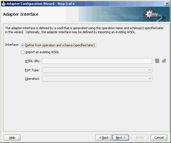
Select Define from operation and schema (specified later), as shown in the Figure 5-16, and click Next. The Operation page is displayed.
Figure 5-16 The Adapter Configuration Wizard - Adapter Interface Page
Description of "Figure 5-16 The Adapter Configuration Wizard - Adapter Interface Page"
-
Select Inbound Synchronous Request/Reply as the Operation Type and then click Next. The Socket Connection page is displayed.
-
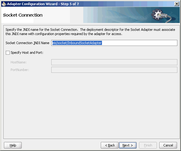
Enter
eis/socket/InboundSocketAdapterin the Socket Connection JNDI Name field, as shown in Figure 5-17, and click Next. The Messages page is displayed.Figure 5-17 The Adapter Configuration Wizard Socket Connection Page
Description of "Figure 5-17 The Adapter Configuration Wizard Socket Connection Page"
-
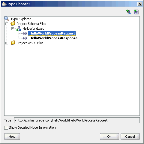
Click Browse For Schema File that appears at the end of the URL field in the Request Message Schema box. The Type Chooser dialog is displayed.
-
Click Project Schema Files, HelloWorld.xsd, and HelloWorldProcessRequest, as shown in Figure 5-18.
-
Click OK. The URL field in the Messages page is populated with the HelloWorld.xsd file.
-
Click Browse For Schema File that appears at the end of the URL field in the Reply Message Schema box. The Type Chooser dialog is displayed.
-
Click Project Schema Files, HelloWorld.xsd, and HelloWorldProcessResponse.
-
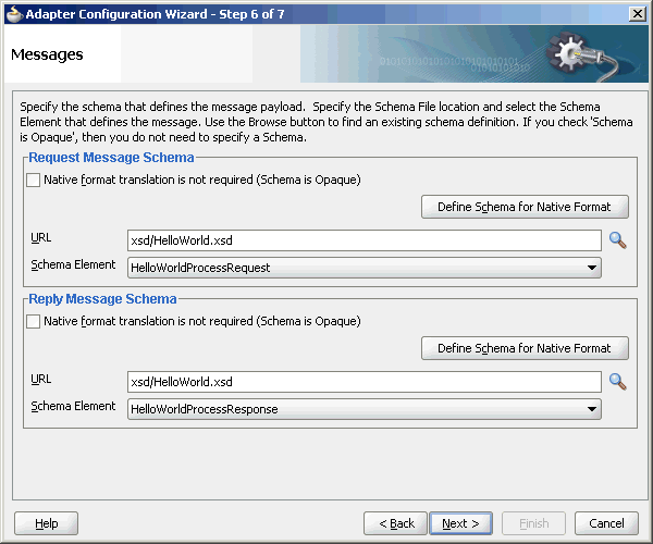
Click OK. The URL fields in the Messages page are populated with the HelloWorld.xsd files, as shown in Figure 5-19.
Figure 5-19 The Adapter Configuration Wizard File Messages Page
Description of "Figure 5-19 The Adapter Configuration Wizard File Messages Page"
-
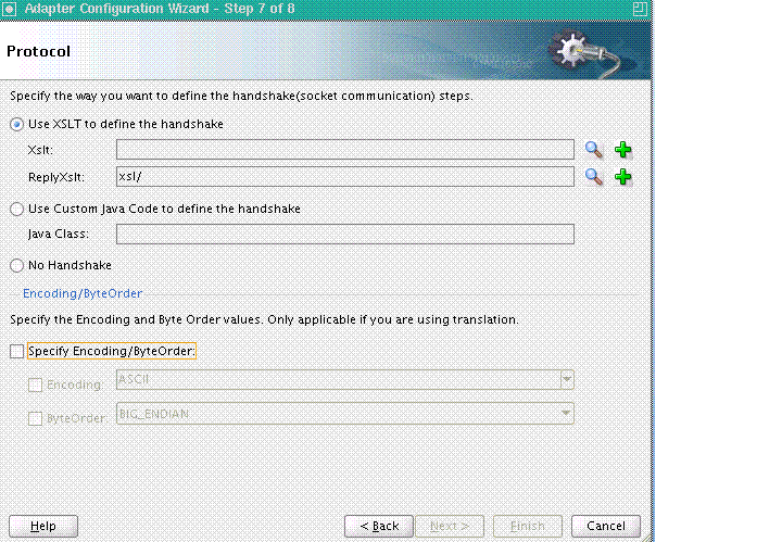
Click Next. The Protocol page is displayed, as shown in Figure 5-20.
Figure 5-20 The Adapter Configuration Wizard - Protocol Page
Description of "Figure 5-20 The Adapter Configuration Wizard - Protocol Page"
-
Select Use XSLT to define the handshake.
-
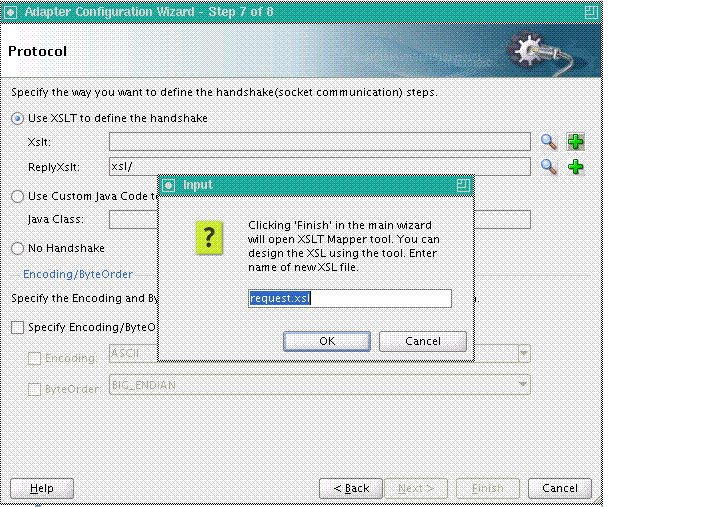
Click the create new xsl file icon that appears at the end of the Xslt field. The Input dialog appears, as shown in Figure 5-21.
Figure 5-21 The input Dialog of the Protocol Page
Description of "Figure 5-21 The input Dialog of the Protocol Page"
-
Use the default value, request.xsl, as the name of the XSL file, as shown in Figure 5-21 and click OK.
-
Click the create new xsl file icon that appears at the end of the ReplyXslt field. The Input dialog appears.
-
Use the default value, reply.xsl, as the name of the XSL file, and click OK.
-
Click Finish. The request.xsl and the reply.xsl files are created.
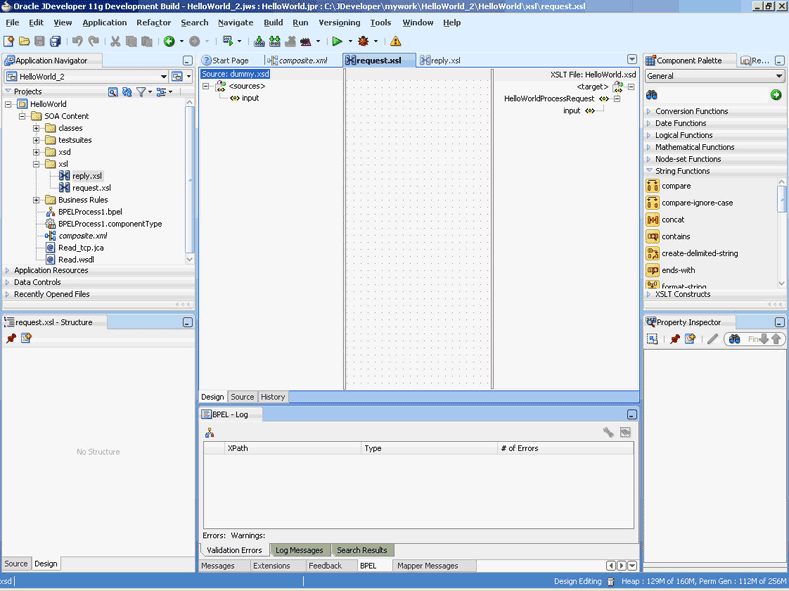
Figure 5-22 shows the request.xsl page.
Figure 5-22 The JDeveloper - request.xsl Page
Description of "Figure 5-22 The JDeveloper - request.xsl Page"
Note:
Adummy.xsdfile appears in the left Source pane of therequest.xslpage, which is used as the source for the XSL mapper tool.In an inbound request scenario, Oracle Socket Adapter reads native data that is received by the socket and converts it to an XML format. That is, on the source side there is no XML file. Because the XSLT mapper always needs source and target XSD files, a dummy XSD file appears in the mapper tool.
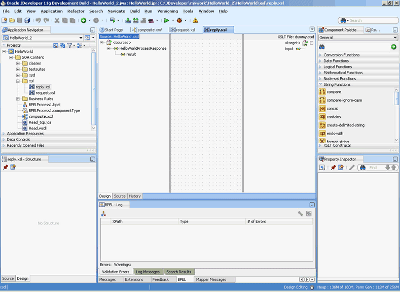
Figure 5-23 shows the reply.xsl page.
Figure 5-23 The JDeveloper - reply.xsl Page
Description of "Figure 5-23 The JDeveloper - reply.xsl Page"
Note:
Adummy.xsdfile appears in the right target pane of thereply.xslpage. Thisdummy.xsdfile is used as the target for the XSL mapper tool. -
Define the request part of the inbound synchronous request/reply operation as follows:
-
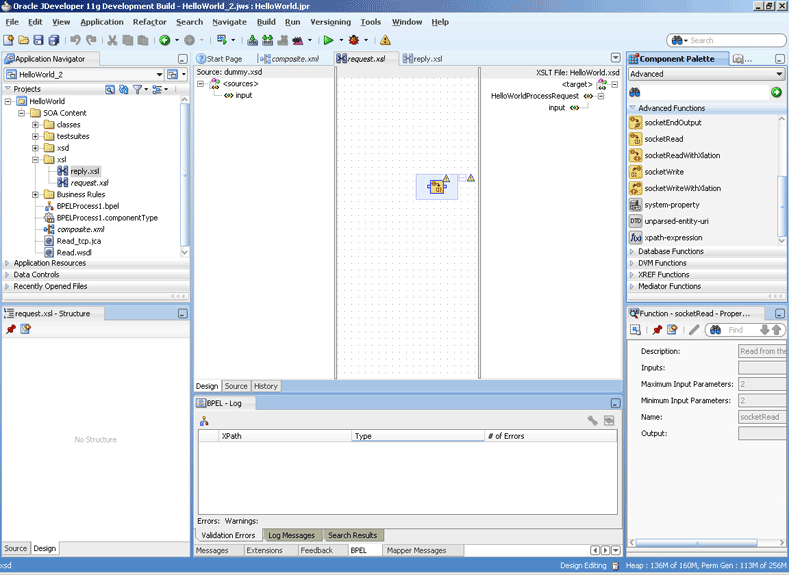
In the request.xsl page, drag and drop socketRead from the Advanced Functions list of the Components Palette to the middle pane, as shown in Figure 5-24.
Figure 5-24 The JDeveloper - request.xsl Page
Description of "Figure 5-24 The JDeveloper - request.xsl Page"
-
Double-click the socketRead advanced function. The Edit Function - socketRead dialog appears.
-
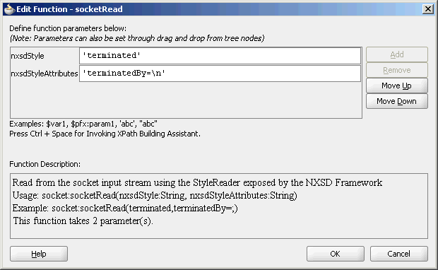
Enter the function parameters in the nxsdStyle and nxsdStyleAttributes fields, as shown in Figure 5-25.
Figure 5-25 The Edit Function - socketRead Dialog
Description of "Figure 5-25 The Edit Function - socketRead Dialog"
Note:
ThesocketReadfunction reads from the socket input stream by using theStyleReaderexposed by the NXSD framework. -
Click OK. The request.xsl (XSL mapper tool) page is displayed.
-
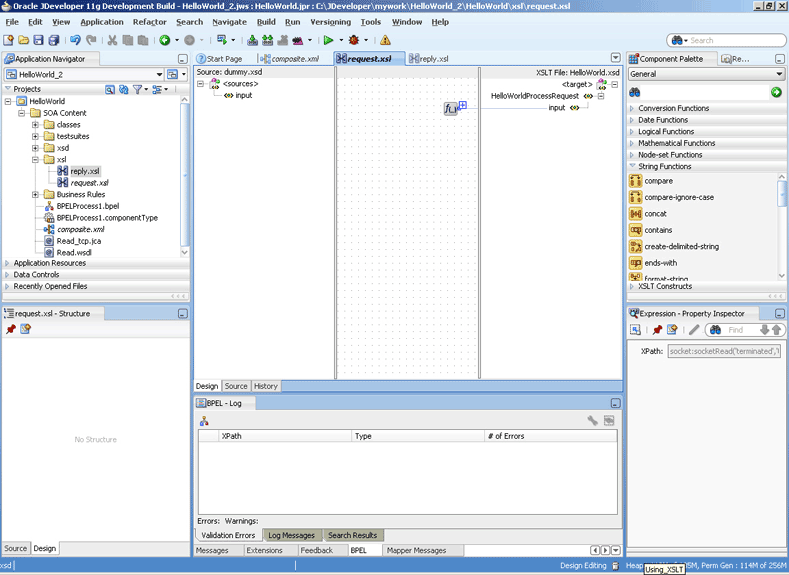
Link the
sockReadfunction in the middle pane to the targetinputnode on the right pane. The request.xsl (XSL mapper tool) with the XSL mapping is displayed, as shown in Figure 5-26.Figure 5-26 The JDeveloper - request.xsl Page
Description of "Figure 5-26 The JDeveloper - request.xsl Page"
-
-
Define the reply part of the inbound synchronous request/reply operation as follows:
-
From the Component Palette list, select Advanced, and then select Advanced Functions. A list of advanced functions are displayed.
-
In the reply.xsl page, drag and drop socketWrite from the Advanced Functions list of the Component Palette to the middle pane.
-
Double-click the socketWrite advanced function. The Edit Function - socketWrite dialog appears.
-
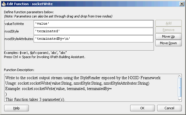
Enter the function parameters in the valueToWrite, nxsdStyle, and nxsdStyleAttributes fields, as shown in Figure 5-27.
Figure 5-27 The Edit Function - socketWrite Dialog
Description of "Figure 5-27 The Edit Function - socketWrite Dialog"
Note:
ThesocketWritefunction writes to the socket output stream by using theStyleReaderexposed by the NXSD framework. -
Click OK. The reply.xsl (XSL mapper tool) page is displayed.
-
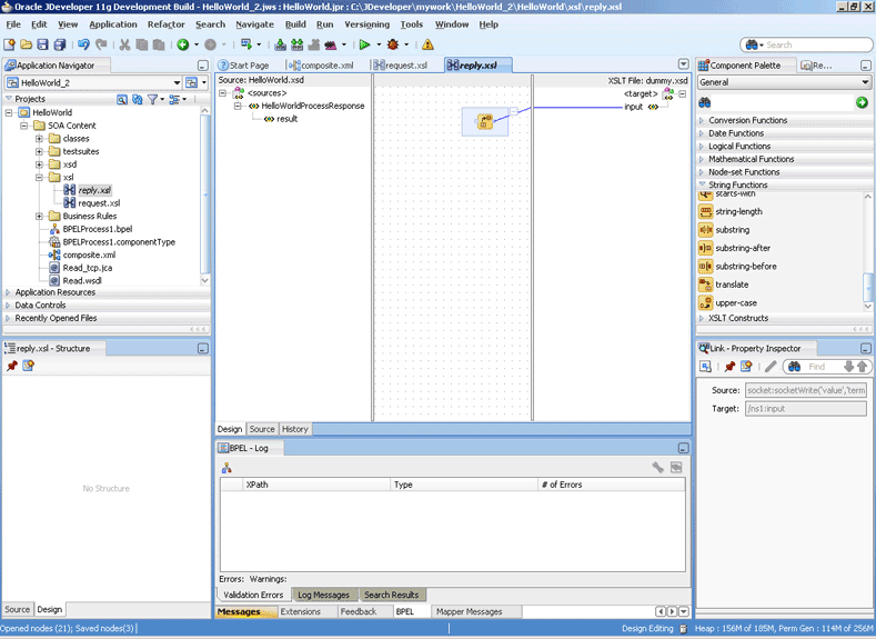
Link the
sockWritefunction in the middle pane to the targetinputnode on the right pane. The reply.xsl (XSL mapper tool) with the XSL mapping is displayed, as shown in Figure 5-28.Figure 5-28 The JDeveloper - reply.xsl Page
Description of "Figure 5-28 The JDeveloper - reply.xsl Page"
-
-
Click File, Save All. The request.xsl and reply.xsl files for the inbound Oracle Socket Adapter are created.
5.4.3.2 Designing XSL for Outbound Synchronous Request/Reply
This section describes the procedure for designing XSL for an outbound synchronous request/reply scenario by using the XSL mapper tool:
Note:
To perform this use case, you require the following files from theartifacts.zip file contained in the Adapters-101SocketAdapterHelloWorld sample:
-
artifacts/schemas/HellowWorld.xsd
You can access the Adapters-101SocketAdapterHelloWorld sample on the Oracle SOA Sample Code site.
Copy the HelloWorld.xsd file to HelloWorldComposite\xsd under the HelloWorldComposite project:
To design an SOA composite, perform the steps described in Section 5.5.1.2, "Designing the SOA Composite.".
Note:
The steps provided in Section 5.5.1.2, "Designing the SOA Composite" are applicable to a composite with Oracle BPEL PM. Alternatively, you can create a composite with Mediator.Create an Outbound Oracle Socket Adapter Reference
To create an outbound Oracle Socket Adapter reference, perform the following steps:
-
Drag and drop Socket Adapter from the Components Palette to the External References swim lane. The Welcome page of the Adapter Configuration Wizard is displayed.
-
Click Next. The Service Name page is displayed.
-
Enter the service name,
HelloWorldin the Service Name field and then click Next. The Adapter Interface page is displayed. -
Select Define from operation and schema (specified later), as shown in the Figure 5-16 and click Next. The Operation page is displayed.
-
Select Outbound Synchronous Request/Reply as the Operation Type and then click Next. The Socket Connection page is displayed.
-
Enter
eis/socket/OutboundSocketAdapterin the Socket Connection JNDI Name field and click Next. The Messages page is displayed. -
Click Browse For Schema File that appears at the end of the URL field in the Request Message Schema box. The Type Chooser dialog is displayed.
-
Click Project Schema Files, HelloWorld.xsd, and HelloWorldProcessRequest, as shown in Figure 5-18.
-
Click OK. The URL field in the Messages page is populated with the
HelloWorld.xsdfile. -
Click Browse For Schema File that appears at the end of the URL field in the Reply Message Schema box. The Type Chooser dialog is displayed.
-
Click Project Schema Files, HelloWorld.xsd, and HelloWorldProcessResponse.
-
Click OK. The URL fields in the Messages page are populated with the
HelloWorld.xsdfiles, as shown in Figure 5-19. -
Click Next. The Protocol page is displayed.
-
Select Use XSLT to define the handshake.
-
Click the create new xsl file icon that appears at the end of the Xslt field. The Input dialog appears.
-
Use the default value,
invoke.xsl, as the name of the XSL file and click OK. -
Click Finish. The invoke.xsl file appears in the XSL mapper tool, as shown in Figure 5-29.
Figure 5-29 The JDeveloper - invoke.xsl Page
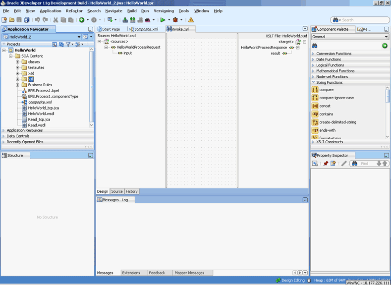
Description of "Figure 5-29 The JDeveloper - invoke.xsl Page"
-
Right-click the HelloWorldProcessResponse element on the target side. A menu is displayed, as shown in Figure 5-30.
Figure 5-30 The JDeveloper - invoke.xsl Page
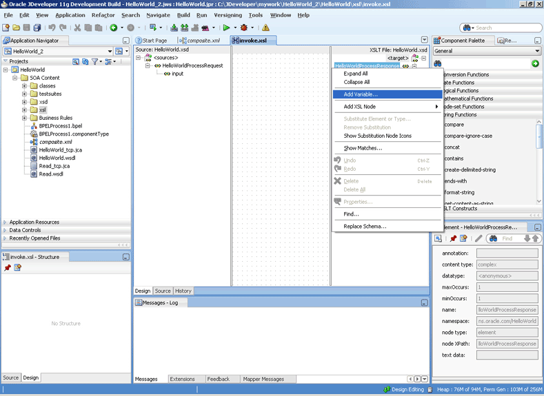
Description of "Figure 5-30 The JDeveloper - invoke.xsl Page"
-
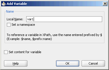
Click Add Variable.... The Add Variable dialog is displayed, as shown in Figure 5-31.
-
Enter
var1in the Local Name field, and click OK. The var1 variable is added to the target pane of the XSL mapper tool. -
From the Component Palette list, select Advanced; then, select Advanced Functions. A list of advanced functions is displayed.
-
Define the request part of the outbound synchronous request/reply operation, to write the data to the socket server, as follows:
-
Drag and drop socketWriteWithXlation from the Advanced Functions list of the Component Palette to the middle pane, as shown in Figure 5-32.
Figure 5-32 The JDeveloper - invoke.xsl Page
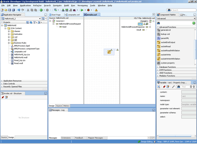
Description of "Figure 5-32 The JDeveloper - invoke.xsl Page"
-
Drag the var1 node to the socketWriteWithXlation function. A link is created, as shown in Figure 5-33.
Figure 5-33 The JDeveloper - invoke.xsl Page
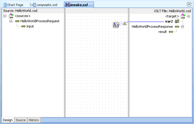
Description of "Figure 5-33 The JDeveloper - invoke.xsl Page"
-
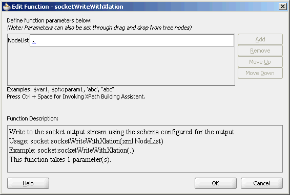
Double-click the socketWriteWithXlation advanced function. The Edit Function - socketWriteWithXlation dialog appears.
-
Enter a dot (.) in the NodeList field, as shown in Figure 5-34.
Figure 5-34 The Edit Function - socketWriteWithXlation Dialog
Description of "Figure 5-34 The Edit Function - socketWriteWithXlation Dialog"
Note:
ThesocketWriteWithXlationfunction writes to the socket output stream using the schema configured for the output.The dot (.) specified in the NodeList field signifies writing the HelloWorldProcessRequest to the top level node.
-
Click OK. A Warning dialog appears.
-
Click Yes. The invoke.xsl page is displayed. The request part of the Synchronous Request/Reply operation is defined.
-
-
Define the reply part of the outbound synchronous request/reply operation as follows:
-
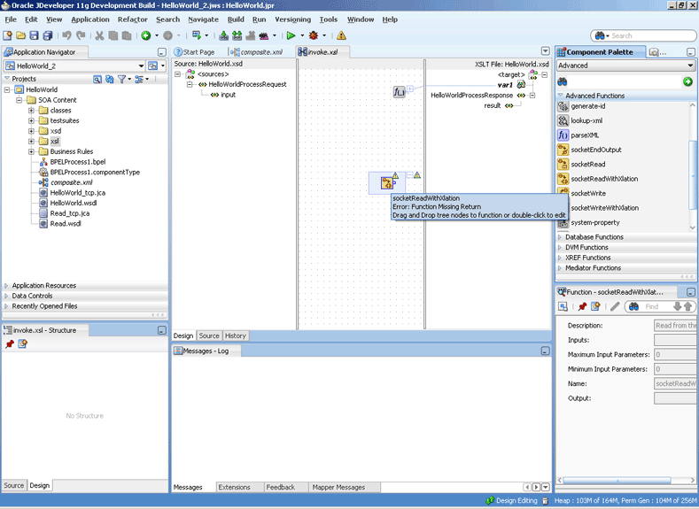
Drag and drop socketReadWithXlation from the Advanced Functions list of the Component Palette to the middle pane, as shown in Figure 5-35.
Figure 5-35 The JDeveloper - invoke.xsl Page
Description of "Figure 5-35 The JDeveloper - invoke.xsl Page"
-
From the Component Palette list, select General; then, select XSLT Constructs. A list of XSLT constructs is displayed.
-
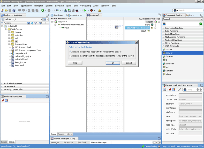
Drag copy-of from the Component Palette to HelloWorldProcessResponse in the target pane. The Copy-of Type Dialog appears, as shown in Figure 5-36.
Figure 5-36 The JDeveloper - invoke.xsl Page with Copy-of Type Dialog
Description of "Figure 5-36 The JDeveloper - invoke.xsl Page with Copy-of Type Dialog"
-
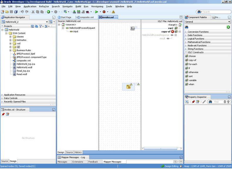
Click OK. The invoke.xsl (XSL mapper tool) page is displayed with the copy-of XSLT construct added to the target pane, as shown in Figure 5-37.
Figure 5-37 The JDeveloper - invoke.xsl Page
Description of "Figure 5-37 The JDeveloper - invoke.xsl Page"
-
Drag the copy-of XSLT construct to the socketReadWithXlation function. A link is created, as shown in Figure 5-38.
Figure 5-38 The JDeveloper - invoke.xsl Page
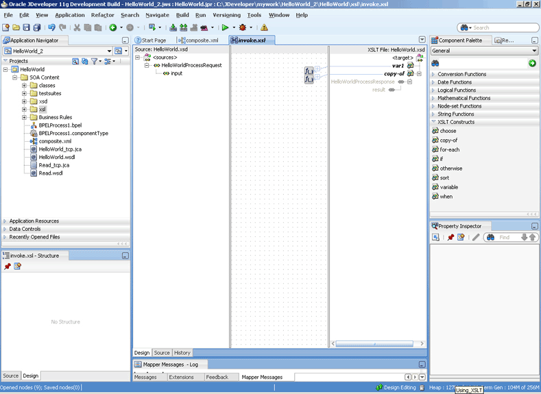
Description of "Figure 5-38 The JDeveloper - invoke.xsl Page"
-
-
Click File, Save All. The Outbound Synchronous Request/Reply handshake is defined.
5.4.4 Specifying a TCP Port in a Configuration Plan For an Oracle Socket Adapter
To specify a TCP port in a configuration plan for an Oracle Socket Adapter, perform the following steps (where <service-name> is Service name):
-
Add a port property to your <service-name>_tcp.jca file:
<property name="Port" value="Port"/>
-
Add the following code to your configuration plan XML file:
<service_name=<XXXXXX">
 <property>
  <property name="Port">
   <replace>2222</replace>
 </property>
 <binding type'"jca"/>
</service>
-
Add the port property to your .xml file under the service element and specify a default value, in this example, 1111
<service name="XXXXX" ui:wsdlLocation <interface.wsdl.interface="..."/> <binding.jca config="XXXX_tcp.jca"/> <property name="Port" type=xs:string" many="false" override="may">1111</property> </service> -
Deploy your composite with the configuration plan.
When deployed, the Oracle Socket Adapter listens on port 2222, as provided in the configuration plan.
If you deploy the composite without a configuration plan or if the configuration plan does not override the Port property, then the Oracle Socket Adapter listens on the socket that the composite.xml file's default Port property specifies (in this example, port 1111).
5.5 Oracle Socket Adapter Use Cases
This section includes the following Oracle Socket Adapter use cases:
5.5.1 Oracle Socket Adapter Hello World
This is a simple HelloWorld use case, which demonstrates the synchronous inbound request/response and synchronous outbound request/response modes of communication using Oracle Socket Adapter. The HelloWorld business process takes an input string from the Oracle Socket Adapter inbound service and publishes the message to the BPEL process. The BPEL process invokes the Oracle Socket Adapter outbound service (a simple HelloWorld Server, which adds a prefix?Hello? to the input string and returns it) and returns the received string using a synchronous reply.
This use case includes the following sections:
-
Section 5.5.1.3, "Creating the Inbound Oracle Socket Adapter Service"
-
Section 5.5.1.4, "Creating the Outbound Oracle Socket Adapter Service"
5.5.1.1 Prerequisites
To perform this use case, you require the following files from the artifacts.zip file contained in the Adapters-101SocketAdapterHelloWorld sample:
-
artifacts/schemas/HelloWorld.xsd -
artifacts/xsl/request.xsl -
artifacts/xsl/reply.xsl -
artifacts/xsl/invoke.xsl
You can access the Adapters-101SocketAdapterHelloWorld sample on the Oracle SOA Sample Code site.
5.5.1.2 Designing the SOA Composite
You must create a JDeveloper application to contain the SOA composite. To create an application and a project for the use case, perform the following:
-
In Application Navigator of JDeveloper, click New Application. The Create Generic Application - Name your application page is displayed.
-
Enter
helloworld-socketin the Application Name field, as shown in Figure 5-39, and then click Next. The Name your project page is displayed.Figure 5-39 The Create SOA Application Dialog
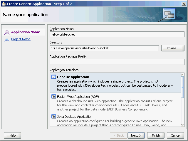
Description of "Figure 5-39 The Create SOA Application Dialog"
-
Click OK. The Name Your Project dialog is displayed.
-
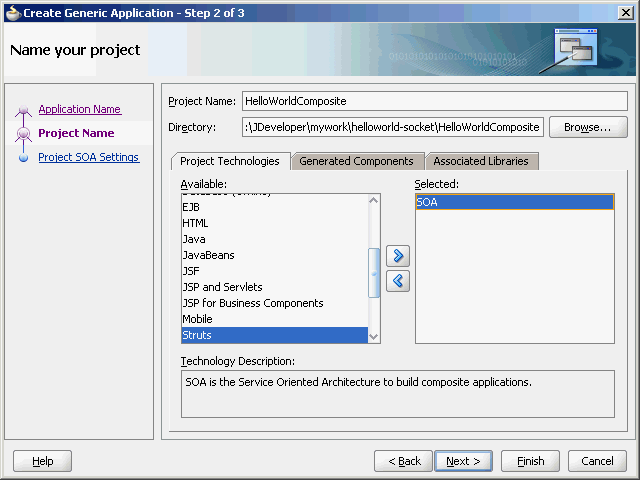
Enter
HelloWorldCompositein the Project Name field, and then select SOA under Project Technologies and move it to the Selected box by clicking the right-arrow, as shown in Figure 5-40.The HelloWorld application and the HelloWorldComposite project appear in the Application Navigator.
-
Click Next. The Configure SOA settings dialog appears.
-
Select Composite With BPEL in the Composite Template box, as shown in Figure 5-41, and click Finish. The Create BPEL Process dialog is displayed.
Figure 5-41 The Configure SOA Settings Dialog
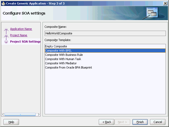
Description of "Figure 5-41 The Configure SOA Settings Dialog"
-
Enter
HelloWorldFlowin the Name field and select Define Service Later from the Template box, as shown in Figure 5-42.Figure 5-42 The Create BPEL Process Dialog
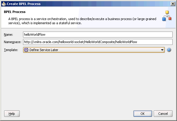
Description of "Figure 5-42 The Create BPEL Process Dialog"
-
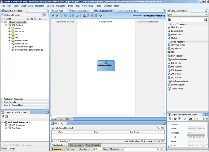
Click OK. The HelloWorld application and the HelloWorldComposite project appear in the design area, as shown in Figure 5-43.
Figure 5-43 The JDeveloper - composite.xml
Description of "Figure 5-43 The JDeveloper - composite.xml"
-
Copy the
HelloWorld.xsdfile to the xsd directory in your project (see Section 5.5.1.1, "Prerequisites" for the location of this file). -
Copy the
request.xsl,reply.xsl, andinvoke.xslfiles to the xsl directory in your project (see Section 5.5.1.1, "Prerequisites" for the location of these files).
5.5.1.3 Creating the Inbound Oracle Socket Adapter Service
Perform the following steps to create an inbound Oracle Socket Adapter service:
-
Drag and drop Socket Adapter from the Components Palette to the Exposed Services swim lane. The Welcome page of the Adapter Configuration Wizard is displayed.
-
Click Next. The Service Name page is displayed.
-
Enter
HelloWorldClientin the Service Name field, as shown in Figure 5-44.Figure 5-44 The Adapter Configuration Wizard Service Name Page

Description of "Figure 5-44 The Adapter Configuration Wizard Service Name Page"
-
Click Next. The Adapter Interface page is displayed.
-
Select Define from operation and schema (specified later), as shown in the Figure 5-45 and click Next. The Operation page is displayed.
Figure 5-45 The Adapter Configuration Wizard - Adapter Interface Page

Description of "Figure 5-45 The Adapter Configuration Wizard - Adapter Interface Page"
-
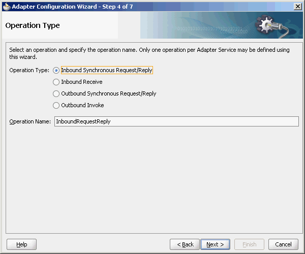
Select Inbound Synchronous Request/Reply as the Operation Type, as shown in Figure 5-46.
Figure 5-46 The Adapter Configuration Wizard Operation Page
Description of "Figure 5-46 The Adapter Configuration Wizard Operation Page"
-
Click Next. The Socket Connection page is displayed.
-
Enter
eis/socket/InboundSocketAdapterin the Socket Connection JNDI Name field, as shown in Figure 5-47, and click Next. The Messages page is displayed.Figure 5-47 The Adapter Configuration Wizard Socket Connection Page

Description of "Figure 5-47 The Adapter Configuration Wizard Socket Connection Page"
-
Click Browse For Schema File that appears at the end of the URL field in the Request Message Schema box. The Type Chooser dialog is displayed.
-
Click Project Schema Files, HelloWorld.xsd, and HelloWorldProcessRequest, as shown in Figure 5-48.
-
Click OK. The URL field in the Messages page is populated with the
HelloWorld.xsdfile. -
Click Browse For Schema File that appears at the end of the URL field in the Reply Message Schema box. The Type Chooser dialog is displayed.
-
Click Project Schema Files, HelloWorld.xsd, and HelloWorldProcessRequest.
-
Click OK. The URL fields in the Messages page are populated with the
HelloWorld.xsdfiles, as shown in Figure 5-49.Figure 5-49 The Adapter Configuration Wizard File Messages Page

Description of "Figure 5-49 The Adapter Configuration Wizard File Messages Page"
-
Click Next. The Protocol page is displayed.
-
Select Use XSLT to define the handshake.
-
Click Browse to select the XSL file that appears at the end of the Xslt field. The SOA Resource Browser dialog is displayed.
-
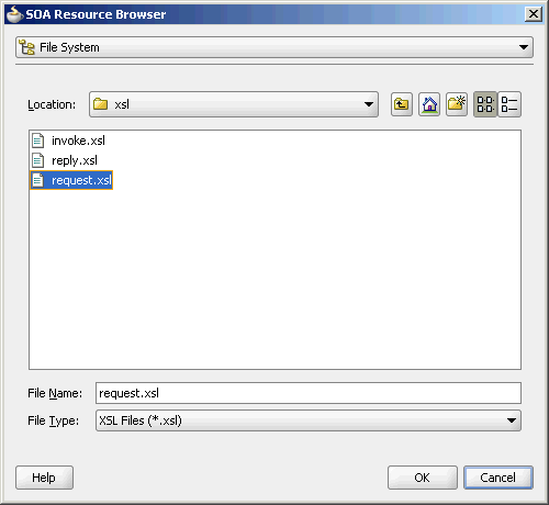
Select request.xsl as the file name, as shown in Figure 5-50, and click OK. The Xslt field is populated.
Figure 5-50 The SOA Resource Browser Dialog
Description of "Figure 5-50 The SOA Resource Browser Dialog"
-
Click Browse to select the XSL file that appears at the end of the ReplyXslt field. The SOA Resource Browser dialog is displayed.
-
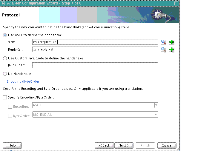
Select reply.xsl as the file name and click OK. The Xslt field is populated, as shown in Figure 5-51.
Figure 5-51 The Adapter Configuration Wizard Protocol Page
Description of "Figure 5-51 The Adapter Configuration Wizard Protocol Page"
-
Click Finish. The composite.xml page appears, as shown in Figure 5-52.
Figure 5-52 The JDeveloper - composite.xml Page
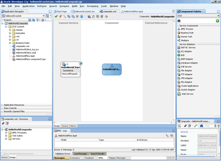
Description of "Figure 5-52 The JDeveloper - composite.xml Page"
5.5.1.4 Creating the Outbound Oracle Socket Adapter Service
Perform the following steps to create an outbound Oracle Socket Adapter service:
-
Drag and drop Socket Adapter from the Component Palette to the External References swim lane. The Welcome page of the Adapter Configuration Wizard is displayed.
-
Click Next. The Service Name page is displayed.
-
Enter
HelloWorldServerin the Service Name field. -
Click Next. The Adapter Interface page is displayed.
-
Select Define from operation and schema (specified later), and click Next. The Operation page is displayed.
-
Select Outbound Synchronous Request/Reply as the operation type, as shown in Figure 5-53.
Figure 5-53 The Adapter Configuration Wizard Operation Type Page
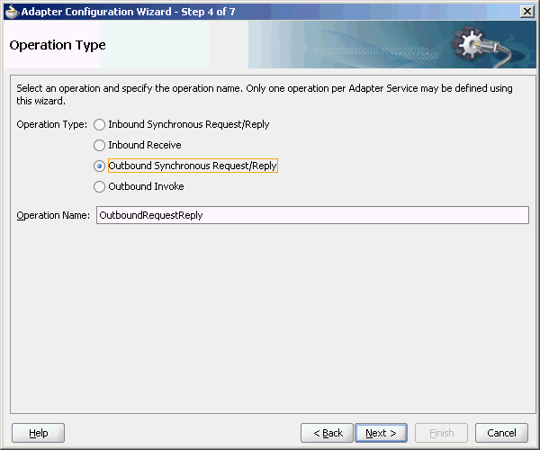
Description of "Figure 5-53 The Adapter Configuration Wizard Operation Type Page"
-
Click Next. The Socket Connection page is displayed.
-
Enter
eis/socket/OutboundSocketAdapterin the Socket Connection JNDI Name field, as shown in Figure 5-54, and click Next. The Messages page is displayed.Figure 5-54 The Adapter Configuration Wizard Socket Connection Page
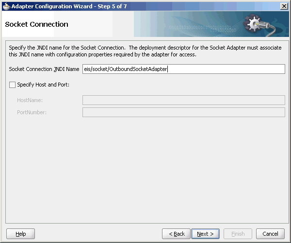
Description of "Figure 5-54 The Adapter Configuration Wizard Socket Connection Page"
-
Click Browse For Schema File that appears at the end of the URL field in the Request Message Schema box. The Type Chooser dialog is displayed.
-
Click Project Schema Files, HelloWorld.xsd, and HelloWorldProcessRequest, as shown in Figure 5-48.
-
Click OK. The URL field in the Messages page is populated with the
HelloWorld.xsdfile. -
Click Browse For Schema File that appears at the end of the URL field in the Reply Message Schema box. The Type Chooser dialog is displayed.
-
Click Project Schema Files, HelloWorld.xsd, and HelloWorldProcessResponse.
-
Click OK. The URL fields in the Messages page are populated with the
HelloWorld.xsdfiles, as shown in Figure 5-49. -
Click Next. The Protocol page is displayed.
-
Select Use XSLT to define the handshake.
-
Click Browse to select the XSL file that appears at the end of the Xslt field. The SOA Resource Browser dialog is displayed.
-
Select invoke.xsl as the file name, as shown in Figure 5-55, and click OK. The Xslt field is populated.
Figure 5-55 The SOA Resource Browser Dialog
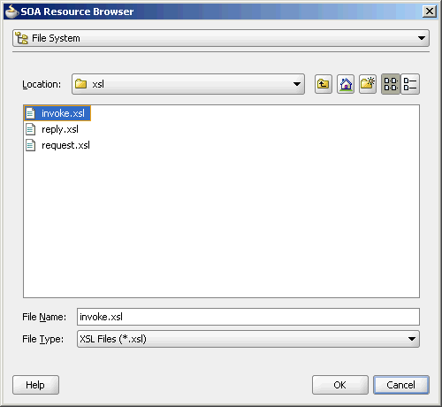
Description of "Figure 5-55 The SOA Resource Browser Dialog"
-
Click Finish. The Composite.xml page appears, as shown in Figure 5-56.
Figure 5-56 The JDeveloper - composite.xml Page
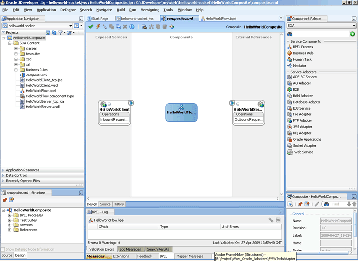
Description of "Figure 5-56 The JDeveloper - composite.xml Page"
5.5.1.5 Wiring Services and Activities
You have to assemble or wire the three components that you have created: Inbound adapter service, BPEL process, Outbound adapter reference. Perform the following steps to wire the components:
-
Drag the small triangle in the HelloWorldClient in the Exposed Services area to the drop zone that appears as a green triangle in the HelloWorldFlow BPEL process in the Components area.
-
Drag the small triangle in the HelloWorldFlow BPEL process in the Components area to the drop zone that appears as a green triangle in the HelloWorldServer in the External References area.
The JDeveloper composite.xml appears, as shown in Figure 5-57.
Figure 5-57 The JDeveloper - composite.xml
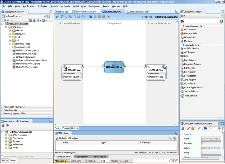
Description of "Figure 5-57 The JDeveloper - composite.xml"
-
Click File, Save All.
-
Double-click HelloWorldFlow. The BPELHelloWorld.bpel page is displayed.
-
Drag and drop a Receive activity from the Component Palette to the design area, as shown in Figure 5-58.
Figure 5-58 The JDeveloper - HelloWorldFlow.bpel
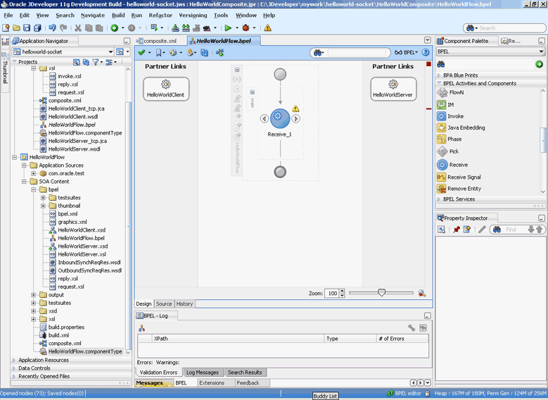
Description of "Figure 5-58 The JDeveloper - HelloWorldFlow.bpel"
-
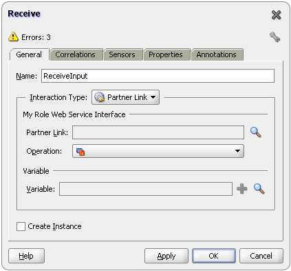
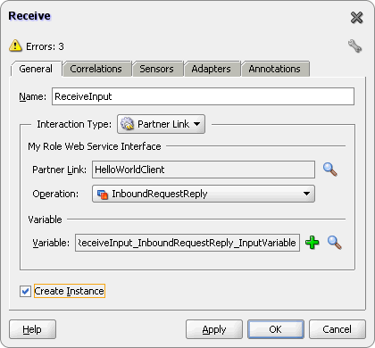
Double-click the Receive activity. The Receive dialog is displayed.
-
Enter
ReceiveInputin the Name field, as shown in Figure 5-59. -
Click Browse Partner Links at the end of the Partner Link field. The Partner Link Chooser dialog is displayed.
-
Select HelloWorldClient, as shown in Figure 5-60, and click OK.
Figure 5-60 The Partner Link Chooser Dialog
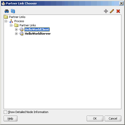
Description of "Figure 5-60 The Partner Link Chooser Dialog"
-
Click the Auto-Create Variable icon to the right of the Variable field in the Receive dialog, as shown in Figure 5-61. The Create Variable dialog is displayed.
-
Select the default variable name and click OK. The Variable field is populated with the default variable name.
-
Check Create Instance, and click OK. The JDeveloper HelloWorldFlow.bpel page appears, as shown in Figure 5-62.
Figure 5-62 The JDeveloper - HelloWorldFlow.bpel
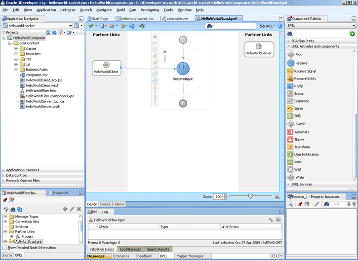
Description of "Figure 5-62 The JDeveloper - HelloWorldFlow.bpel"
-
Drag and drop an Invoke activity after the ReceiveInput activity from the Component Palette to the design area, as shown in Figure 5-63.
Figure 5-63 The JDeveloper - HelloWorldFlow.bpel
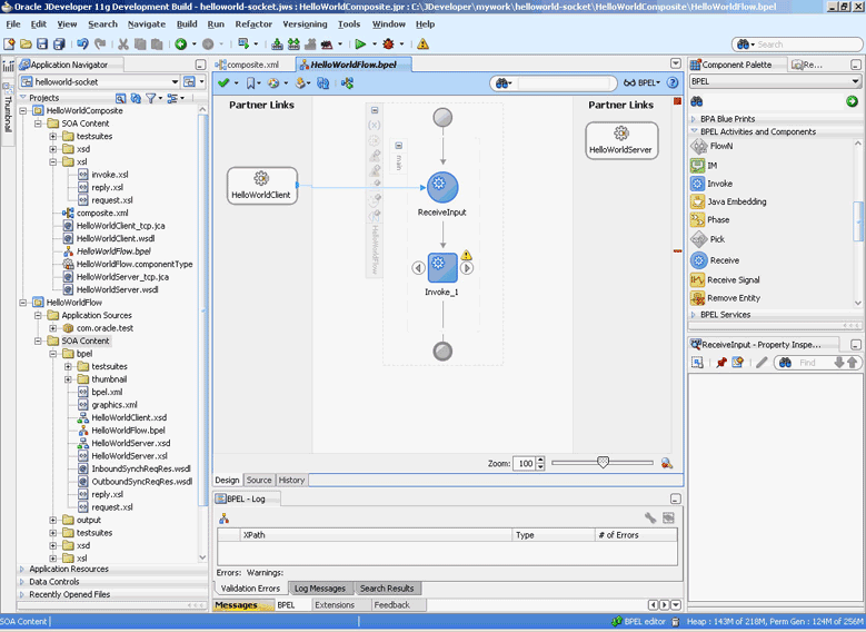
Description of "Figure 5-63 The JDeveloper - HelloWorldFlow.bpel"
-
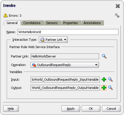
Double-click the Invoke activity. The Invoke dialog is displayed.
-
Enter
WriteHelloWorldin the Name field, as shown in Figure 5-64.Figure 5-64 The JDeveloper - HelloWorldFlow.bpel
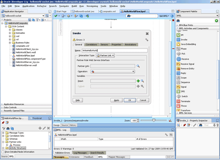
Description of "Figure 5-64 The JDeveloper - HelloWorldFlow.bpel"
-
Click Browse Partner Links at the end of the Partner Link field. The Partner Link Chooser dialog is displayed.
-
Select HelloWorldServer, as shown in Figure 5-65, and click OK.
Figure 5-65 The Partner Link Chooser Dialog
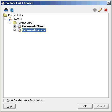
Description of "Figure 5-65 The Partner Link Chooser Dialog"
-
Click the Automatically Create Input Variable icon to the right of the Input variable field in the Invoke dialog. The Create Variable dialog is displayed.
-
Select the default variable name and click OK. The Variable field is populated with the default variable name.
-
Repeat the same for selecting the output variable. The Invoke dialog is displayed, as shown in Figure 5-66.
-
Click OK. The JDeveloper HelloWorldFlow.bpel page appears, as shown in Figure 5-67.
Figure 5-67 The JDeveloper - HelloWorldFlow.bpel
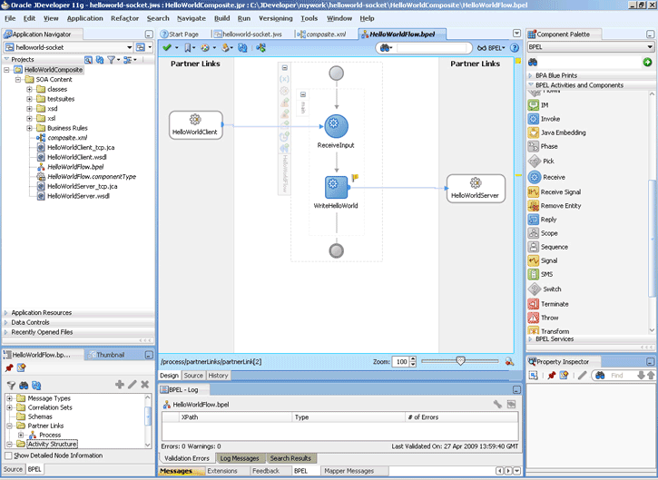
Description of "Figure 5-67 The JDeveloper - HelloWorldFlow.bpel"
-
Drag and drop a Reply activity from the Component Palette to the design area, as shown in Figure 5-68.
Figure 5-68 The JDeveloper - HelloWorldFlow.bpel
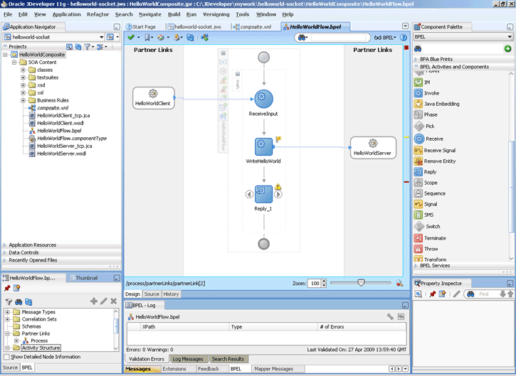
Description of "Figure 5-68 The JDeveloper - HelloWorldFlow.bpel"
-
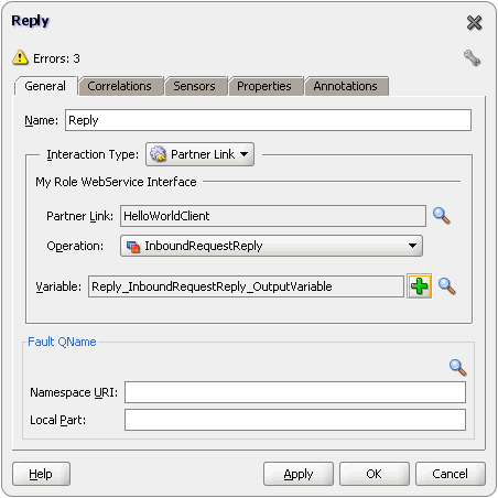
Double-click the Reply activity. The Reply dialog is displayed.
-
Enter
Replyin the Name field. -
Click Browse Partner Links at the end of the Partner Link field. The Partner Link Chooser dialog is displayed.
-
Select HelloWorldClient, as shown in Figure 5-60, and click OK.
-
Click the Auto-Create Variable icon to the right of the Variable field in the Reply dialog. The Create Variable dialog is displayed.
-
Select the default variable name and click OK. The Variable field is populated with the default variable name, as shown in Figure 5-69.
-
Click OK. The JDeveloper HelloWorldFlow.bpel page appears, as shown in Figure 5-70.
Figure 5-70 The JDeveloper - HelloWorldFlow.bpel
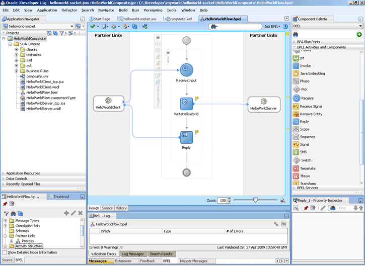
Description of "Figure 5-70 The JDeveloper - HelloWorldFlow.bpel"
-
Drag and drop an Assign activity from the Component Palette in between the Receive and Invoke activities in the design area.
-
Double-click the Assign activity. The Assign dialog is displayed.
-
Click the Copy Operation tab. The Assign dialog is displayed, as shown in Figure 5-71.
Figure 5-71 The Assign Dialog - Copy Operation Tab
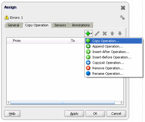
Description of "Figure 5-71 The Assign Dialog - Copy Operation Tab"
-
Select Copy Operation. The Create Copy Operation dialog is displayed.
-
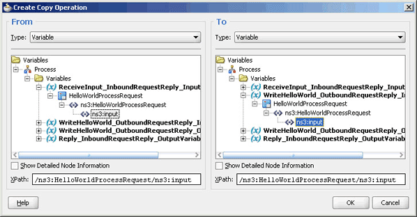
In the left pane, under the ReceiveInput_InboundRequestReply_InputVariable variable select, ns3:input.
-
In the right pane, under the WriteHelloWorld_OutboundRequestReply_InputVariable variable select, ns3:input, as shown in Figure 5-72.
Figure 5-72 The Create Copy Operation Dialog
Description of "Figure 5-72 The Create Copy Operation Dialog"
-
Click OK. The Assign dialog is displayed.
-
Click OK. The JDeveloper HelloWorldFlow.bpel page is displayed.
-
Add another Assign activity in between the Invoke and the Reply activities.
-
Double-click the assign activity.
-
Click the Copy Operation tab, and select Copy Operation.
-
In the left pane, select ns3:result under WriteHelloWorld_OutboundRequestReply_OutputVariable.
-
In the right pane, select ns3:result under Reply_InboundRequestReply_OutputVariable and click OK.
-
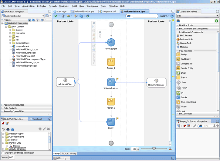
Click OK, the JDeveloper HelloWorldFlow.bpel page is displayed, as shown in Figure 5-73.
Figure 5-73 The JDeveloper - HelloWorldFlow.bpel
Description of "Figure 5-73 The JDeveloper - HelloWorldFlow.bpel"
-
Click File, Save All.
5.5.1.6 Deploying with JDeveloper
You must deploy the application profile for the SOA project and the application you created in the preceding steps. To deploy the application profile using JDeveloper, perform the following steps:
-
Create an application server connection. For more information, see Section 2.6, "Creating an Application Server Connection for Oracle JCA Adapters."
-
Deploy the application. For more information, see Section 2.7, "Deploying Oracle JCA Adapter Applications from JDeveloper."
5.5.1.7 Monitoring Using the Oracle Enterprise Manager Fusion Middleware Control Console (Fusion Middleware Control Console)
You can monitor the deployed SOA composite using the Fusion Middleware Control Console. Perform the following steps:
-
Navigate to
http://servername:portnumber/em. The composite you deployed appears in the application navigator. -
Click the SOA composite that you deployed. The Dashboard is displayed.
Note your Instance ID in the Recent Instances area.
-
Click the Instances tab. The Instance IDs of the SOA composite are listed.
-
Click the Instance ID that you noted in Step 2. The Flow Trace page is displayed.
-
Click your BPEL process instance. The Audit Trail of the BPEL process instance is displayed.
-
Expand a payload node to view payload details.
-
Click the Flow tab to view the process flow. Additionally, click an activity (such as invoke, receive) to view the details of an activity.
5.5.2 Flight Information Display System
The flight information display system use case demonstrates the various modes of defining handshakes by using Oracle Socket Adapter.A flight information display server (FIDS) is started by an FIDS client requesting information on flight status for flights originating from a particular source, JFK, or SFO. The FIDS, in turn, invokes flight data requests for three airlines, Airline1, Airline 2, and Airline 3. The FIDS then collates the information received and replies to the FIDS client by using the HTTP protocol.
This use case includes the following sections:
-
Section 5.5.2.3, "Creating the Inbound Oracle Socket Adapter Service"
-
Section 5.5.2.4, "Creating Outbound Oracle Socket Adapter Services"
-
Section 5.5.2.7, "Monitoring Using the Fusion Middleware Control Console"
5.5.2.1 Prerequisites
To perform this use case, you require the following files from the artifacts.zip file contained in the Adapters-102SocketAdapterFlightInformationDisplaySystem sample:
-
artifacts/schemas/Airline1.xsd -
artifacts/schemas/Airline2.xsd -
artifacts/schemas/Airline3.xsd -
artifacts/schemas/FIDS.xsd -
artifacts/xsl/request.xsl -
artifacts/xsl/reply.xsl -
artifacts/xsl/invoke.xsl
To obtain the Adapters-102SocketAdapterFlightInformationDisplaySystem sample, access the Oracle SOA Sample Code site.
5.5.2.2 Designing the SOA Composite
You must create a JDeveloper application to contain the SOA composite. To create an application and a project for the use case, perform the following steps:
-
In the Application Navigator of JDeveloper, click New Application. The Create Generic Application - Name your application page is displayed.
-
Enter
FIDSAppin the Application Name field, and then click Next. The Name your project page is displayed. -
Click OK. The Name Your Project dialog is displayed.
-
Enter
FIDSCompositein the Project Name field, and then select SOA under Project Technologies and move it to the Selected box by clicking the right-arrow.The FIDSApp application and the FIDSComposite project appear in the Application Navigator.
-
Click Next. The Configure SOA Settings dialog appears.
-
Select Composite With BPEL in the Composite Template box, and click Finish. The Create BPEL Process dialog is displayed.
-
Enter
BPEL_FIDSin the Name field and select Define Service Later from the Template box. -
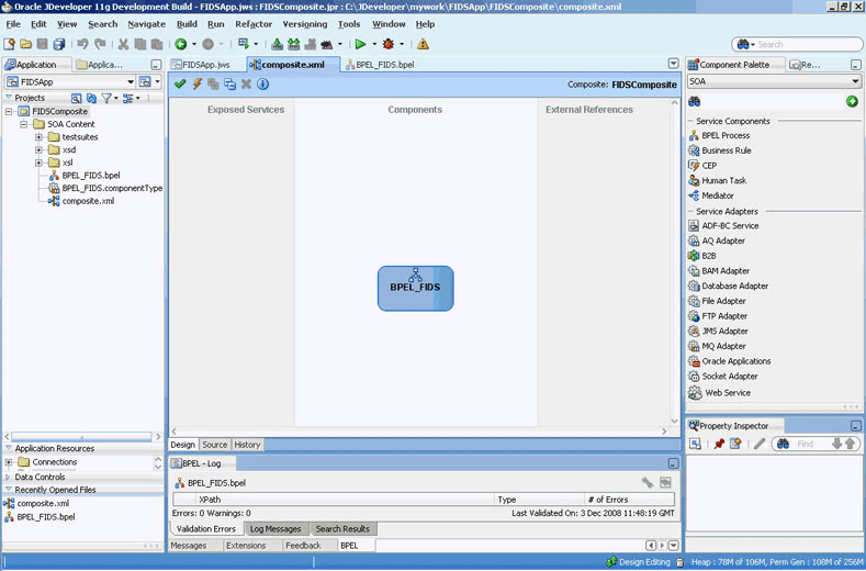
Click OK. The FIDSApp application and the FIDSComposite project appear in the design area, as shown in Figure 5-74.
Figure 5-74 The JDeveloper - composite.xml
Description of "Figure 5-74 The JDeveloper - composite.xml"
-
Copy the
Airline1.xsd,Airline2.xsd,Airline3.xsd, andFIDS.xsdfiles toFIDSComposite\xsdunder the projectFIDSComposite(see Section 5.5.2.1, "Prerequisites" for the location of these files). -
Copy
invoke.xsl,request.xsl, andreply.xsltoFIDSComposite\xslunder the projectFIDSComposite(see Section 5.5.2.1, "Prerequisites" for the location of these files).
5.5.2.3 Creating the Inbound Oracle Socket Adapter Service
Perform the following steps to create an inbound Oracle Socket Adapter service that would be used to expose the FIDSApp application:
-
Drag and drop Socket Adapter from the Components Palette to the Exposed Services swim lane. The Welcome page of the Adapter Configuration Wizard is displayed.
-
Click Next. The Service Name page is displayed.
-
Enter
FIDSin the Service Name field. -
Click Next. The Adapter Interface page is displayed.
-
Select Define from operation and schema (specified later), and click Next. The Operation page is displayed.
-
Select Inbound Synchronous Request/Reply as the operation type.
-
Click Next. The Socket Connection page is displayed.
-
Enter
eis/socket/InboundSocketAdapterin the Socket Connection JNDI Name field and then select Specify Host and Port, as shown in Figure 5-75.Figure 5-75 The Adapter Configuration Wizard Socket Connection Page
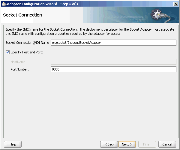
Description of "Figure 5-75 The Adapter Configuration Wizard Socket Connection Page"
-
Enter
9000in the PortNumber field and click Next. The Messages page is displayed. -
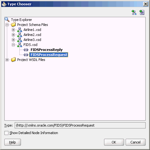
Click Browse For Schema File that appears at the end of the URL field in the Request Message Schema box. The Type Chooser dialog is displayed.
-
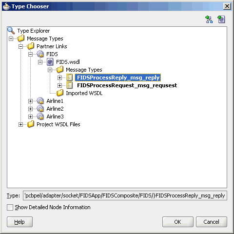
Click Project Schema Files, FIDS.xsd, and FIDSProcessRequest, as shown in Figure 5-76.
-
Click OK. The URL field in the Messages page is populated with the FIDS.xsd file.
-
Click Browse For Schema File that appears at the end of the URL field in the Reply Message Schema box. The Type Chooser dialog is displayed.
-
Click Project Schema Files, FIDS.xsd, and FIDSProcessReply.
-
Click OK. The URL fields in the Messages page are populated with the FIDS.xsd files, as shown in Figure 5-77.
Figure 5-77 The Adapter Configuration Wizard - Messages Page
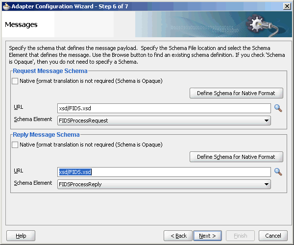
Description of "Figure 5-77 The Adapter Configuration Wizard - Messages Page"
-
Click Next. The Protocol page is displayed.
-
Select Use XSLT to define the handshake.
-
Click the Browse to select the XSL file icon that appears at the end of the Xslt field. The SOA Resource Browser dialog is displayed.
-
Select request.xsl as the file name and click OK. The Xslt field is populated.
-
Click the Browse to select the XSL file icon that appears at the end of the ReplyXslt field. The SOA Resource Browser dialog is displayed.
-
Select reply.xsl as the file name and click OK. The Xslt field is populated, as shown in Figure 5-78.
Figure 5-78 The Adapter Configuration Wizard - Protocol Page
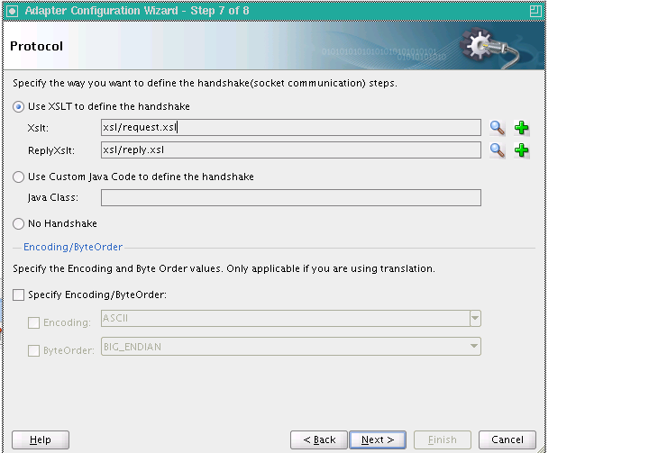
Description of "Figure 5-78 The Adapter Configuration Wizard - Protocol Page"
-
Click Finish. The composite.xml page appears, as shown in Figure 5-79.
Figure 5-79 The JDeveloper - composite.xml Page
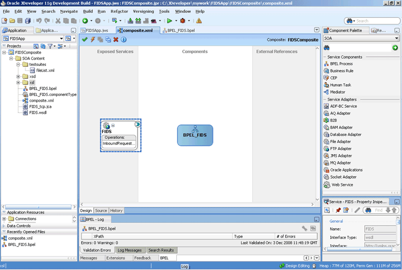
Description of "Figure 5-79 The JDeveloper - composite.xml Page"
5.5.2.4 Creating Outbound Oracle Socket Adapter Services
Perform the following steps to create an outbound Oracle Socket Adapter service for the Airline1 server socket:
-
Drag and drop Socket Adapter from the Component Palette to the External References swim lane. The Welcome page of the Adapter Configuration Wizard is displayed.
-
Click Next. The Service Name page is displayed.
-
Enter
Airline1in the Service Name field. -
Click Next. The Adapter Interface page is displayed.
-
Select Define from operation and schema (specified later), and click Next. The Operation page is displayed.
-
Select Outbound Synchronous Request/Reply as the Operation Type.
-
Click Next. The Socket Connection page is displayed.
-
Enter
eis/socket/OutboundSocketAdapterin the Socket Connection JNDI Name field, as shown in Figure 5-80, and then select Specify Host and Port.Figure 5-80 The Adapter Configuration Wizard - Socket Connection Page

Description of "Figure 5-80 The Adapter Configuration Wizard - Socket Connection Page"
-
Enter the name of the system where the Airline1 socket server program must run in the HostName field and
9001in the PortNumber field, and click Next. The Messages page is displayed. -
Click Browse For Schema File that appears at the end of the URL field in the Request Message Schema box. The Type Chooser dialog is displayed.
-
Click Project Schema Files, Airline1.xsd, and Source.
-
Click OK. The URL field in the Messages page is populated with the Airline1.xsd file.
-
Click Browse For Schema File that appears at the end of the URL field in the Reply Message Schema box. The Type Chooser dialog is displayed.
-
Click Project Schema Files, Airline1.xsd, and Flight-Details.
-
Click OK. The URL fields in the Messages page are populated with the
Airline1.xsdfiles, as shown in Figure 5-81.Figure 5-81 The Adapter Configuration Wizard - Messages Page
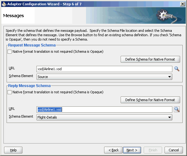
Description of "Figure 5-81 The Adapter Configuration Wizard - Messages Page"
-
Click Next. The Protocol page is displayed.
-
Select Use XSLT to define the handshake.
-
Click Browse to select the XSL file that appears at the end of the Xslt field. The SOA Resource Browser dialog is displayed.
-
Select invoke.xsl as the file name, as shown in Figure 5-82, and click OK. The Xslt field is populated.
Figure 5-82 The SOA Resource Browser Dialog

Description of "Figure 5-82 The SOA Resource Browser Dialog"
-
Click Finish. The composite.xml page appears, as shown in Figure 5-83.
Figure 5-83 The JDeveloper - composite.xml Page
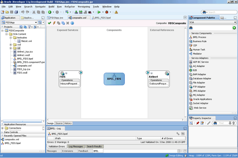
Description of "Figure 5-83 The JDeveloper - composite.xml Page"
Perform the following steps to create an outbound Oracle Socket Adapter service for the Airline2 server socket:
-
Drag and drop Socket Adapter from the Component Palette to the External References swim lane. The Welcome page of the Adapter Configuration Wizard is displayed.
-
Click Next. The Service Name page is displayed.
-
Enter
Airline2in the Service Name field. -
Click Next. The Adapter Interface page is displayed.
-
Select Define from operation and schema (specified later), and click Next. The Operation page is displayed.
-
Select Outbound Synchronous Request/Reply as the operation type.
-
Click Next. The Socket Connection page is displayed.
-
Enter
eis/socket/OutboundSocketAdapterin the Socket Connection JNDI Name field and then select Specify Host and Port. -
Enter the name of the system where the Airline2 socket server program must run in the HostName field and
9002in the PortNumber field, and click Next. The Messages page is displayed. -
Click Browse For Schema File that appears at the end of the URL field in the Request Message Schema box. The Type Chooser dialog is displayed.
-
Click Project Schema Files, Airline2.xsd, and Source.
-
Click OK. The URL field in the Messages page is populated with the
Airline2.xsdfile. -
Click Browse For Schema File that appears at the end of the URL field in the Reply Message Schema box. The Type Chooser dialog is displayed.
-
Click Project Schema Files, Airline2.xsd, and flight-details.
-
Click OK. The URL fields in the Messages page are populated with the
Airline2.xsdfiles. -
Click Next. The Protocol page is displayed.
-
Select No Handshake.
-
Click Finish. The composite.xml page appears, as shown in Figure 5-84.
Figure 5-84 The JDeveloper - composite.xml Page
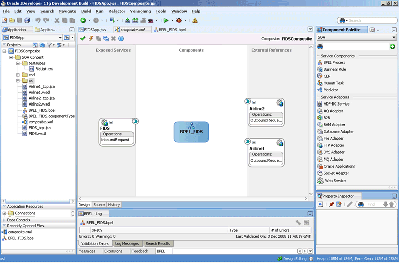
Description of "Figure 5-84 The JDeveloper - composite.xml Page"
Perform the following steps to create an outbound Oracle Socket Adapter service for the Airline3 server socket:
-
Drag and drop Socket Adapter from the Component Palette to the External References swim lane. The Welcome page of the Adapter Configuration Wizard is displayed.
-
Click Next. The Service Name page is displayed.
-
Enter
Airline3in the Service Name field. -
Click Next. The Adapter Interface page is displayed.
-
Select Define from operation and schema (specified later), and click Next. The Operation page is displayed.
-
Select Outbound Synchronous Request/Reply as the operation type.
-
Click Next. The Socket Connection page is displayed.
-
Enter
eis/socket/OutboundSocketAdapterin the Socket Connection JNDI Name field and then select Specify Host and Port. -
Enter the name of the system where the Airline3 socket server program must run in the HostName field and
9003in the PortNumber field, and click Next. The Messages page is displayed. -
Click Browse For Schema File that appears at the end of the URL field in the Request Message Schema box. The Type Chooser dialog is displayed.
-
Click Project Schema Files, Airline3.xsd, and src.
-
Click OK. The URL field in the Messages page is populated with the
Airline3.xsdfile. -
Click Browse For Schema File that appears at the end of the URL field in the Reply Message Schema box. The Type Chooser dialog is displayed.
-
Click Project Schema Files, Airline3.xsd, and airline.
-
Click OK. The URL fields in the Messages page are populated with the
Airline3.xsdfiles. -
Click Next. The Protocol page is displayed.
-
Select Use Custom Java Code to define the handshake.
-
Enter
com.oracle.socket.fids.custom.Airline3Customin the Java Class field. -
Click Finish. The composite.xml page appears, as shown in Figure 5-85.
Figure 5-85 The JDeveloper - composite.xml Page
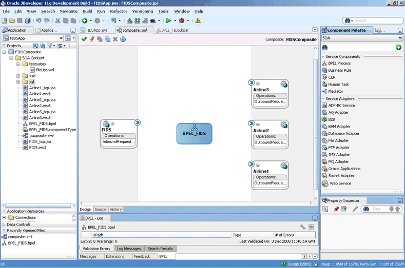
Description of "Figure 5-85 The JDeveloper - composite.xml Page"
5.5.2.5 Wiring Services and Activities
You have to assemble or wire the components that you have created: Inbound adapter service, BPEL process, Outbound adapter references. Perform the following steps to wire the components:
-
Drag the small triangle in the FIDS client in the Exposed Services area to the drop zone that appears as a green triangle in the BPEL_FIDS process in the Components area.
-
Drag the small triangle in the BPEL_FIDS process in the Components area to the drop zone that appears as a green triangle in the Airline1, Airline2, and Airline3 servers in the External References area.
The JDeveloper composite.xml file appears, as shown in Figure 5-86.
Figure 5-86 The JDeveloper - composite.xml
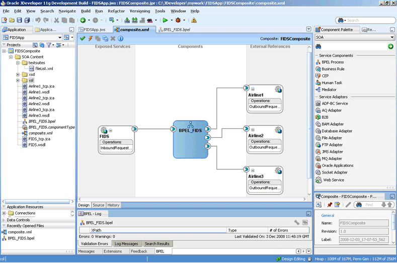
Description of "Figure 5-86 The JDeveloper - composite.xml"
-
Click File, Save All.
-
Double-click BPEL_FIDS. The BPELFIDS.bpel page is displayed.
-
Drag and drop a Receive activity from the Component Palette to the design area.
-
Double-click the Receive activity. The Receive dialog is displayed.
-
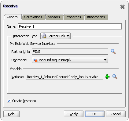
Retain the default name
Receive_1in the Name field. -
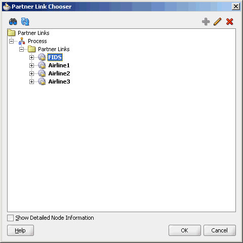
Click Browse Partner Links at the end of the Partner Link field. The Partner Link Chooser dialog is displayed.
-
Select FIDS, as shown in Figure 5-87, and click OK.
Figure 5-87 The Partner Link Chooser Dialog
Description of "Figure 5-87 The Partner Link Chooser Dialog"
-
Click the Auto-Create Variable icon to the right of the Variable field in the Receive dialog, as shown in Figure 5-88. The Create Variable dialog is displayed.
-
Select the default variable name and click OK. The Variable field is populated with the default variable name.
-
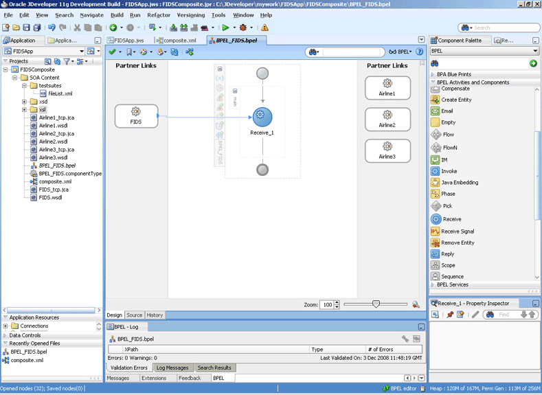
Check Create Instance, and click OK. The JDeveloper BPEL_FIDS.bpel page appears, as shown in Figure 5-89.
Figure 5-89 The JDeveloper - BPEL_FIDS.bpel
Description of "Figure 5-89 The JDeveloper - BPEL_FIDS.bpel"
-
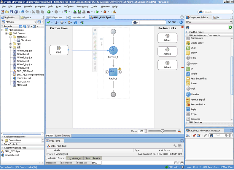
Drag and drop an Reply activity from the Component Palette to the design area, as shown in Figure 5-90.
Figure 5-90 The JDeveloper - BPEL_FIDS.bpel
Description of "Figure 5-90 The JDeveloper - BPEL_FIDS.bpel"
-
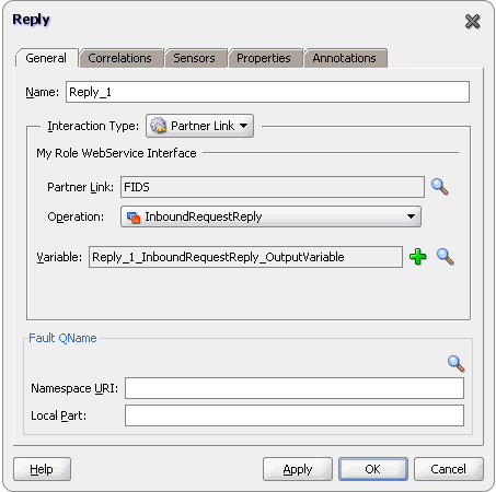
Double-click the Reply activity. The Reply dialog is displayed.
-
Retain the default name
Reply_1in the Name field. -
Click Browse Partner Links at the end of the Partner Link field. The Partner Link Chooser dialog is displayed.
-
Select FIDS, as shown in Figure 5-87, and click OK.
-
Click the Auto-Create Variable icon to the right of the Variable field in the Reply dialog. The Create Variable dialog is displayed.
-
Select the default variable name and click OK. The Variable field is populated with the default variable name, as shown in Figure 5-91.
-
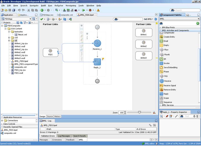
Click OK. The JDeveloper BPEL_FIDS.bpel page appears, as shown in Figure 5-92.
Figure 5-92 The JDeveloper - BPEL_FIDS.bpel
Description of "Figure 5-92 The JDeveloper - BPEL_FIDS.bpel"
-
Drag and drop a Flow activity from the Component Palette in between the Receive and the Reply activities in the design area, as shown in Figure 5-93.
Figure 5-93 The JDeveloper - BPEL_FIDS.bpel
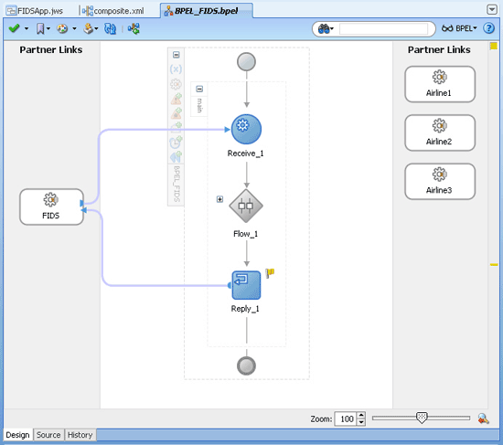
Description of "Figure 5-93 The JDeveloper - BPEL_FIDS.bpel"
-
Expand the Flow_1 activity. This displays a screen to create sequences.
Design the Flow for Airline1 Server
-
Drag and drop a Switch activity from the Component Palette to Sequence_1, as shown in Figure 5-94.
Figure 5-94 The JDeveloper - BPEL_FIDS.bpel Page
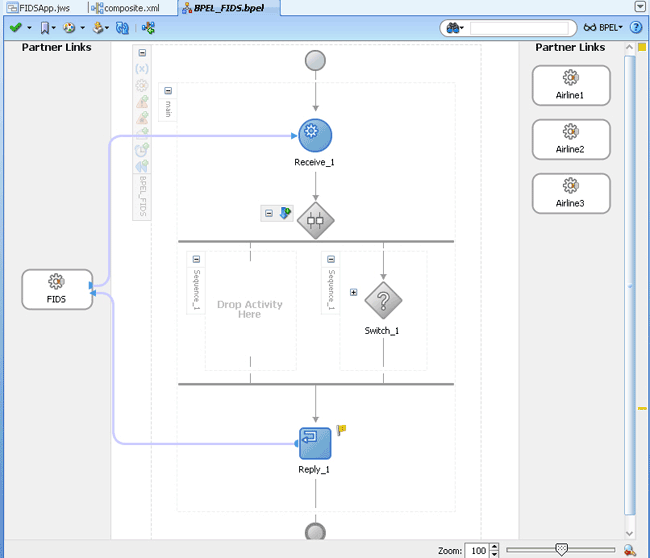
Description of "Figure 5-94 The JDeveloper - BPEL_FIDS.bpel Page"
-
Expand the Switch activity. This displays a screen to enter the values for <case> and <otherwise>.
-
In the
<case>section, click the View Condition Expression icon, as shown in Figure 5-95. The Condition Expression pop-up window is displayed.Figure 5-95 The JDeveloper - BPEL_FIDS.bpel Page
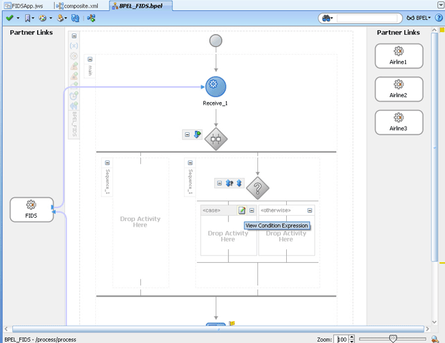
Description of "Figure 5-95 The JDeveloper - BPEL_FIDS.bpel Page"
-
Click the Xpath Expression Builder icon in the pop-up window. The Expression Builder dialog is displayed.
-
Enter
boolean(bpws:getVariableData('Receive_1_InboundRequestReply_InputVariable','FIDSProcessRequest','/ns5:FIDSProcessRequest/ns5:AirlineName')='Airline1')as the expression, as shown in Figure 5-96, and click OK. The screen returns to the Condition Expression pop-up window.Note:
This expression ensures that this flow is executed only when information for Airline1 is requested.Figure 5-96 The Expression Builder Dialog
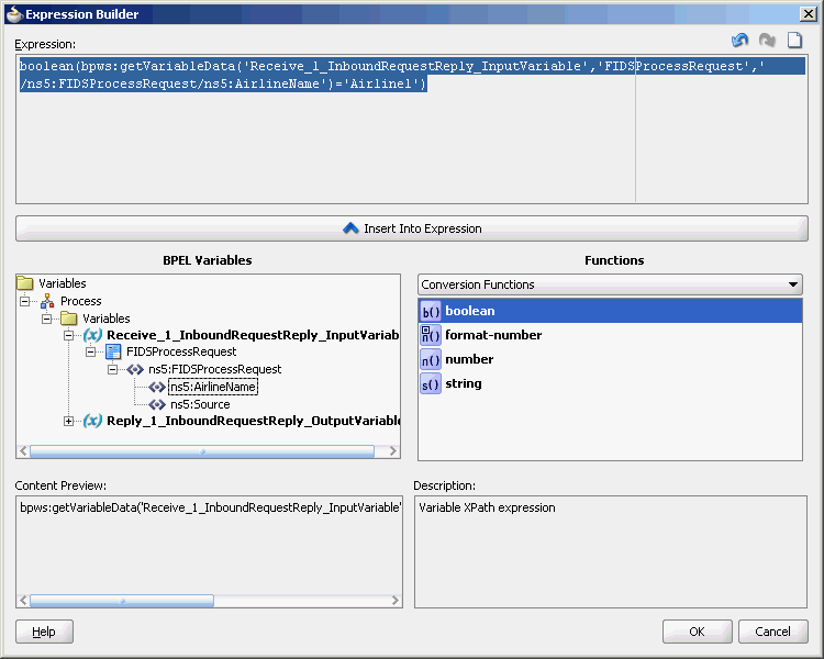
Description of "Figure 5-96 The Expression Builder Dialog"
-
Add an invoke activity to the <case> section.
-
Drag and drop an Invoke activity in the <case> section.
-
Double-click the Invoke activity. The Invoke dialog is displayed.
-
Click Browse Partner Links at the end of the Partner Link field. The Partner Link Chooser dialog is displayed.
-
Select Airline1, and click OK.
-
Click the Automatically Create Input Variable and the Automatically Create Output Variable icons to the right of the Input and Output Variable fields in the Invoke dialog. The Create Variable dialogs are displayed.
-
Select the default variable names and click OK. The Variable fields are populated with the default variable name. The Invoke dialog is displayed.
-
Click OK. The JDeveloper BPEL_FIDS.bpel page is displayed, as shown in Figure 5-97.
Figure 5-97 The JDeveloper - BPEL_FIDS.bpel
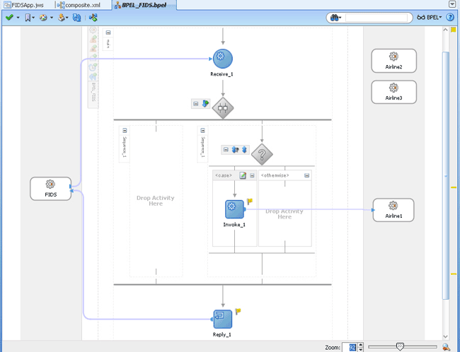
Description of "Figure 5-97 The JDeveloper - BPEL_FIDS.bpel"
-
-
Add an assign activity to the <case> section.
-
Drag and drop an Assign activity from the Component Palette before the Invoke_1 activity in the <case> section.
-
Double-click the Assign_1 activity. The Assign dialog is displayed.
-
Click the Copy Operation tab. The Assign dialog is displayed.
-
Select Copy Operation. The Create Copy Operation dialog is displayed.
-
Create the copy operation between the source from the input variable of the Receive_1 activity and the source from the input variable of the Invoke_1 activity, as shown in Figure 5-98.
Figure 5-98 The Create Copy Operation Dialog
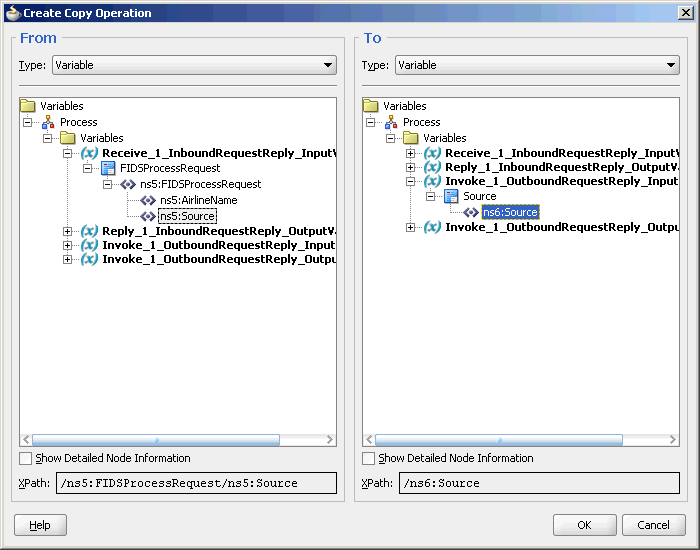
Description of "Figure 5-98 The Create Copy Operation Dialog"
-
Click OK in the Create Copy Operation dialog.
-
Click OK.
The BPEL_FIDS.bpel page is displayed, as shown in Figure 5-99.
Figure 5-99 The JDeveloper - BPELFIDS.bpel
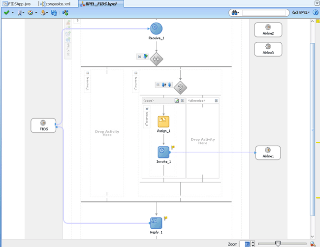
Description of "Figure 5-99 The JDeveloper - BPELFIDS.bpel"
-
-
Add a Transform activity to the <case> section.
-
Drag and drop a Transform activity in the <case> section, after the Invoke_1 activity.
-
Double-click the Transform activity.
-
Click the Transformation tab.
-
Click the Create...(Alt+N) icon. The Source Variable dialog is displayed.
-
Select Invoke_1_OutboundRequestReply_OutputVariable from the Source Variable list and click OK.
-
Select Reply_1_InboundRequestReply_OutputVariable from the Target Variable list.
-
Click OK. The XSL mapper tool is displayed.
-
Link the
tns:Flightnode from the source, on the left pane to the targetFlightDetailsnode on the right pane. The Auto Map Preferences dialog appears. -
Click OK. The Transformation_1.xsl (XSL mapper tool) is displayed, as shown in Figure 5-100.
Figure 5-100 The JDeveloper - Transformation_1.XSL Page
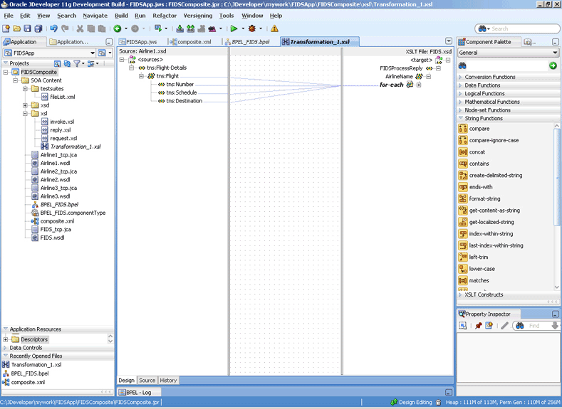
Description of "Figure 5-100 The JDeveloper - Transformation_1.XSL Page"
-
-
Click File, Save All. The BPEL_FIDS.bpel page is displayed, as shown in Figure 5-101, with the flow defined for the Airline1 server.
Figure 5-101 The JDeveloper - BPEL_FIDS.bpel
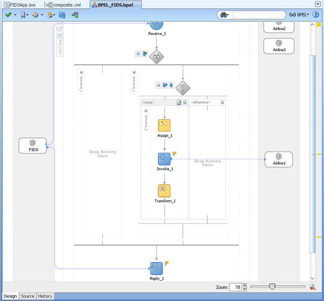
Description of "Figure 5-101 The JDeveloper - BPEL_FIDS.bpel"
Design the Flow for Airline2 Server
-
Double-click the empty Sequence activity and enter
Sequence_2in the Name field. -
Drag and drop a Switch activity from the Component Palette to Sequence_2.
-
Expand the Switch activity. This displays a screen to enter the values for <case> and <otherwise>.
-
In the
<case>section, click the View Condition Expression icon. The Condition Expression pop-up window is displayed. -
Click the Xpath Expression Builder icon in the pop-up window. The Expression Builder dialog is displayed.
-
Enter
boolean(bpws:getVariableData('Receive_1_InboundRequestReply_InputVariable','FIDSProcessRequest','/ns5:FIDSProcessRequest/ns5:AirlineName')='Airline2')as the expression, and click OK. The screen returns to the Condition Expression pop-up window.Note:
This expression ensures that this flow is executed only when information for Airline2 is requested. -
Add an invoke activity to the <case> section.
-
Drag and drop an Invoke activity in the <case> section.
-
Double-click the Invoke_2 activity. The Invoke dialog is displayed.
-
Click Browse Partner Links at the end of the Partner Link field. The Partner Link Chooser dialog is displayed.
-
Select Airline2, and click OK.
-
Click the Automatically Create Input Variable and the Automatically Create Output Variable icons to the right of the Input and Output Variable fields in the Invoke dialog. The Create Variable dialogs are displayed.
-
Select the default variable names and click OK. The Input and Output Variable fields are populated with the default variable names. The Invoke dialog is displayed.
-
Click OK. An Invoke activity is added to the JDeveloper BPEL_FIDS.bpel page under Sequence_2.
-
-
Add an assign activity to the <case> section.
-
Drag and drop an Assign activity from the Component Palette before the Invoke activity in the <case> section.
-
Double-click the Assign_2 activity. The Assign dialog is displayed.
-
Click the Copy Operation tab. The Assign dialog is displayed.
-
Select Copy Operation. The Create Copy Operation dialog is displayed.
-
Create the copy operation between the source from the input variable of the Receive_1 activity and the source from the input variable of the Invoke_2 activity, as shown in Figure 5-102.
Figure 5-102 The Create Copy Operation Dialog
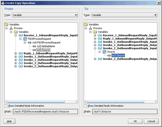
Description of "Figure 5-102 The Create Copy Operation Dialog"
-
Click OK in the Create Copy Operation dialog.
-
Click OK.
-
-
Create a temporary variable and add a Transform activity to the <case> section.
Note:
The temporary variable is used for storing flight details from the Airline2 server, which would later be appended to the reply variable.-
Click the Variables... icon represented by (x). The Variables dialog is displayed, as shown in Figure 5-103.
-
Click the Create... icon. The Create Variable dialog is displayed, as shown in Figure 5-104.
-
Select Message Type as the variable type.
-
Click the Browse Message Types icon at the end of the Message Type field. The Type Chooser dialog is displayed.
-
Click Message Types, Partner Links, FIDS, FIDS.wsdl, Message Types, and then FIDSProcessReply_msg_reply, as shown in Figure 5-105.
-
Click OK. The Message type field in the Create Variable dialog is populated with the FIDSProcessReply_msg_reply partner link.
-
Click OK. A variable, Variable_1, of type Message Type is added to the Variables list in the Variable dialog.
-
Click OK to return to the BPEL_FIDS.bpel page.
-
Drag and drop a Transform activity in the <case> section, after the Invoke_2 activity.
-
Double-click the Transform_2 activity.
-
Click the Transformation tab.
-
Click the Create... icon. The Source Variable dialog is displayed.
-
Select Invoke_2_OutboundRequestReply_OutputVariable from the Source Variable list and click OK.
-
Select Variable_1 from the Target Variable list.
-
Click OK. The XSL mapper tool is displayed.
-
Link the
tns:flightnode from the source, on the left pane to the targetFlightDetailsnode on the right pane. The Auto Map Preferences dialog appears, as shown in Figure 5-106.Figure 5-106 The Transformation_2.XSL Page With Auto Map Preference Dialog
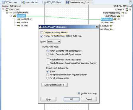
Description of "Figure 5-106 The Transformation_2.XSL Page With Auto Map Preference Dialog"
-
Click OK. The Transformation_2.xsl (XSL mapper tool) file with the XSL mapping is displayed.
-
-
Click File, Save All.
The BPEL_FIDS.bpel page is displayed, as shown in Figure 5-107, with the flow defined for the Airline2 server.
Figure 5-107 The JDeveloper - BPEL_FIDS.bpel
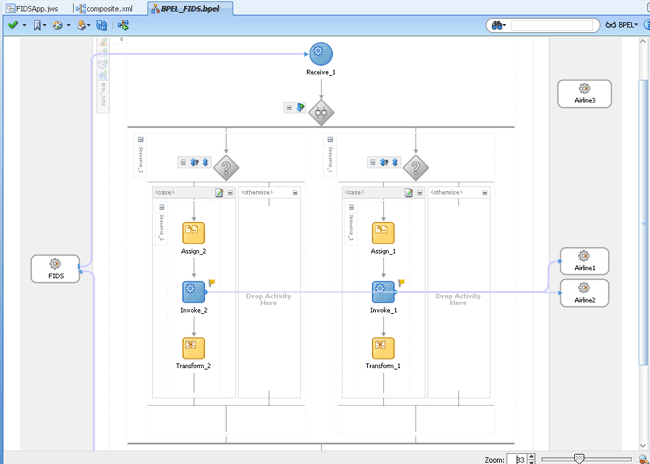
Description of "Figure 5-107 The JDeveloper - BPEL_FIDS.bpel"
Design the Flow for Airline3 Server
-
Right-click the Flow_1 activity. Click Add Sequence from the menu.
Sequence_3is added. -
Drag and drop a Switch activity from the Component Palette to Sequence_3.
-
Expand the Switch activity. This displays a screen to enter the values for <case> and <otherwise>.
-
In the
<case>section, click the View Condition Expression icon. The Condition Expression pop-up window is displayed. -
Click the Xpath Expression Builder icon in the pop-up window. The Expression Builder dialog is displayed.
-
Enter
boolean(bpws:getVariableData('Receive_1_InboundRequestReply_InputVariable','FIDSProcessRequest','/ns5:FIDSProcessRequest/ns5:AirlineName')='Airline3')as the expression, and click OK. The screen returns to the Condition Expression pop-up window.Note:
This expression ensures that this flow is executed only when information for Airline3 is requested. -
Add an invoke activity to the <case> section.
-
Drag and drop an Invoke activity in the <case> section.
-
Double-click the Invoke_3 activity. The Invoke dialog is displayed.
-
Click Browse Partner Links at the end of the Partner Link field. The Partner Link Chooser dialog is displayed.
-
Select Airline3, and click OK.
-
Click the Automatically Create Input Variable and Automatically Create Output Variable icon to the right of the Input and Output Variable field in the Invoke dialog. The Create Variable dialogs are displayed.
-
Select the default variable names and click OK. The Input and Output Variable fields are populated with the default variable names. The Invoke dialog is displayed.
-
Click OK. An Invoke activity is added to JDeveloper BPEL_FIDS.bpel page under Sequence_3.
-
-
Add an assign activity to the <case> section.
-
Drag and drop an Assign activity from the Component Palette before the Invoke activity in the <case> section.
-
Double-click the Assign_3 activity. The Assign dialog is displayed.
-
Click the Copy Operation tab. The Assign dialog is displayed.
-
Select Copy Operation. The Create Copy Operation dialog is displayed.
-
Create the copy operation between the source from the input variable of the Receive_1 activity and the source from the input variable of the Invoke_3 activity, as shown in Figure 5-108.
Figure 5-108 The Create Copy Operation Dialog
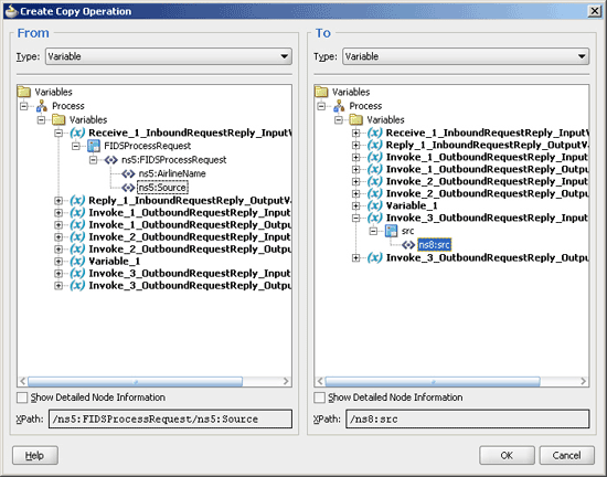
Description of "Figure 5-108 The Create Copy Operation Dialog"
-
Click OK in the Create Copy Operation dialog.
-
Click OK.
-
-
Create a temporary variable and add a Transform activity to the <case> section.
Note:
The temporary variable is used for storing flight details from the Airline3 server, which would later be appended to the reply variable.-
Click the Variables... icon represented by (x). The Variables dialog is displayed, as shown in Figure 5-109.
-
Click the Create... icon. The Create Variable dialog is displayed.
-
Select Message Type as the variable type.
-
Click the Browse Message Types icon at the end of the Message Type field. The Type Chooser dialog is displayed.
-
Click Message Types, Partner Links, FIDS, FIDS.wsdl, Message Types, and then FIDSProcessReply_msg_reply, as shown in Figure 5-105.
-
Click OK. The Message type field in the Create Variable dialog is populated with the FIDSProcessReply_msg_reply partner link.
-
Click OK. A variable, Variable_2, of type Message Type is added to the Variables list in the Variable dialog.
-
Click OK to return to the BPEL_FIDS.bpel page.
-
Drag and drop a Transform activity in the <case> section, after the Invoke_3 activity.
-
Double-click the Transform_3 activity.
-
Click the Transformation tab.
-
Click the Create... icon. The Source Variable dialog is displayed.
-
Select Invoke_3_OutboundRequestReply_OutputVariable from the Source Variable list and click OK.
-
Select Variable_2 from the Target Variable list.
-
Click OK. The XSL mapper tool is displayed.
-
Link the
tns:flightnode from the source, on the left pane to the targetFlightDetailsnode on the right pane. The Auto Map Preferences dialog appears. -
Click OK. The Transformation_3.xsl (XSL mapper tool) file with the XSL mapping is displayed, as shown in Figure 5-110.
Figure 5-110 The Transformation_3.XSL Page
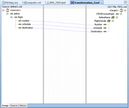
Description of "Figure 5-110 The Transformation_3.XSL Page"
-
-
Click File, Save All. The BPEL_FIDS.bpel page is displayed, as shown in Figure 5-111, with the flow defined for the Airline3 server.
Figure 5-111 The JDeveloper - BPEL_FIDS.bpel
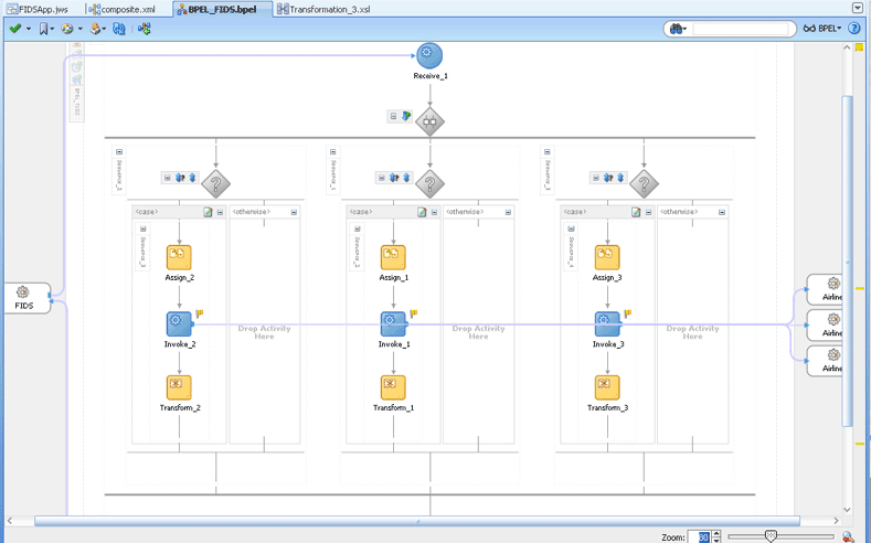
Description of "Figure 5-111 The JDeveloper - BPEL_FIDS.bpel"
-
Drag and drop an Assign activity from the Component Palette in between the Reply and Receive activities in the design area.
-
Double-click the Assign_4 activity. The Assign dialog is displayed.
-
Click the Copy Operation tab. The Assign dialog is displayed, as shown in Figure 5-112.
Figure 5-112 The Assign Dialog - Copy Operation Tab
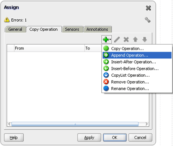
Description of "Figure 5-112 The Assign Dialog - Copy Operation Tab"
-
Select Append Operation. The Create Append Operation dialog is displayed.
-
Create an append operation to append the information stored in the temporary variable,
Variable_1, to the reply variable,Reply_1_InboundRequestReply_OutputVariable, as shown in Figure 5-113.Figure 5-113 The Create Append Operation Dialog
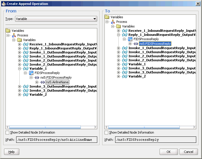
Description of "Figure 5-113 The Create Append Operation Dialog"
-
Click OK. The Assign dialog is displayed.
-
Select Append Operation. The Create Append Operation dialog is displayed.
-
Create another append operation to append the information stored in the temporary variable,
Variable_2, to the reply variable,Reply_1_InboundRequestReply_OutputVariable, as shown in Figure 5-114.Figure 5-114 The Create Append Operation Dialog
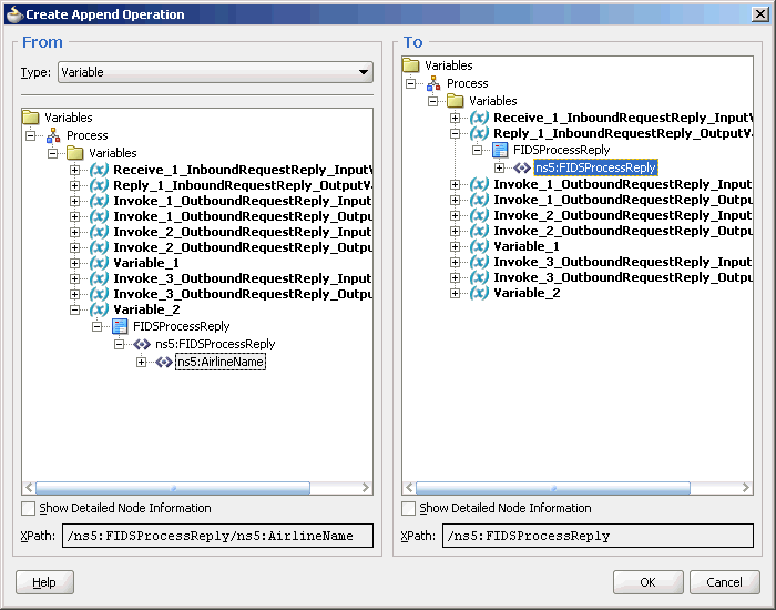
Description of "Figure 5-114 The Create Append Operation Dialog"
-
Click OK. The Assign dialog is displayed.
-
Click OK. The JDeveloper BPEL_FIDS.bpel page is displayed, as shown in Figure 5-115.
Figure 5-115 The JDeveloper - HelloWorldFlow.bpel
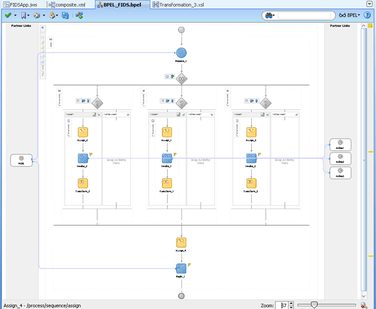
Description of "Figure 5-115 The JDeveloper - HelloWorldFlow.bpel"
-
Click File, Save All.
5.5.2.6 Deploying with JDeveloper
You must deploy the application profile for the SOA project and the application you created in the preceding steps. To deploy the application profile using JDeveloper, perform the following steps:
-
Create an application server connection. For more information, see Section 2.6, "Creating an Application Server Connection for Oracle JCA Adapters."
-
Deploy the application. For more information, see Section 2.7, "Deploying Oracle JCA Adapter Applications from JDeveloper."
You must run the Server and Client java programs to test the application. For more information, see the associated README file.
5.5.2.7 Monitoring Using the Fusion Middleware Control Console
You can monitor the deployed SOA composite using the Fusion Middleware Control Console. Perform the following steps:
-
Navigate to
http://servername:portnumber/em. The composite you deployed appears in the application navigator. -
Click the SOA composite that you deployed. The Dashboard is displayed.
Note your Instance ID in the Recent Instances area.
-
Click the Instances tab. The Instance IDs of the SOA composite are listed.
-
Click the Instance ID that you noted in Step 2. The Flow Trace page is displayed.
-
Click your BPEL process instance. The Audit Trail of the BPEL process instance is displayed.
-
Expand a payload node to view payload details.
-
Click the Flow tab to view the process flow. Additionally, click an activity (such as invoke, receive) to view the details of an activity.
