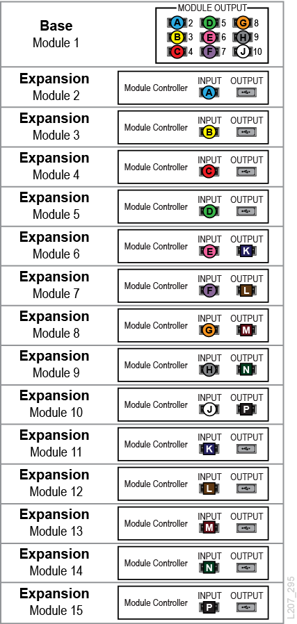
Cable the Expansion Modules
The Expansion Modules connect to the Base Module using USB cables.
Connect expansion interconnect cables between the ports listed in the table below or see the diagram below (matching letters connect together).
| These Output Ports: | Connect to: |
|---|---|
|
Base Module Output Port 2 |
Module 2 Controller Input Port |
|
Base Module Output Port 3 |
Module 3 Controller Input Port |
|
Base Module Output Port 4 |
Module 4 Controller Input Port |
|
Base Module Output Port 5 |
Module 5 Controller Input Port |
|
Base Module Output Port 6 |
Module 6 Controller Input Port |
|
Base Module Output Port 7 |
Module 7 Controller Input Port |
|
Base Module Output Port 8 |
Module 8 Controller Input Port |
|
Base Module Output Port 9 |
Module 9 Controller Input Port |
|
Base Module Output Port 10 |
Module 10 Controller Input Port |
|
Module 1 thru 5 Controller Output |
Do not connect anything. Leave dust cover in place. |
|
Module 6 Controller Output Port |
Module 11 Controller Input Port |
|
Module 7 Controller Output Port |
Module 12 Controller Input Port |
|
Module 8 Controller Output Port |
Module 13 Controller Input Port |
|
Module 9 Controller Output Port |
Module 14 Controller Input Port |
|
Module 10 Controller Output Port |
Module 15 Controller Input Port |
|
Module 11 thru 15 Controller Output |
Do not connect to anything. Leave dust cover in place. |
Figure 2-27 Cabling the Expansion Modules
