1.3 Components Diagram and Data Flow
This topic describes the various components of Weblogic JMS Server architecture that to be created.
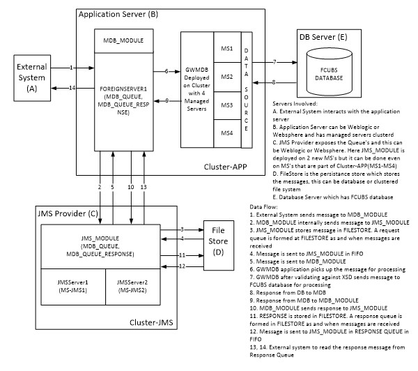
Below is the flow diagram which indicates various components that are used and the document explains the steps to create.
Figure 1-3 Components Diagram and Data Flow
Servers Involved -
- External System interacts with the application server.
- The application server can be Weblogic or Websphere and has managed servers clustered.
- JMS provider exposes the Queue and this can be Weblogic or Websphere. Here JMS_MODULE is deployed on 2 new MSs but it can be done even on MSs that are part of Cluster-APP(MS1-MS4).
- FileStore is the persistence store that stores the messages, this can be a database or clustered file system.
- Database Server which has FCUBS database.
Data Flow -
- External System sends a message to MDB_MODULE.
- MDB_MODULE internally sends a message to JMS_MODULE.
- JMS_MODULE stores messages in FILESTORE. A request queue is formed at FILESTORE as and when messages are received.
- The message is sent to JMS_MODULE in FIFO.
- The message is sent to MDB_MODULE.
- GWMDB application picks up the message for processing.
- GWMDB after validating against XSD sends a message to the FCUBS database for processing.
- Response from DB to MDB
- Response from MDB to MDB_MODULE
- MDB_MODULE sends a response to JMS_MODULE.
- RESPONSE is stored in FILESTORE. A response queue is formed in FILESTORE as and when messages are received.
- The message is sent to JMS_MODULE in RESPONSE QUEUE in FIFO.
- The message is sent to JMS_MODULE in RESPONSE QUEUE in FIFO.
Parent topic: Introduction
