12 Dynamic Attribute Mapping between UIM and ATA
This chapter describes how to perform the Dynamic Attribute mapping between UIM and ATA.
Dynamic Data Mapping from UIM
The dynamic data mapping takes advantage of UIM characteristics and provides maximum flexibility for mapping fields from UIM to the topology model.
The dynamic data mapping:
- Does not require any additions, updates, migrations, or deployments of your existing specifications.
- Guarantees the value is set correctly and does not require a user to select the correct value.
- Allows ATA to support data extensions to the topology model without an upgrade.
- Vertex and Edge Labels or Properties in ATA may require different names than Characteristics, or Attributes or Roles in the implemented UIM model.
- These items are supported through dynamic data mapping.
The examples are:
- UIM has a 'Vendor' attribute on the Logical Device and Equipment Specifications but some users have added 'manufacturer' to their Physical Device Specifications.
- Some vertices are not identified specifically in UIM such as Domain and Service Type. These values are implied based on the '5G' cartridge or the 'FTTx' cartridge but are not specifically identified on the entity.
Prerequisites for Dynamic Data Mapping from UIM
The prerequisites are as follows:
- The following configuration files are required:
- topologyAttributeMapping.json
- topologyRoleMapping.json
- topologySpecificationMapping.json.
- For traditional UIM, these files exist in the <domain>/UIM/config/topologyMappings directory. For a cloud native environment, the files exist in the $UIM_CNTK/charts/uim/config/topologyMappings directory.
- Files with these names plus the extension .sample are provided.
- Prior to migration, the correct configurations must be provided. Else, the data will not be mapped correctly to ATA.
- If the file does not exist an error occurs during UIM entity creation.
- If you want to skip this process, you can remove the .sample extension and proceed with the default settings.
Planning the Mapping
You can avoid mapping all characteristics to ATA if you have a large set of characteristics. Determine which characteristics are helpful for developing the proper answers to your topology questions.
For example, if you want to query all Router specifications:
- Identify all characteristics and specification names that identify a Router.
- Map those values to the PG_DEVICE.NODECATEGGORY column.
- Run a query
'Node Category' = 'Router'to display the topology for all your routers.
Another example is Vendor. If you identify your
<vendor1> devices by specification name or by
characteristics, map them to the PG_VENDOR Vertex. Once this is setup, you can
query all your <vendor1> Devices or combine it with the
previous examples and query all your vendor Routers. See ATA Model Documentation
for the full set of columns and vertices that are available.
Characteristics that are mapped as Properties are displayed when you select Properties on the Resource Drawer from the ATA canvas. If you have a large set of characteristics that are mapped to Properties, an alternate flow is recommended. If you use More Info from Resource Drawer and visualize the characteristics from the Resource Summary page, you see all attributes without impacting the performance.
Mapping the Dynamic Data from UIM
To map the dynamic data from UIM, the following definitions are required:
- vertex: A node in the Topology Model, examples are Vendor, Domain, Technology, Network Type, Device, Location
- property: A column on every vertex and edge in the Topology model.
- It supports JSON allowing for unlimited additional attributes.
- Property is the name of the key used to store the value retrieved from the UIM attribute.
- properties: Is an array defining how individual attributes of an entity are to be stored in Topology schema.
- columnName: An existing column on a physical table in the Topology Model used to store the attribute.
- name: Maps to different entity classes and entity specification classes. For example: “LogicalDeviceDAO”, “EquipmentSpecificationDAO”, “PlaceSpecificationDAO”, “PropertyLocationDAO” and so on.
The following POST operation creates a logical device, you can see the relationships and properties with which the dynamic properties are supported.
POST: http://localhost:8080/vertex
Body:
{"entityId":<entityID>,"entityVersion":<entityVersion>,"businessObjectClass":"LogicalDeviceDAO","id":"<ID>","name":"<name>","specName":"<specificationName>","latitude":0.0,"longitude":0.0,"inventoryStatus":"INSTALLED","referenceId":<referenceID>,"relationships":{"vendor":"<vendor>"},"properties":{"deviceIdentifier":"<deviceIdentifier>"}}Note:
- In this example, the TopologyAttributesMapping.json file provides the instructions to ATA and the file is available in the UIM/config/topologyMappings directory.
- The topologyAttributesMapping file is used to address hard coded attributes from UIM tables.
- See topologyAttributesMapping.json for more information.
The POST operation tells the topology:
- Map LogicalDevice.deviceIdentifier to the property deviceIdentifer.
- Map LogicalDeviceSpecification.vendorName to the vertex = vendor
- This is based on the UIM ClassName, it works with any Class or specification that is topology-enabled.
You can add a role to the Logical Device from the list of roles that are configured in the TopologyRoleMapping.json file.
You can see that GET that the Logical Device tracks the deviceIdentifier in the properties column using:
GET: http://localhost:8080/vertex/typeid/1/referenceid/<refID>
{"businessObjectClass":"LogicalDeviceDAO","entityId":<entityID>,"entityVersion":<entityVersion>,"id":"<versionID>","inventoryStatus":"INSTALLED","latitude":0.0,"longitude":0.0,"name":"<name>","properties":{"deviceIdentifier":"<deviceID>"},"referenceId":<referenceID>,"specName":"<specificationName>"}PUT: http://localhost:8080/vertex
{"businessObjectClass":"LogicalDeviceDAO","entityId":<entityID>,"entityVersion":3,"id":"<ID>","inventoryStatus":"INSTALLED","latitude":0.0,"longitude":0.0,"name":"<name>","properties":{"deviceIdentifier":"<ID>","transmission":"Optical_Transmission"},"referenceId":<refernceID>,"specName":"<specificationName>"}In the body:
- The role “Optical_Transmission” is mapped to the property field with name = “transmission”.
- The role was given a name = “transmission” which was provided by the UIM admin.
- Add, update and delete are supported. This works for Equipment and Physical Device (any topology-enabled entity that supports roles).
- Roles can be mapped to properties, vertices or columns.
The rules to perform this are:
- The Vertex must exist: The mapping can be performed to multiple vertices and can have multiple values.
- Property: There can be multiple properties. The UIM integrator is responsible for not having similar or misspelled values.
- ColumnName: A column can only have 1 value. The user is currently responsible for assuring this value is unique. It can be overlaid. This should be used for a queried attributes where an index is needed.
- The possible values of "columnName" are the following:
- PG_DEVICE - [ NODECATEGORY, MACADDRESS, IPV4, IPV4SUBNET, IPV6, IPV6SUBNET, ZONEID, DEVICEIDENTIFIER, NETWORKSTATUS, NODETYPE]
- PG_LOCATION - [DISTRICT, PROVINCE, OPERATOR, CITY, STATE, POSTALCODE, COUNTRY, AREA, CIRCLE]
- PG_COMMICATION - [FROMNODEDATA, TONODEDATA, RATECODE, TECHNOLOGY]
- PG_NETWORK - [CATEGORY, SUBCATEGORY, TOPOLOGYTYPE, SUBTYPE]
Note:
UIM currently supports city, state, country and postalcode attributes from the PropertyLocationDAO and PropertyAddressDAO. The street address or subunit (aptartment number, room number) are not supported.
The supported UIM classes are:
LogicalDeviceDAO, GeographicPlaceDAO, PhysicalDeviceDAO, NetworkDAO, NetworkEdgeDAO, EquipmentDAO, GeographicSiteDAO, PropertyLocationDAO
Note:
This includes the corresponding supported specification classes.
The last configuration is TopologySpecificationMapping.json.
- The related vertices field automatically adds a relationship edge between any instance of the specification to the vertex with the provided name and value.
- A characteristic does not need to be added and set on the specification to be tracked in topology.
- This allows our current RI cartridges to be used without any modifications.
- The characteristics column works the same as roles.
- It automatically adds a relationship to a vertex, sets properties or sets a column value.
- Any current characteristics can be used. No changes are needed.
PUT: http://localhost:8080/vertex
{"entityId":<entityID>,"entityVersion":<entityVersion>,"businessObjectTypeId":1,"businessObjectClass":"LogicalDeviceDAO","id":"<ID>","name":"<name>","specName":"router","latitude":<latitude>,"longitude":<longitude>,"inventoryStatus":"INSTALLED","isTopLevelNode":true,"nodeAvailable":true,"placeNode":false,"referenceId":<referenceID>,"createdUser":"test","lastModifiedUser":"test","relationships":{"vendor":"<vendor>","domain":"Ethernet"},"properties":{"deviceIdentifier":"<deviceID>"}}Customizing ATA Service Topology Configurations from UIM
From UIM, you can customize the ATA service topology configurations. You
update the required properties, that customize the service topology configurations in
ATA, from a JSON file: ServiceTopologyConfiguration_<serviceSpecName>.json. Each service
has its own JSON configuration file.
For traditional UIM, this service topology configuration JSON file is located in UIM_Home/config/topologyMappings. For a cloud native environment, the JSON file exists in UIM_CNTK/charts/uim/config/topologyMappings.
Service topology has an out of the box functionality to build a visualization for each service based on the resources available in the service configuration. You can customize the visualization to complete the end-to-end design as per your requirement.
For example:
- To add a custom node Internet to the end of the Broadband service and a custom edge to connect it to a router that is a resource on the service.
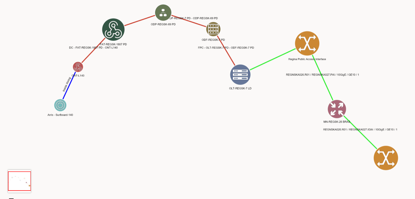
- To add a custom edge and label it Inside Wiring to show the connection from the CPE to the ONT.
The table lists the service topology configuration properties.
Note:
-
In the table below, nodes and edges that are added to support the topology visualization are referred to as TOPOLOGYONLY nodes or edges.
- You can use the custom icons, customlabels, custom line styles, custom colors and exclude nodes which are redundant or not important.
Table 12-1 Properties in the ServiceTopologyConfiguration_<serviceSpecName>.json File
| Property | Description |
|---|---|
|
configurationItemLabel |
This property sets the service item name for which a resource is assigned or referenced. Setting this property creates a node or edge for the resource. For any service item, this property is mandatory. For a TopologyOnly node, the item lable is
|
|
configurationItemParent |
This property sets the child service item. If the service item is not under a child service, you do not set this property. |
|
customLabelClass |
This property sets the custom class. Using this, you can customize the label of a node or an edge. This custom class overrides the values set by getNodeLabel and getEdgeLabel methods. |
|
exclude |
By default, all the service nodes and edges are added to the topology in ATA. To exclude any of these nodes and edges from being displayed, set this property to true. |
|
icon |
This property enables you to customize an icon. |
|
customType |
This property sets the custom type for a node. For TopologyOnly nodes, set the customType
value as |
|
sourceNode |
This property sets the source node for a TopologyOnly edge. The value for this property can be the name or label of the node. |
|
targetNode |
This property sets the target node for a TopologyOnly edge. The value for this property can be the name or label of the node. |
|
lineStyle |
This property sets the line style. The available values are solid, dot, and dash. |
|
lineColor |
This property sets the line color. |
The following figure shows the end-to-end view of a Broadband service using JSON customizations.
"FibreBroadband" : {
	"nodes": [
		{
			"configurationItemLabel" : "OLTPort", "exclude": "true"
		},
		{
			"configurationItemLabel" : "TransportNetwork", "exclude": "true"
		},
 		{
			"configurationItemLabel" : "VoiceNetwork" , "exclude": "true"
		}
	],
	"edges": [
		{
			"configurationltemLabel": "TOPOLOGYONLY31",
			"customLabelClass" : "oracle.communications.inventory.api-custom.CustomLabelClass",
			"sourceNode" : "CPE",
			"targetNode": "ONT”,
                     	"lineStyle": "SOLID",
                     	"lineColor": "BLUE"
		}
	]
}
Custom Labels
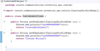
Custom labels require a custom class be deployed with your cartridge using Design Studio. An example of the Custom Label class used above.
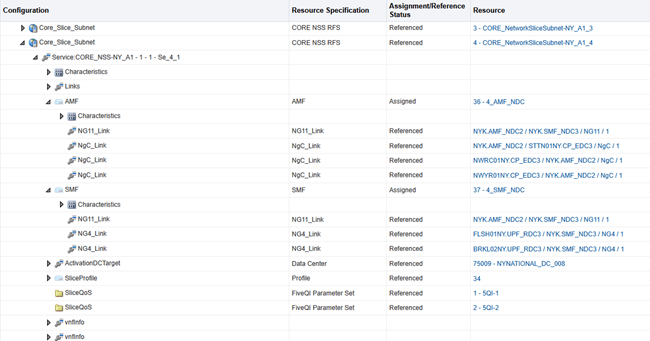
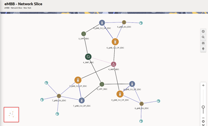
See the ServiceTopologyConfiguration_NetworkSlice.json.sample in UIM_Home/config/topologyMappings for the following Network Slice Service and Service Topology visualization.
Impact Analysis Customer Mappings
By default, parties associated with the impacted entities are not considered as the impacted customers. Based on your requirement, you can track the impacted customers using the configuration file. By specifying these mappings, you can control which customers are included in the impact analysis results when specific entities are impacted by network events or changes.
To achieve this filtering, provide the configuration in a JSON file. The location of this file is as follows:
-
File location in UIM CNTK: $UIM_CNTK/charts/uim/config/siaMappings/partyRoleMappings.json
File location in a standalone installation: <DOMAIN_HOME>/UIM/config/siaMappings/partyRoleMappings.json
After making any changes to partyRoleMappings.json, restart UIM to make the mappings effective.
About JSON File Structure
The partyRoleMappings.json file is organized by entity type, with each entity type containing multiple entity specifications. For each entity specification, you can define the required party specifications and roles as impacted customers.
High-level Structure
{
  "EntityTypeDAO": [
    {
      "entitySpecification": "SpecificationName",
      "parties": [
        {
          "partySpecification": "PartySpecName",
          "roles": ["Role1", "Role2", ...]
        }
      ]
    }
  ]
}
Where:
EntityTypeDAOrepresents the inventory entity type (for example, ServiceDAO, LogicalDeviceDAO).entitySpecificationdefines the specific type of entity within the category.partiescontains an array of party specifications and their associated roles.partySpecificationdefines the type of party (for example, Individual, Business)roleslists the roles that the party must be considered as impacted.
Supported Entity Types
The following entity types are supported in the mapping file:
- ServiceDAO: Service entities (such as FibreBroadband, AccessService)
- LogicalDeviceDAO: Logical device entities (such as routers, switches)
- PhysicalDeviceDAO: Physical device entities (such as hardware devices)
- EquipmentDAO: Equipment entities (such as chassis, cards)
- PipeDAO: Connectivity entities (such as links, channels)
Note:
Adding, viewing, editing, or deleting party associations for Logical Device, Physical Device, Equipment, Pipe, and Connectivity entities is not currently supported in UIM. However, party associations for these entities can be performed using Bulk Loader or APIs.
Examples for Impact Analysis Customer Mappings
Example: Service Entity Mappings
"ServiceDAO": [
  {
    "entitySpecification": "FibreBroadband",
    "parties": [
      {
        "partySpecification": "Individual",
        "roles": ["Customer"]
      }
    ]
  }
]
When a FibreBroadband service is impacted, the system identifies parties with
specification Individual that have the role
Customer associated with this service. These parties are then
included as impacted customers in the analysis results.
Example: Multiple Roles for a Party Specification
"LogicalDeviceDAO": [
  {
    "entitySpecification": "Ciena 6500",
    "parties": [
      {
        "partySpecification": "Individual",
        "roles": ["Customer", "ServiceOwner", "TechnicalContact"]
      }
    ]
  }
]
For Ciena 6500 logical device, the individuals with any of the roles
Customer, ServiceOwner, or
TechnicalContact will be considered as impacted parties.
Example: Multiple Party Specifications
"EquipmentDAO": [
  {
    "entitySpecification": "Ciena 6500-2 Chassis",
    "parties": [
      {
        "partySpecification": "Individual",
        "roles": ["Customer"]
      },
      {
        "partySpecification": "Business",
        "roles": ["EnterpriseCustomer", "ManagedServiceClient"]
      }
    ]
  }
]
For Ciena 6500-2 Chassis equipment the following roles will be
considered as impacted parties.:
- The
Individualparties withCustomerroles. - The
Businessparties withEnterpriseCustomerorManagedServiceClientroles.
Configuring the Mapping File
Adding a New Entity Specification
To add a new entity specification to the mapping file:
- Identify the required entity type (ServiceDAO, LogicalDeviceDAO, and so on).
- Add a new entry with the entity specification name.
- Define the party specifications and roles that should be associated with it.
An example for adding a new GPON service mapping is as follows:
"ServiceDAO": [
  {
    "entitySpecification": "GPONService",
    "parties": [
      {
        "partySpecification": "Individual",
        "roles": ["Customer", "Subscriber"]
      },
      {
        "partySpecification": "Business",
        "roles": ["EnterpriseCustomer"]
      }
    ]
  }
]
Modifying Existing Mappings
To modify an existing mapping:
- Locate the entity specification in the file.
- Add or remove party specifications and roles as needed.
- After making any changes to partyRoleMappings.json, restart UIM to get the changes updated.
An example for updating an existing mapping to add a new role is as follows:
// Original mapping
"PipeDAO": [
  {
    "entitySpecification": "DWDM_Optical_Fiber",
    "parties": [
      {
        "partySpecification": "Individual",
        "roles": ["Customer"]
      }
    ]
  }
]

// Updated mapping with new role
"PipeDAO": [
  {
    "entitySpecification": "DWDM_Optical_Fiber",
    "parties": [
      {
        "partySpecification": "Individual",
        "roles": ["Customer", "ServiceUser"]
      }
    ]
  }
]


