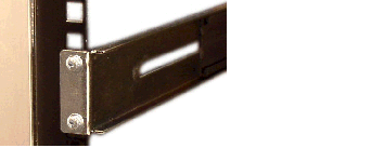
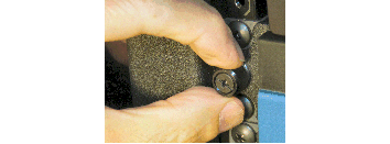
Cabinet-style 4-Post Chassis Installation

The following sections explain how to mount the Acme Packet 4900 in a cabinet-style, 4-post equipment rack.

Mounting System

Oracle provides flexible mounting options for your Acme Packet 4900 equipment rack installation.

The mounting system consists of a slide rail mounted on each side of an equipment rack and a chassis slide rail mounted on each side of the Acme Packet 4900 chassis. Once the slide rails are installed on the equipment rack and chassis, the chassis can be slid into place by aligning the installed chassis slide rails along the guides on the equipment rack slide rails. When the Acme Packet 4900 is fully inserted into the equipment rack, it is secured in place with two captive thumbscrews.

Installing the Equipment Rack Slide Rails

In the first stage of system installation, secure the equipment rack slide rail to the equipment rack. The equipment rack slide rail can expand and contract to accommodate equipment racks of various depths up to 32”.

You can mount the equipment rack slide rail to both tapped hole rack and square rack. Follow the appropriate procedure below.

Installing Slide Rails into a Tapped-Hole Rack

This section explains how to mount the Acme Packet 4900 slide rail assembly into a tapped-hole equipment rack.

Note:

The following procedure presumes that the tapped hole size is #10-32. If alternate tapped holes are used, the customer must supply the proper screws.
To install the slide rails to the front of a tapped-hole equipment rack:
  1. Locate the following components:
    • Assembled equipment rack slide rails (2)
    • #10-32 x 5/8” screws (8)
    • Mounting spacers (2)
  2. Line up the equipment rack slide rail with an appropriate mount point on the front of the equipment rack.
    Image showing aligning the Slide Rail Front Mount Point in a Tapped-Hole Rack
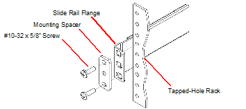
  3. For both holes in the flange, place one #10-32 x 5/8” screw through the mounting spacer, then through the slide rail flange and into the tapped hole.
    Image showing attaching the Slide Rail to a Tapped-Hole Rack
  4. Using a #2 Phillips head screwdriver, tighten the screws to secure the slide rail to the equipment rack. Do not completely torque the screws; leave a small amount of play at this time.
    Image showing installed Slide Rail in a Tapped-Hole Rack - Front Mount Point
  5. Expand and line up the equipment rack slide rail on the outside of the rear rack slide rail at the same height used for the front mount point.
    Image showing aligning Rear Mount Points of the Slide Rail in a Tapped-Hole Rack
  6. For both holes in the slide rail flange, place one #10-32 x 5/8” screw through the flange and into the tapped hole, and screw them into place.
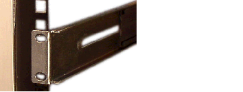
    Image showing installed Slide Rail in a Tapped-Hole Rack - Rear Mount Point
  7. Repeat Steps 2 and 6 for the other test equipment slide rail.
    Image showing installed Slide Rails in a Tapped-Hole Rack - Front Mount PointsImage showing Installed Slide Rails in a Tapped-Hole Rack - Rear Mount Points

Installing Slide Rails into a Square-Hole Rack

This section explains how to mount the Acme Packet 4900 slide rail assembly into a square-hole equipment rack. The customer can use #10-32, 1/4-20, M5 or M6 cage nuts as an alternative, but the cage nuts will be customer-supplied along with the associated mounting screws for the cage nut selected.

To install the slide rails on the front of a square-hole equipment rack:
  1. Locate the following components included in the rail kit box:
    • Equipment rack slide rails (2)
    • #10-32 x 5/8” screws (8)
    • Mounting spacers (2)
    • Nut bars (2)
  2. Line up the painted side of the stationary rail with an appropriate mount point on the front of the equipment rack.
    Image showing Aligning the Slide Rail Front Mount Point in a Square-Hole Rack
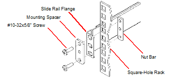
  3. For each of the two holes in the slide rail flange, place a #10-32 screw through the mounting spacer, then through the slide rail flange, and finally through the square hole in the rack rail.
    Image showing Attaching the Slide Rail to a Square-Hole Rack
  4. Hold the nut bar behind the front rack rail.
  5. Using a #2 Phillips head screwdriver, tighten the screws to secure the slide rail to the equipment rack. Do not completely torque the screws; leave a small amount of play at this time.
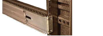
    Image showing Installed Slide Rail in a Square-Hole Rack - Front Mount Point
  6. Expand and line up the unpainted side of the stationary rail flange on the outside of the rear rack rail at the height used for the front mount point.
    Image showing Aligning the Slide Rail Rear Mount Point in a Square-Hole Rack
  7. Hold the nut bar behind the rear rack slide rail.
  8. Place one #10-32 screw through each of the holes in the slide rail flange, then through the square hole in the rack, and finally into the nut bar.
  9. Using a #2 Phillips head screwdriver, tighten the screws securely into place.
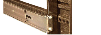
    Image showing Installed Slide Rail in a Square-Hole Rack - Rear Mount Point
  10. Torque the screws on the front and back of the rail slide.
  11. Repeat this procedure for the other slide rail.

Installing the Chassis Flanges and Slide Rails

In this second portion of system installation, two chassis flanges and two chassis slide rails are secured to the Acme Packet 4900 chassis.

To install the chassis rail slides on the Acme Packet 4900 chassis:
  1. Locate the following components:
    • #6-32 x 1/4" flat head screws (6) (in accessory kit box)
    • Front-mounting flanges (2) (in accessory kit box)
    • #6-32 x 5/16" pan head screws (6) (in rail kit box)
    • Chassis slide rails (2) (in rail kit box)
    • #2 Phillips screwdriver
  2. Line up one chassis flange with the tapped holes. Position the chassis flange’s spring-loaded thumbscrew toward the front panel of the system.
    Image showing tapped Holes to Accommodate Front-Mounting Flange
  3. Insert 2 x #6-32 x 5/16" flat head screws into the flange and chassis, and using a #2 Phillips screwdriver, tighten the screws to secure the flange to the chassis.
    Image showing Front-Mounting Flange Installed
  4. Line up the chassis slide rail with the Acme Packet 4900 side panel. Position hole #4 closest to the flange at the front of the Acme Packet 4900 chassis. Line up the keyhole slot on the slide rail with the keyhole button on the side of the Acme Packet 4900 and slide the rail slightly backwards to secure the slide. When you do this, holes #4, #2, and #3 on the slide will line up with the corresponding tapped holes on on the chassis.
    Image showing tapped Holes to Accommodate Chassis Slide Rail
  5. Use #6-32 x 5/16" screws to secure the chassis slide rail to the side of the Acme Packet 4900.
    Image showing Acme Packet 4900 with Chassis Slide RailImage showing Acme Packet 4900 with Installed Chassis Slide Rail
  6. Repeat this procedure for the other side of the Acme Packet 4900 chassis.

Installing the Chassis in the Rack

The Acme Packet 4900 is now ready to be installed into a 4-post equipment rack. To prevent personal injury or damage to the Acme Packet 4900, follow these guidelines:
  • This installation requires two people and should not be attempted otherwise.
  • Follow your organization’s best practices for lifting and installing heavy components into an equipment rack.
  • Ensure that the Acme Packet 4900 chassis remains supported until you have completely installed it into the equipment rack.
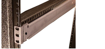
To install the Acme Packet 4900 chassis into the equipment rack:
  1. Lift the Acme Packet 4900 into the correct position to prepare to be installed into the equipment rack.
  2. Line up the chassis slide rails in back of the chassis with the guides in front of the equipment rack slide rails.
    Image showing equipment Rack Slide Rail Guides
  3. If necessary, press in the latches on either side of the Acme Packet 4900 in order for the assembly to slide into the guides.
  4. Push the Acme Packet 4900 fully into the equipment rack.
  5. Line up the chassis-mounted thumbscrews with the threads on the Acme Packet 4900 mounting spacer. You may have to adjust the spacer locations before they line up with the Acme Packet 4900’s captive screws.
    Image showing tightening the Thumbscrews to Secure the Chassis to the Rack
  6. Once correctly positioned, hand-tighten the thumbscrews into the mounting spacer and secure the chassis in the rack.
  7. Torque the two captive thumbscrews using a #2 Phillips screwdriver.
  8. Torque all four #10-32 x 5/8” front screws that hold the slide rails to the rack.