6 Maintenance
This chapter explains Acme Packet 4600 System hardware maintenance procedures. This chapter also provides hardware alarm information.
System Shutdown
Alhough several user-replaceable components of the Acme Packet 4600 are hot-swappable, some limited Acme Packet 4600 maintenance procedures require that you shut down the system.
Before you shut down or restart the Acme Packet 4600, ensure that there are no active calls in progress. The command to show active calls is “show sessions.”
ACMEPACKET# show sessionsProcedures to reroute call and network traffic around the Acme Packet 4600 are outside the scope of this guide.
You can set the Acme Packet 4600 to reject all incoming calls from your system with the set-system-state command. When set to offline, this command lets calls in progress continue uninterrupted, but no new calls are admitted.
After all call processing has stopped, you can power off your Acme Packet 4600. Shutting down the system is appropriate when you are replacing a physical interface card, power supply, or are removing the Acme Packet 4600 from the equipment rack.
Shutting Down the Acme Packet 4600 System
- In Superuser mode, type halt and then press <Enter>.
- To confirm the halt request, type Y and then press <Enter>.
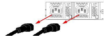
- When the console indicates shutdown is completed, unplug the AC power cords from the power supplies on the rear panel of the Acme Packet 4600.
- Confirm that the graphic display is dark and all fans are off.
Rebooting, Resetting, and Power Cycling
Reboot
Rebooting the Acme Packet 4600 shuts down the system in an orderly fashion and then automatically restarts it. The operating system gracefully shuts down as processes are terminated and the file system is stopped. While the system and its processes are stopped, all call processing is immediately halted. You may therefore wish to perform tasks that call for a reboot during off-peak maintenance hours.
Rebooting the Acme Packet 4600 is required every time you upgrade with a new version of the Acme Packet 4600 software.
Save your configurations before rebooting the Acme Packet 4600. Refer to the Maintenance and Troubleshooting Guide for a full explanation of this procedure. The save-config command is used to save the configuration in the example below.
For a full explanation and all options for the reboot command used in the example below, refer to the ACLI Reference Guide .
To reboot the Acme Packet 4600:System Reset
Resetting the Acme Packet 4600 via the reset pushbutton on the front of the chassis performs a cold reboot. This action is the equivalent of disconnecting the power from the system and then reconnecting it. There is no orderly termination of tasks, and the system shuts down abruptly. You should only reset the Acme Packet 4600 when it becomes unstable and no other means of gaining administrative control is possible.
During a system reset, certain files are not closed properly, and they may become corrupted. If an unclean shutdown is detected, filesystem recovery/repair will be run to ensure the system returns to a stable state. Filesystem verification also runs every 30 boots as a precautionary measure.
Note:
Always try to first reboot the Acme Packet 4600 from the ACLI before performing a cold reset. Only reset the system as a last resort.- Insert a rigid paperclip-sized tool into the small hole on the front of the
chassis beneath the graphic display. The system immediately resets and begins
its initialization and boot sequence.

Power Cycling
Power Cycling the Acme Packet 4600 is the process of turning the chassis off and then on again. Unplugging the power cords from the power supplies means to remove power from the system. When power cycling, it is imperative that you wait at least 10 seconds between power down and power up to ensure that all components are completely powered down before restarting the system.
Fault Recovery
On the Acme Packet 4600, certain unexpected power events can cause the Ethernet ports to enter a 'NotReady' state. If this happens and you have not enabled fault-recovery rebooting, you must manually power cycle the system to restore normal functionality. Because the Ethernet ports are down, you cannot power cycle over the network.
You can identify this problem by finding PCIe link lost
in the kernel.log file.
Hotswap event: PHY0 Hotswap status reg: 0x05
Hotswap event: PHY0 not ready
Hotswap event: PHY0 latch closed
Hotswap event: PHY0 present
pcieport 0000:02:08.0: pciehp: Slot(72): Link Down
pcieport 0000:02:08.0: pciehp: Slot(72): Already disabled
pcieport 0000:02:08.0: pciehp: Slot(72): Card present
pcieport 0000:02:08.0: pciehp: Slot(72): Latch open
igb 0000:0d:00.0 wancom0: PCIe link lost
igb 0000:0d:00.2 wancom2: PCIe link lost
igb 0000:0d:00.1 wancom1: PCIe link lost
bmr464 i2c-34/34-0036 POL fault in status reg 0x79: 0x8860
bmr464 i2c-34/34-0036 POL fault in status reg 0x7a: 0x0080
igb 0000:0d:00.3 eth3: PCIe link lost
If you've encountered this problem, Oracle recommends enabling fault-recovery rebooting to automatically restore your system. With this enabled, the Acme Packet 4600 gracefully shuts down and restarts when it detects all the Ethernet ports have gone down. To enable automatic fault recovery, navigate to the system-config element and set the fault-recovery attribute to enabled.
ORACLE# conf term
ORACLE(configure)# system
ORACLE(system)# system-config
ORACLE(system-config)# select
ORACLE(system-config)# fault-recovery enabled
ORACLE(system-config)# done
By default this parameter is disabled.
Standby State for HA Nodes
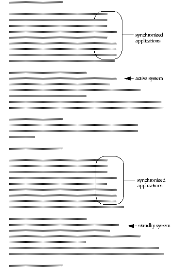
When performing hardware maintenance on the Acme Packet 4600, it is best to minimize any risk of interrupting network traffic or losing data. If the Acme Packet 4600s are configured as an HA node, you should only work on the Acme Packet 4600 that is in standby state.
- If you are in the same physical location as the Acme Packet 4600 you can view the graphic display on the front panel. The display will indicate the HA state. A standby system displays (S) while an active system does not display (S).
- If you are not in the same physical location as the Acme Packet 4600, you can use the ACLI show health command. The output of this command indicates the current HA state of the Acme Packet 4600.
Once you have determined that the Acme Packet 4600 due for maintenance is in standby state, you can continue with the appropriate procedures to replace a part.
If you need to perform maintenance on the active Acme Packet 4600 you need to manually force the two Acme Packet 4600s to switch HA states. Forcing a switchover renders the currently active Acme Packet 4600 in Standby state, and the current standby Acme Packet 4600 will assume all traffic processing and forwarding as the active system.
Note:
This procedure is only applicable to Acme Packet 4600 in an HA deployment.Replacing an NIU in an HA Node
- Prepare all equipment connected to the NIU for the NIU’s removal from the network.
- Force the system into standby state.
- Remove the NIU as described in this document.
- Log in to the ACLI via a console connection.
- Reboot the system from the ACLI.
Chassis Removal
Note:
You must first review the safety precautions for the Acme Packet 4600 prior to removing from an equipment rack.Note:
Always disconnect the Acme Packet 4600 power supplies from the power source when removing a chassis from an equipment rackPower Supply Removal and Replacement
This section explains how to remove and replace the power supplies in the Acme Packet 4600 chassis.
Note:
After physically unplugging a power supply, disconnect it from the power source before you remove or install it in the chassis.The power supply is a user-replaceable component. If an Acme Packet 4600 power supply malfunctions, you should remove the malfunctioning power supply and replace it.
Note:
Power supplies can be removed from the chassis while it is still installed in the rack and while the second power supply is providing system power; this is called a warm swap.Note:
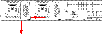
When removing and replacing a power supply, remember to first ground yourself using appropriate ESD grounding equipment such as a wrist strap.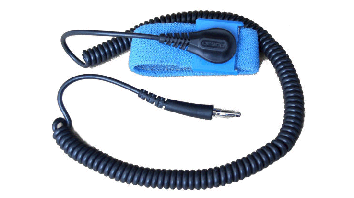 To remove a power supply from the Acme Packet 4600 chassis:
Installing a Power Supply
- Locate the power supply to be installed.
- Locate the empty power supply slot in the chassis.
- Insert the power supply into the empty power supply slot located on the rear
panel of the Acme Packet 4600 chassis. The labels on the power supply face
upward.
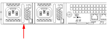
- Push the power supply handle until the power supply is engaged with the mid plane.
- The power supply is installed in the Acme Packet 4600 chassis.

- Connect the power cord to the inserted power supply.
NIU Removal and Replacement
Note:
Make sure you are properly grounded with an ESD strap before removing the NIU.Replacing the SSM3 Module
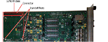
The SSM3 module that provides TLS security functionality to the Acme Packet 4600 is installed on the NIU PCB as shown below. There is a single connector located on the edge of the NIU into which the SSM3 module plugs; this connector supports one side of the module while the other side of the SSM3 module rests on four standoff posts.
Pre-Installation Guidelines
- The SSM3 module can be installed only in the designated location.
- Note the installation location of the SSM3 module on the NIU PCB.
- Ground yourself and follow proper ESD grounding procedures.
- Remove the SSM3 from the shipped packaging.
- Install the SSM3 according to the procedure below.
- This upgrade should be performed during low-traffic periods or during times of scheduled maintenance.
- Follow industry-standard procedures to ensure ESD protection.
- When installing or removing an NIU card, move the card to an ESD-safe location.
Note:
Before handling a Acme Packet 4600 Transcoding NIU card, follow the proper ESD grounding procedures. Failure to do so could damage the NIU card and its components.Required Parts
- ESD wrist strap
- ESD safe location
- SSM3 Module
- NIU Card
Removing the SSM3 Module
- Provide an ESD-safe location to place the SSM3 and NIU card.
- Wear an ESD wrist strap or take similar equivalent actions to prevent static damage to the NIU card or other ESD-sensitive components.
- Note the location of the SSM3 module connector on the NIU card.
- #2 Phillips screwdriver
- Remove the NIU card as directed in this guide.
- Place the NIU card on an ESD-safe mat or other similar location.
- Using the Phillips screwdriver, remove the four standoff screws from the SSM3
module and store them for later reuse.
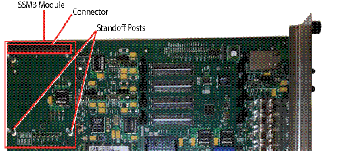
- To remove the module (shown below), grasp the SSM3 module along either side of
the connector between your thumb and index finger and pull up on one side of the
connector until the module is fully disconnected from the connector. Place the
module on an ESD-safe surface.

Installing the SSM3 Module
- Wear an ESD wrist strap or take similar equivalent actions to prevent static damage to the NIU card or other ESD-sensitive components.
- Place the new SSM3 module in an ESD-safe location.
- Note the location of the SSM3 module connector on the NIU card.
- #2 Phillips screwdriver
- Standoff screws (stored after removing the SSM3 module or available with the new SSM3 module)
- Grasp the SSM3 module along either side of the connector between your thumb and
index finger and join the module connector to the NIU connector by pressing
evenly across the connector until the module is fully seated (see below).
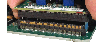
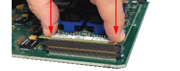
- Press evenly across the top of the connector to fully seat the SSM3 module on
the NIU PCB as shown below. Note that the SSM3 is fastened to the connector at
one end while at the other end, the board rests on two standoffs attached to the
NIU as shown in the figures below.
- Using the Phillips screwdriver, insert and tighten the four standoff screws to secure the SSM3 module to the PCB.
- Replace the NIU in the Acme Packet 4600 chassis.
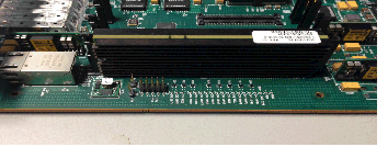
Replacing Transcoder DSP Modules

Note:
Never remove the heatsink from the transcoder DSP modules.There are slots for installing the transcoder DSP modules in two locations on the PCB
(two groups - the first of eight slots, and the second of four slots- See Figure 6 -
122). Transcoder DSP modules should be installed consecutively in numerical order,
starting with slot 0. 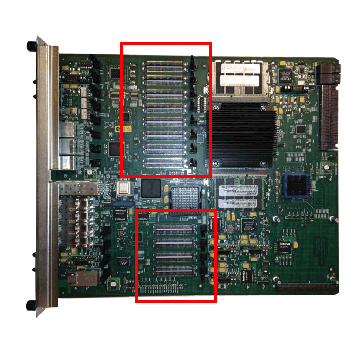
Installation and Removal Guidelines
- The transcoder DSP module can be installed only in the designated location.
- Note the installation locations of the transcoder DSP modules on the NIU PCB.
- Ground yourself and follow proper ESD grounding procedures.
- Remove the transcoder DSP module from the shipped packaging.
- Remove and install the transcoder DSP module according to the procedures below.
- The installation of these modules should be performed during low-traffic periods or during times of scheduled maintenance.
- Follow industry-standard procedures to ensure ESD protection.
- When installing or removing an NIU card, move the card to an ESD-safe location.
Note:
Before handling a Acme Packet 4600 NIU card, follow the proper ESD grounding procedures. Failure to do so could damage the NIU card and its components.Required Parts
- ESD wrist strap
- ESD-safe location
- Transcoder DSP module
- NIU Card
Removing the Transcoder DSP Module
- Provide an ESD-safe location to place the transcoder DSP module and NIU card.
- Wear an ESD wrist strap or take similar equivalent actions to prevent static damage to the NIU card or other ESD-sensitive components.
- Note the location of the transcoder DSP module connector on the NIU card.
- Remove the NIU card as directed in this guide. See See NIU Removal and Replacement.
- Place the NIU card in an ESD-safe location.
- To remove the module (as shown in the photos below), use a fingertip to release
the catch holding either end of the transcoder DSP module.
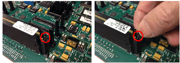
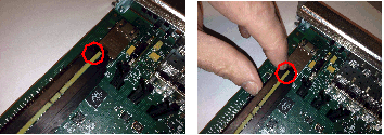
- Once the fasteners are detached from both sides of the transcoder DSP module,
hold the center of the module between your finger and thumb and slowly remove
the module. Be careful to keep the module level while removing it and guide it
smoothly through the guide slots on either side.

- Place the transcoder DSP module on an ESD-safe antistatic surface.
Installing the Transcoder DSP Module
- Place the new transcoder DSP module in an ESD-safe location.
- Wear an ESD wrist strap or take similar equivalent actions to prevent static damage to the NIU card or other ESD-sensitive components.
- Note the location of the transcoder DSP module connector on the NIU card.
- Grasp the transcoder DSP module between your thumb and index finger and line up
both sides of the module with the slot guides attached to the NIU PCB (see
below).
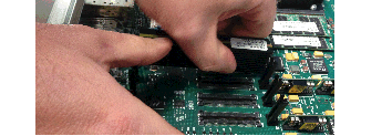
- Using your thumb on your other hand, guide the module evenly into the slot
guides located on each side as you lower the component into the connector. Press
evenly across the top of the connector to fully seat the transcoder DSP module
on the NIU PCB as shown below. Note that the module is fastened to the connector
at one end while at the other end, the board rests on two standoffs attached to
the NIU as shown in the figures below.
Upgrading or Replacing a Solid State Drive
This section explains how to upgrade or replace the Solid State Drive (SSD) in your Acme Packet 4600. The SSD upgrade or replacement order consists of the drive itself with mounting brackets and 4 pan head screws (M3 x 5mm) attached.
Installation Tools and Parts
- Solid State Drive
- #1 Phillips-head screwdriver
- #2 Phillips-head screwdriver
- ESD wrist strap
- Cable labels
Pre-removal
Perform the following logical and physical preparations before you remove the Solid State Drive (SSD) from your Acme Packet 4600.
Removing the Logical System from the Network
Be mindful of all systems and network entities that may be affected by removing an Acme Packet 4600 from your network. In addition to routing calls around the Acme Packet 4600, you must also prepare network monitoring and health systems to accommodate the loss of a network element.
Specific procedures for removing the Acme Packet 4600 from your network may be found earlier in this document.
Removing the Physical System from the Equipment Rack
- Disconnection of all media network, management network, alarm and console cabling from the Acme Packet 4600
- Disconnection of all power and ground system cabling
- Removal of the Acme Packet 4600 from the equipment rack
Removing the Data Cabling
- Label each cable noting which port on the Acme Packet 4600 it connects to.
- Attach the appropriate label to each cable. Remember to label all media network cables , maintenance cabling, and console and alarm cables.
- Disconnect all data cables from the Acme Packet 4600.
Removing Power and Ground Cabling
Take care in removing power from the Acme Packet 4600. Refer to the Safety chapter in this document for complete safety guidelines.
- Shut off power to the Acme Packet 4600 at the circuit breaker or power source.
- Remove the power cable(s) from the Acme Packet 4600’s power supplies.
- Unscrew the two kep nuts that secure the grounding cable lug to the Acme Packet 4600.
- Remove the ground cable. Put the kep nuts in a safe place.
Removing the Chassis
The Acme Packet 4600 is heavy, and personal injury can result while removing and installing the chassis in an equipment rack. To prevent injury or damage to the Acme Packet system, follow these guidelines:
Note:
To prevent personal injury, we recommend that two people lift and install the chassis into the equipment rack.Follow your organization’s best practices for lifting and installing heavy components into an equipment rack.
Ensure that the Acme Packet 4600 remains supported as you remove it from the equipment rack.
- Use a workbench or other supportive surface, and place it nearby to set the Acme Packet 4600 on after it is removed from the equipment rack.
- Support the chassis before and while removing it from the equipment rack.
- Remove the Acme Packet 4600 from the rack. The number of points to unscrew depends upon whether the Acme Packet system is installed in a front- or center-mount configuration.
- Place the chassis on a workbench.
Removing Hardware in Center-Mount Configurations
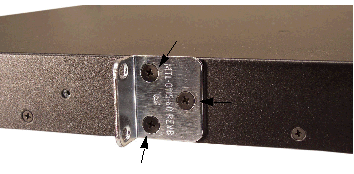
To remove center-mount equipment rack hardware:
- Remove the left rack ear by using a #1 Phillips-head screwdriver.
- Remove the right rack ear by unscrewing the three screws.
- Set the rack ears and screws aside.
Removing Hardware in Front-Mount Configurations
The chassis slides and rack ears must be removed before you can open the chassis.
To remove front-mount equipment rack hardware:- Remove the left chassis slide by using a #2 Phillips-head screwdriver.
- Remove the left rack ear by unscrewing the three screws.


- Remove the the two countersunk screws on the left rear side by using a #1 Phillips-head screwdriver.
- Repeat steps 1 - 3 on the right side of the Acme Packet 4600.
- Set the rack ears and screws aside
Opening the Chassis
Note:
Before opening the Acme Packet 4600, ground yourself using an ESD wrist strap or other comparable grounding system. Failure to do so could damage the Solid State Drive and the Acme Packet 4600.Note:
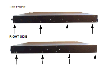
Use a #2 Phillips-head screwdriver for all chassis cover and side screws.- Unscrew the four countersunk screws on each side of the Acme Packet 4600 that
hold the chassis cover to the chassis.
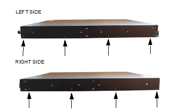
- Set these screws aside.
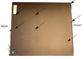
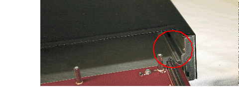
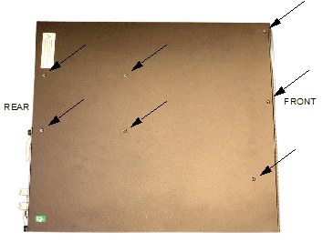
- Unscrew the seven countersunk screws on the top of the Acme Packet 4600 that hold the chassis cover to the chassis. The following is an image of the top of the chassis.
- Set the lid and screws aside.
- Lift the chassis lid off of the chassis and set aside.
Removing and Replacing the Solid State Drive
Note:
Before handling the Solid State Drive, ground yourself using an ESD wrist strap or other comparable grounding system. Failure to do so could damage the Solid State Drive or the Acme Packet 4600.Identifying the Solid State Drive
Once the Acme Packet 4600 is open, replacement is straightforward. The Solid State Drive (SSD) attaches electrically to the Acme Packet 4600 motherboard by a standard 2.5” SATA connector. In addition, it is secured to the motherboard by four screws.
The SSD is located at the front of the motherboard, on the left side as you view it
from the rear of the chassis. The SSD has brackets on each side, with four screws
attaching it to the motherboard.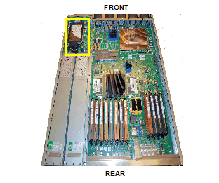
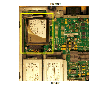
- Identify the four screws that attach the SSD to the motherboard.
- Identify the SATA connector attached to the SSD.
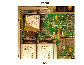
- Using a number 1 Phillips screwdriver, unscrew the four screws attaching the SSD to the motherboard.
- Hold the SSD in one hand, and the SATA connector in the other, and gently
disconnect the two. Note that the SATA cable should remain attached to the
motherboard.
Replacing the Solid State Drive
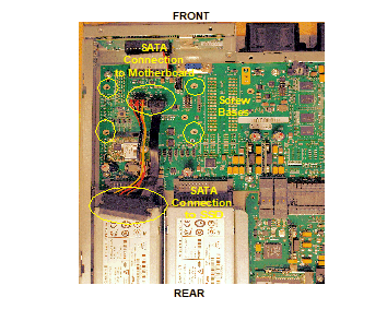
- Exchange the current SSD for the replacement, then re-attach the SSD to the SATA cable. The connector is keyed, so make sure the gap in the connector is lined up with the key in the SSD.
- Push down on the part of the SATA connecter attached to the motherboard to check to make sure the SATA cable is seated properly to the motherboard.
- Line up the screw mounts on the SSD with the screw bases, and tighten the screws. Be careful not to over-tighten the screws.
Postinstallation
After the Solid State Drive has been installed in the Acme Packet 4600, you can close the chassis and reinstall it in the equipment rack.
Attaching the Lid
- Set the lid on top of the Acme Packet 4600 chassis. The stickers are positioned at the chassis rear.
- Screw the eight countersunk screws into the top of the Acme Packet 4600 to
secure the chassis cover to the chassis. The following is an image of the top of
the chassis without any screws.
- Continue securing the chassis lid with four screws on each side.
Installing the Chassis in the Rack
Perform the reverse of the operations in the Physical System Removal section of this document.
Please refer to earlier sections of this document for full rack installation procedures.
Validating the SSD
Password: ******


-> dc
/boot/  - Volume is OK
243 MB

/code/  - Volume is OK
245 MB
/sata/  - Drive Present
476940 MB

Starting Diagnostic Executive...
Comm Express MCH 945 Present.
AHCI Support is Enabled.

Acme Packet Net-Net 4600
Diagnostic Executive Version 1.10
Creation date: Nov 25 2014 11:08:02
Board Level Diagnostics
Date & Time: TUE NOV 25 14:56:01 2014


[diag_proc] ->
Fan and Air Filter Maintenance
This section explains how to remove a fan and replace the air filter on your Acme Packet 4600.
Removing and Replacing Individual Fans
The individual fan is a user-serviceable, hot-swappable component. There are five individual fans in the Acme Packet 4600. If the Acme Packet 4600 experiences a fan malfunction, you must remove the existing fan and replace it with a functional one.
The hot-swappable fan removal and replacement procedures require that you have a replacement fan on hand. In order to maintain system operations, you must be able to remove the malfunctioning fan and quickly replace it with a functioning one to prevent the system from overheating.
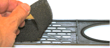
The Acme Packet 4600 air filter is located behind the front bezel and is a Field Replaceable Unit (FRU).
Note:
An over temperature condition can stop packet processing.If you do not have a replacement fan nearby, always shut down the system and disconnect the power before removing the malfunctioning fan to replace at a later time.
When removing and replacing a fan, remember to first ground yourself using appropriate ESD grounding equipment such as a wrist or heel strap.
To remove a fan:- Press two fingers against the left end of the plastic fan bezel and pull it
directly toward you. The fan bezel comes off the chassis. Set the fan bezel
aside. The individual fans are now exposed.

- Using a small bladed screwdriver, unscrew the two captive screws at each upper
left and lower right corners of the individual fan you are replacing.

- Pull the individual fan you just unscrewed directly toward you, out of the
chassis. Move the fan to an ESD-safe location.

Install Individual Fans
To obtain a replacement fan, contact customer support.
Replacing the fan is the reverse process as removing it.
To install a fan:Note:
The power connector should be on the lower side of the module when inserted into the Acme Packet 4600 chassis.- Carefully align the pins on the back of the fan with the holes in the chassis
midplane and install the fan into the slot.


- Using a small bladed screwdriver, tighten the two captive screws to hold the
fan into place.

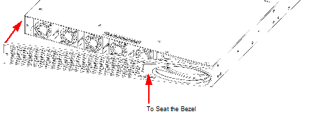
- Install the front bezel onto the Acme Packet 4600 by hooking the right side of
the bezel onto the chassis and then pivoting the bezel to the left until the
magnet catches the chassis. You may need to push on the left side of the display
opening to fully seat the bezel.

- The replacement fan and Bezel are installed onto the Acme Packet 4600.
Maintaining the Cooling Components
- Replace the fan filter every three months
- Clean the air inlets once a week.
Cooling maintenance encompasses cleaning the fan module and cleaning the air inlets on the front of the Acme Packet 4600 chassis. Cleaning the fan module requires that you remove the module itself. If you are not shutting down the Acme Packet 4600, this procedure must be performed quickly or else the system may overheat and cause packet processing to stop.
This maintenance should be performed alongside other preventive maintenance to take place within a planned maintenance or downtime window, during off-peak hours.
Optical Transceiver Removal and Replacement
- Converts electrical signals into optical signals used to communicate with other optical networking equipment.
- Serves as the receptacle for the LC duplex fiber optic connectors.
Optical transceivers are hot swappable and may be replaced while the Acme Packet 4600 is powered on. Leave the NIU installed in the Acme Packet 4600 as you extract the optical transceiver.
To obtain a replacement optical transceiver, contact customer support.
Note:
To prevent damage to the optical lens, Acme Packet recommends that the protective dust cover stay on the optical transceiver port when the physical interface card is not cabled.Removing an Optical Transceiver
- Unplug all fiber optic cables from the optical transceiver to be replaced.

- Pull the bale clasp latch out and down. It will pivot downwards on its hinge.
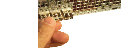
- Holding the extended bale clasp latch, pull the optical transceiver fully out
of its socket of the physical interface card.

Install an Optical Transceiver
- Slide the replacement optical transceiver into the socket on the NIU.

- Press on the face of the optical transceiver to seat it in the socket.

- Flip the bale clasp latch back into the rest position.

- Reconnect the optical cables to their corresponding ports.

Alarms
- Hardware and environmental
- Media link
Each alarm is assigned a severity level, depending on the details of the fault.
| Alarm Severity | Description |
|---|---|
| Minor | Functionality is impaired to a small degree (e.g., a single fan has failed) |
| Major | Pending failures or unexpected events are imminent (e.g., an LOS) |
| Critical | Catastrophic condition has occurred (e.g., the system is overheating) |
- Hardware temperature
- Fan speed
- Environmental sensor
- Power supply
- Voltage
- Physical interface cards
Important:
If different sensors report two or more events of the same severity with the same Alarm ID, only the first alarm gets reported.Hardware and Environmental Alarms
This section provides details about hardware and environmental alarms.
Hardware Temperature Alarm
The following table lists the hardware temperature alarm.
| Alarm Name | Alarm ID | Alarm Severity | Causes | Example Log Message | Graphic Display Window Message |
|---|---|---|---|---|---|
| TEMPERATURE HIGH | 65538 |
CRITICAL: >105°C MAJOR: >100°C MINOR: >95°C |
Fans are obstructed or stopped. The room is abnormally hot. |
Temperature: XX.XXC (where XX.XX is the temperature in degrees) |
Temperature X C (where X is the temperature in degrees) |
| If this alarm occurs, the Acme Packet 4600 turns the fan speed up to the fastest possible speed. | |||||
Fan Speed Alarms
The following table lists the fan speed alarm.
| Alarm Name | Alarm ID | Alarm Severity | Causes | Example Log Message | Graphic Display Window Message |
|---|---|---|---|---|---|
| FAN STOPPED | 65537 |
CRITICAL: any fan speed is <50%. Or speed of two or more fans is >50% and <75%.
MAJOR: speed of two or more fans is > 75% and < 90%. Or speed of one fan is >50% and <75% and the other two fans are at normal speed.
MINOR: speed of one fan> 75% and <90%, the other two fans are at normal speed |
Fan failure. |
Fan speed: XXXX XXXX XXXX where xxxx xxxx xxxx is the revolutions per minute (RPM) of each fan on the fan module |
Fan stopped |
| If this alarm occurs, the Acme Packet 4600 turns the fan speed up to the fastest possible speed. | |||||
Environmental Sensor Alarm
The following table lists the environmental sensor alarm.
| Alarm Name | Alarm ID | Alarm Severity | Cause(s) | Example Log Message | Graphic Display Window Message |
|---|---|---|---|---|---|
| ENVIRONMENTAL SENSOR FAILURE | 65539 | CRITICAL | The environmental sensor component cannot detect fan speed and temperature. | Hardware monitor failure! Unable to monitor fan speed and temperature! | HW Monitor Fail |
Power Supply Alarms
The following table lists the power supply alarms.
| Alarm | Alarm ID | Alarm Severity | Causes | Log Message | Graphic Display Window Message |
|---|---|---|---|---|---|
| PLD POWER A FAILURE | 65540 | MINOR | Power supply A has failed. | Back Power Supply A has failed! | X HW ALARMS: (where X is the number of hardware alarms |
| PLD POWER A UP | 65541 | MINOR | Power supply A is now present and functioning. | Back Power Supply A is present! | X HW ALARMS: (where X is the number of hardware alarms |
| PLD POWER B FAILURE | 65542 | MINOR | Power supply B has failed. | Back Power Supply B has failed! | X HW ALARMS: (where X is the number of hardware alarms |
| PLD POWER B UP | 65543 | MINOR | Power supply B is now present and functioning. | Back Power Supply B is present! | X HW ALARMS: (where X is the number of hardware alarms |
Voltage Alarms
The following table lists the voltage alarms.
| Alarm | Alarm ID | Alarm Severity | Cause(s) | Log Message | Graphic Display Window Message |
|---|---|---|---|---|---|
| PLD VOLTAGE ALARM 2P5V (2.5 Volt Rail) | 65544 |
MINOR EMERGENCY |
A PLD exceeds a predetermined threshold |
Voltage 2.5V CPU has minor alarm Voltage 2.5V CPU has emergency alarm, the system should shut down |
X HW ALARMS: (where X is the number of hardware alarms |
|
PLD VOLTAGE ALARM 3P3V (3.3 Volt Rail) |
65545 |
MINOR EMERGENCY |
A PLD exceeds a predetermined threshold |
Voltage 3.3V has minor alarm Voltage 3.3V has emergency alarm, the system should shut down |
X HW ALARMS: (where X is the number of hardware alarms |
|
PLD VOLTAGE ALARM 5V (5 Volt Rail) |
65546 |
MINOR EMERGENCY |
A PLD exceeds a predetermined threshold |
Voltage 5V has minor alarm Voltage 5V has emergency alarm, the system should shut down |
X HW ALARMS: (where X is the number of hardware alarms |
|
PLD VOLTAGE ALARM CPU (Host Voltage) |
65547 |
MINOR EMERGENCY |
A PLD exceeds a predetermined threshold |
Voltage CPU has minor alarm Voltage CPU has emergency alarm, the system should shut down |
X HW ALARMS: (where X is the number of hardware alarms |
NIU Alarms
The following table lists the NIU alarms. PHY0 and PHY1 are both located on the same NIU. PHY0 encompasses S0P0 and S0P1, while PHY1 encompasses S1P0 and S1P1. Therefore, both insertion and both removal alarms will be activated at the same time when the NIU is inserted or removed from the Acme Packet 4600.
| Alarm | Alarm ID | Alarm Severity | Cause(s) | Log Message |
|---|---|---|---|---|
| PHY0 Removed | 65550 | MAJOR | NIU S0Px was removed | Physical interface card 0 has been removed |
| PHY0 Inserted | 65552 | MAJOR | NIU S0Px was inserted | None |
| PHY1 Removed | 65553 | MAJOR | NIU S1Px was removed | Physical interface card 1 has been removed |
| PHY1 Inserted | 65554 | MAJOR | NIU S1Px was inserted | None |
Link and SDP Alarms
Link alarms are generated when a network cable is plugged into or unplugged from a configured network interface. For each possible network interface, an alarm exists that indicates whether the link goes up or down.
The following tables list detailed information about the Acme Packet 4600 NIU link alarms, including their ID assignments, severities, causes, log messages, and messages printed in the graphic display window.
Media Ethernet Link Alarms
The following table lists the NIU GbE and 10GbE interface link up/link down alarms.
| Alarm Name | Alarm ID | Alarm Severity | Cause(s) | Example Log Message | Graphic Display Message |
|---|---|---|---|---|---|
| LINK UP ALARM GIGPORT | 131073 | MAJOR | 1GbE S0P0 link up | Slot 0 port 0 UP | X LINK ALARMS (where X is number of alarming links) |
| LINK DOWN ALARM GIGPORT | 131074 | MINOR | 1GbE S0P0 link down | Slot 0 port 0 DOWN | X LINK ALARMS |
| LINK UP ALARM GIGPORT | 131075 | MAJOR | 1GbE S0P1 link up | Slot 0 port 1 UP | X LINK ALARMS |
| LINK DOWN ALARM GIGPORT | 131076 | MINOR | 1GbE S0P1 link down | Slot 0 port 1 DOWN | X LINK ALARMS |
| LINK UP ALARM GIGPORT | 131077 | MINOR | 1GbE S0P2 link up | Slot 0 port 2 UP | X LINK ALARMS |
| LINK DOWN ALARM GIGPORT | 131078 | MINOR | 1GbE S0P2 link down | Slot 0 port 2 DOWN | X LINK ALARMS |
| LINK UP ALARM GIGPORT | 131079 | MINOR | 1GbE S0P3 link up | Slot 0 port 3 UP | X LINK ALARMS |
| LINK DOWN ALARM GIGPORT | 131080 | MINOR | 1GbE S0P3 link down | Slot 0 port 3 DOWN | X LINK ALARMS |
| LINK UP ALARM GIGPORT | 131081 | MINOR | 10GbE S0P4 link up | Slot 0 port 4 UP | X LINK ALARMS |
| LINK DOWN ALARM GIGPORT | 131082 | MINOR | 10GbE S0P4 link down | Slot 0 port 4 DOWN | X LINK ALARMS |
| LINK UP ALARM GIGPORT | 131083 | MINOR | 10GbE S0P5 link up | Slot 0 port 5 UP | X LINK ALARMS |
| LINK DOWN ALARM GIGPORT | 131084 | MAJOR | 10GbE S0P5 link down | Slot 0 port 5 DOWN | X LINK ALARMS |
Management Ethernet Link Alarms
The following table lists the NIU management Ethernet port alarms.
| Alarm Name | Alarm ID | Alarm Severity | Cause(s) | Example Log Message | Graphic Display Message |
|---|---|---|---|---|---|
| LINK UP ALARM VXINTF | 131077 | MINOR | Mgmt0 link up | Port 0 UP | X LINK ALARMS |
| LINK UP ALARM VXINTF | 131078 | MINOR | Mgmt1 link up | Port 1 UP | X LINK ALARMS |
| LINK UP ALARM VXINTF | 131079 | MINOR | Mgmt2 link up | Port 2 UP | X LINK ALARMS |
| LINK DOWN ALARM VXINTF | 131080 | MAJOR | Mgmt0 link down | Port 0 DOWN | X LINK ALARMS |
| LINK DOWN ALARM VXINTF | 131081 | MAJOR | Mgmt1 link down | Port 1 DOWN | X LINK ALARMS |
| LINK DOWN ALARM VXINTF | 131082 | MAJOR | Mgmt2 link down | Port 2 DOWN | X LINK ALARMS |
SFP Presence Alarms
The following table lists the alarms that reflect when an SFP module is inserted or removed from an NIU.
| Alarm Name | Alarm ID | Alarm Severity | Cause(s) | Example Log Message | Graphic Display Message |
|---|---|---|---|---|---|
| SFP REMOVED GIGPORT 0 | 65568 | CRITICAL | S0P0 SFP Removed | Slot 0 Port 0 SFP Removed | X HW ALARMS: (where X is the number of hardware alarms |
| SFP INSERTED GIGPORT 0 | 65569 | CRITICAL | S0P0 SFP Inserted | Slot 0 Port 0 SFP Inserted | X HW ALARMS: (where X is the number of hardware alarms |
| SFP REMOVED GIGPORT 1 | 65570 | CRITICAL | S0P1 SFP Removed | Slot 0 Port 1 SFP Removed | X HW ALARMS: (where X is the number of hardware alarms |
| SFP INSERTED GIGPORT 1 | 65571 | CRITICAL | S0P1 SFP Inserted | Slot 0 Port 1 SFP Inserted | X HW ALARMS: (where X is the number of hardware alarms |
| SFP REMOVED GIGPORT 2 | 65572 | CRITICAL | S0P2 SFP Removed | Slot 0 Port 2 SFP Removed | X HW ALARMS: (where X is the number of hardware alarms |
| SFP INSERTED GIGPORT 2 | 65573 | CRITICAL | S0P2 SFP Inserted | Slot 0 Port 2 SFP Inserted | X HW ALARMS: (where X is the number of hardware alarms |
| SFP REMOVED GIGPORT 3 | 65574 | CRITICAL | S0P3 SFP Removed | Slot 0 Port 3 SFP Removed | X HW ALARMS: (where X is the number of hardware alarms |
| SFP INSERTED GIGPORT 3 | 65575 | CRITICAL | S0P3 SFP Inserted | Slot 0 Port 3 SFP Inserted | X HW ALARMS: (where X is the number of hardware alarms |
| SFP REMOVED 10GIGPORT 4 | 65576 | CRITICAL | S0P4 SFP Removed | Slot 0 Port 4 SFP Removed | X HW ALARMS: (where X is the number of hardware alarms |
| SFP INSERTED 10GIGPORT 4 | 65577 | CRITICAL | S0P4 SFP Inserted | Slot 0 Port 4 SFP Inserted | X HW ALARMS: (where X is the number of hardware alarms |
| SFP REMOVED 10GIGPORT 5 | 65578 | CRITICAL | S0P5 SFP Removed | Slot 0 Port 5 SFP Removed | X HW ALARMS: (where X is the number of hardware alarms |
| SFP INSERTED 10GIGPORT 5 | 65579 | CRITICAL | S0P5 SFP Inserted | Slot 0 Port 5 SFP Inserted | X HW ALARMS: (where X is the number of hardware alarms |
When an SFP module is inserted or removed from an NIU, there is no impact on system health.
