Illustrated Parts Breakdown
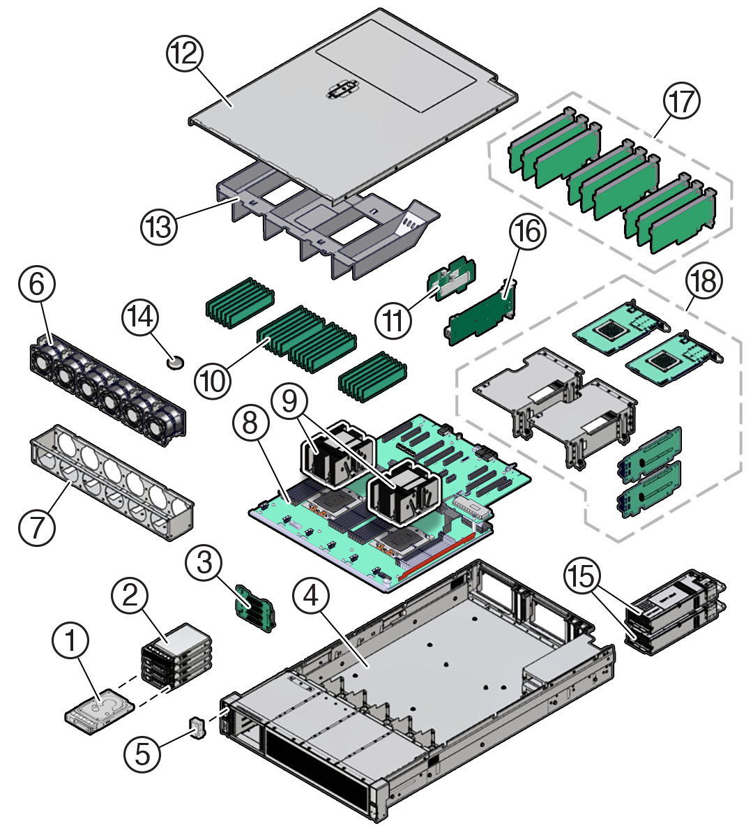
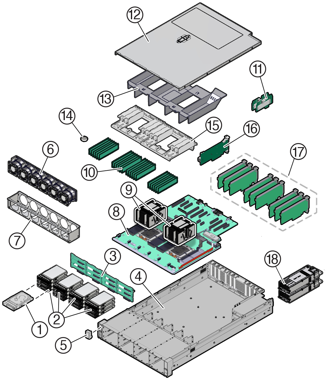
Identify major components of Exadata Server X10M with 4-Drive backplane and Exadata Server X10M with 12-Drive backplane.
Exadata Server X10M with 4-Drive backplane
The following figure identifies Exadata Server X10M major components with 4-Drive backplane.

| Callout | Description |
|---|---|
|
1 |
Storage drives, up to four 2.5-inch hot-pluggable PCIe-based NVMe SFF SSDs in 4-Drive backplane |
|
2 |
Storage drive bay cage |
|
3 |
4-Drive backplane (DBP) |
|
4 |
System chassis |
|
5 |
Front LED indicator module (FIM) |
|
6 |
Six fan modules (FM0-5) |
|
7 |
Fan tray |
|
8 |
Motherboard assembly (MB) |
|
9 |
Processors (P0, P1) and heatsinks (Single-processor systems contain only a single processor in socket P0; socket P1 contains a cap to protect processor socket pins.) |
|
10 |
24 DIMMs (Twelve DIMMs are supported in single-processor systems and the DIMMs must be installed in P0 DIMM sockets.) |
|
11 |
Internal M.2 SSD memory with two internal M.2 Risers |
|
12 |
Top cover |
|
13 |
Air baffle |
|
14 |
System RTC battery |
|
15 |
Two power supplies (PS0, PS1) |
|
16 |
(Optional) Oracle RoT card |
|
17 |
(Optional) Nine HHHL PCIe cards PCIe slots 1 through 4 are nonfunctional in single-processor systems. |
Exadata Server X10M with 12-Drive backplane
The following figure identifies Exadata Server X10M major components with 12-Drive backplane.

| Callout | Description |
|---|---|
|
1 |
Storage drives, up to twelve 3.5-inch hot-pluggable SAS-3 LFF HDDs in 12-Drive backplane |
|
2 |
Four storage drive bay cages |
|
3 |
12-Drive backplane (DBP) |
|
4 |
System chassis |
|
5 |
Front LED indicator module and temperature sensor (FIM) |
|
6 |
Six fan modules (FM0-5) |
|
7 |
Fan tray |
|
8 |
Motherboard assembly (MB) |
|
9 |
Processors (P0, P1) and heatsinks (Single-processor systems contain only a single processor in socket P0; socket P1 contains a cover to protect processor socket pins.) |
|
10 |
24 DIMMs (Twelve DIMMs are supported in single-processor systems and the DIMMs must be installed in P0 DIMM sockets.) |
|
11 |
Internal M.2 SSD memory with two internal M.2 Risers |
|
12 |
Top cover |
|
13 |
Air baffle |
|
14 |
System RTC battery |
|
15 |
PCIe card shroud (9-slot PCIe card back panel) |
|
16 |
(Optional) Oracle RoT card |
|
17 |
Nine HHHL PCIe cards PCIe slots 1 through 4 are nonfunctional in single-processor systems. |
|
18 |
Two power supplies (PS0, PS1) |