| Skip Navigation Links | |
| Exit Print View | |

|
Sun Dual Port 10GBase-T ExpressModule User’s Guide |
Understanding the Installation Process
Installation Overview (Oracle Solaris 10)
Installation Overview (Oracle Solaris 11)
Installation Overview (Windows)
Power and Environmental Requirements
Verify the Driver Version (Oracle Solaris 10)
Verify the Driver Version (Oracle Solaris 11)
Remove the Driver (Oracle Solaris OS)
Download and Install the Driver (Linux)
Download and Install the Driver (Windows)
Verify the Installation (Oracle SPARC)
Verify the Installation (Oracle Solaris x86)
Verify the Installation (Linux)
Verify the Installation (Windows)
Create Driver Instance Files (Oracle Solaris 10)
Configure the Network Host Files (Oracle Solaris 10)
Boot Over a 10 GbE Network (Oracle Solaris x86 and Linux)
Install Oracle Solaris 10 Over a Network (Oracle SPARC)
Administering Driver Parameters and Jumbo Frames
Driver Parameters (Oracle Solaris OS)
Set Driver Parameters (Oracle Solaris OS)
Configuring Jumbo Frames (Oracle Solaris OS)
Change the MTU Temporarily (Oracle Solaris 10)
Change the MTU Temporarily (Oracle Solaris 11)
Configure Jumbo Frames (Linux)
Configure Link Aggregations (Oracle Solaris 10)
Display Information About Link Aggregations (Oracle Solaris 10)
Delete Link Aggregations (Oracle Solaris 10)
Configure Static VLANs (Oracle Solaris 10)
Analyze Why the Device Link Is Missing
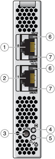
The front panel contains dual ports with two status LEDs assigned to each port. In addition, there is an Attention button (labeled ATTN) and two system-level LEDs located next to the ATTN button
Figure 2 Front Face of the EM

Figure Legend
1 Port 0
2 Port 1
3 ATTN (attention) button
4 OK LED
5 Attention (fault) LED
6 Speed LED
7 LNK/ACT (link/activity)
The following table explains the behavior of the speed and activity/link LEDs.
|
When you want to perform a hot-plug operation with an EM, press the ATTN button. This removes power from the slot so that the EM can be removed while the chassis remains powered up.
Note - Power remains present at the slot for a period of time after the ATTN button is pressed. This is referred to as the power transition period.
 | Caution - Do not insert or remove the EM during the power transition phase of a hot-plug operation. This power transition phase is the period just after the ATTN button is pressed when the EM may not be fully isolated from the power source. |
In addition to the port status LEDs, there are two LEDs next to the ATTN button. The following table explains their meaning.
|